Green Energy Options Solo III Assembly instructions

Installer guide
Solo III + hub version

2
Important safety notice
•This equipment contains two disconnection switches for interruption of supply that do not
provide supply isolation. Means of isolation from the supply must be provided as part of the
building installation. Do not work on the equipment unless the supply is isolated. If isolation is
made by removal of fuses or other cut-outs, the removed devices must be kept secure from
replacement whilst work is performed. If isolation is provided by a switch, the switch must
conform to the requirements of IEC 947-1 and IEC 947-3 or equivalent.
•Over-current protection is not provided by the equipment and must be provided as part of the
building installation. For the domestic supply the maximum over-current device rating is 100A
at 415V AC, conforming to the requirements of BS1361 or equivalent.
•Only suitable trained and qualied personnel shall be allowed to work on the equipment. Local
safety standards shall be observed and shall take precedence over these regulations in points
of conict.
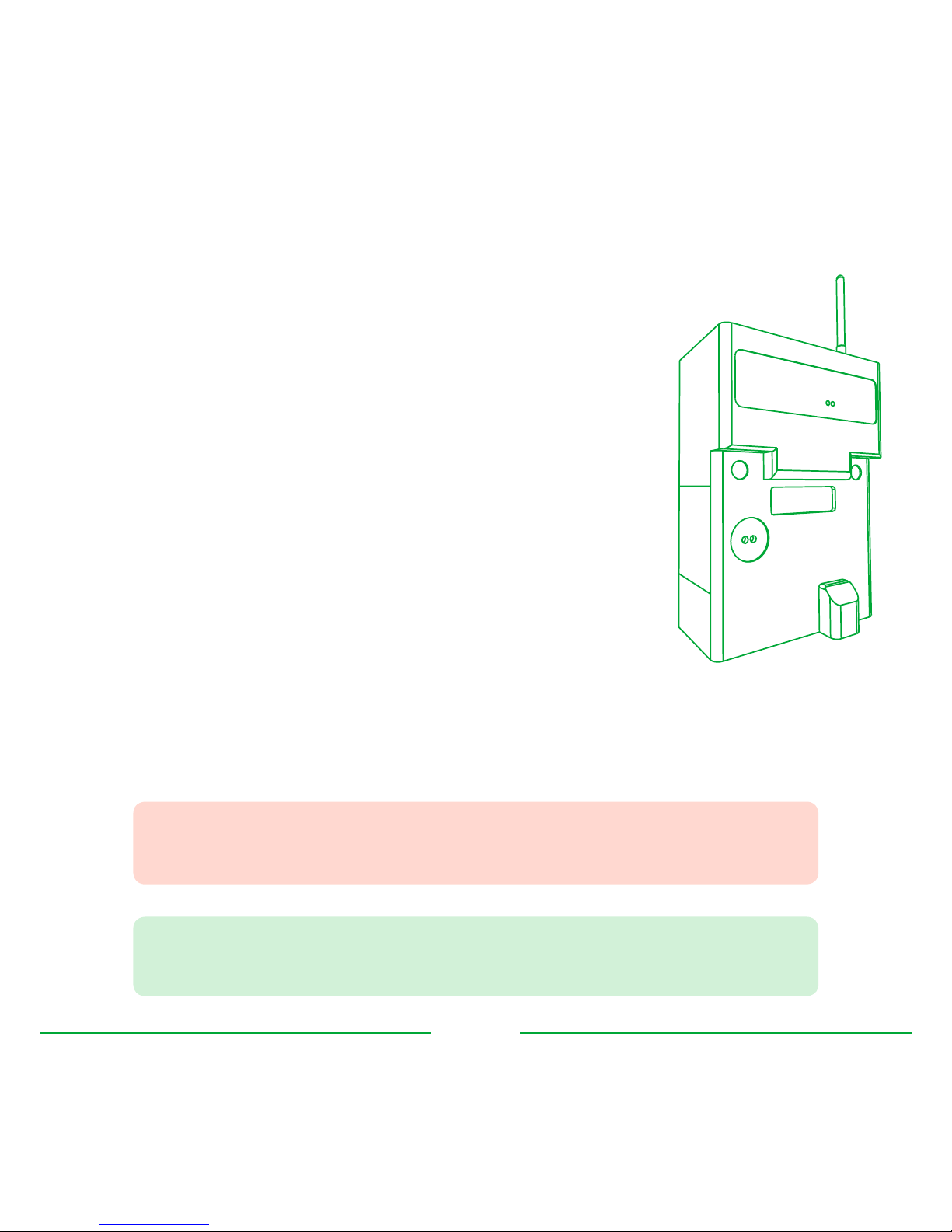
•The meters must be held securely during installation. They can cause injury if dropped.
•Meters that have fallen must not be installed. Even if no damage is apparent, meters must be
returned to the manufacturer for testing. Internal damage can result in functional disorders or
short-circuits.
•The meters must only be cleaned whilst disconnected and with a dry cloth without solvent and
on no account be cleaned with running water or with high-pressure devices. Penetrating water
can cause internal short-circuits.
•A terminal cover protects inadvertent exposure to the meter tail connections and must be
tted prior to energising the electrical supply.
jThe following safety regulations must be observed at all times.
Failure to observe precautions could result in severe injury or death.

3
System overview

4
Twin element meter
The twin element meter connects to both the PV system and the
consumer unit to allow the Solo III system to measure generation,
import, export and consumption via a low-powered radio link.
The meter measures active and reactive energy consumption in
single-phase two-wire installations.
The meter:
•is intended for installation in E2 electromagnetic and M1
mechanical environments where shock and vibrations are of
low signicance (2004/22/EC directive),
•is to be installed directly onto the distribution company’s
supply tails and generation cabling within a residential
environment,
•conforms to British Standards,
•must be installed away from sources of electromagnetic
interference,
•is classied as a Category III device according to EN61010-1 2010.
jMeters must be tted by qualied personnel and should be used in
accordance with the technical specications provided in this installer guide.
$A metal meter cabinet may aect communication between the meter
and the hub or (optional) display.

5
Solo III display (optional)
The optional Solo III display is paired to the hub to show the user
cost and energy consumption, import and export and generation
information in real-time. A limited amount of historical data is also
visible.
The display does not contain any user serviceable parts and
does not contain batteries. It is powered using an external power
supply which is supplied with the unit.
Hub
The hub connects the meter to the internet and allows the user to
view their generation, import, export and consumption data online
using an application on their smartphone, tablet or computer.
This requires a physical connection to an RJ45 point either on a
broadband router or other network switch.
The hub does not contain any user serviceable parts and does not
contain batteries. It is powered using an external power supply
which is supplied with the unit.
$It is recommended that the hub is installed rst to give it time to
perform an automatic software update whilst the meter is installed.

6
Meter installation

7
Preparation
Isolation of power supply
Before installation of the meter, you must do the following:
•Isolate the consumer and PV supplies
Mounting the meter
The meter must be securely mounted to a wall or meter board.
•Unscrew and remove the lower-front meter panel to expose
the terminal connections
•Mount the meter using a suitable round headed screw that is
tted to the wall or meter board. The width of the slot in the
hanging bracket is 5mm
•The screw depth should be adjusted so that the head ts
snugly under the hanging point and the meter is held rm
against the wall or board
•Finally the meter should be rmly screwed to the wall or
board using the two mounting holes located under the
terminal cover
jBefore installation of the meter the supplies to both the consumer
and PV systems must be isolated. Never operate on a live system
and power should only be restored once the meter installation is
complete.

8
Wiring
The meter should be installed and wired according to the diagram below. Neutral is only required
to be connected to either terminal 2 or 3 of the meter.
(A) All Nwires can
be connected
together
(B) Connect Nto
either terminal
2or 3
(C) Connect Lfrom
utility meter to
terminal 4
(D) Connect Lfrom
PV MCB / isolator
to terminal 5
(E) Connect Lfrom
consumer unit
to terminal 1
Twin-element meter
2134
5
Element A
Element B
Utility meter
LOUT
NOUT NIN
LIN
20A
isolator
16A MCB
Utility supply
PV inverter
100A
isolator
Consumer unit A
C
D
B
E
jYou must check all wiring before restoring power to the consumer
and PV systems and the new meter. The meter must only be used in
single-phase installations.

9
Post-install verication
Complete installation
Before restoring power, do the following:
•Double-check the wiring to the meter
•Re-insert the meter front panel and secure tightly
•Restore power to the consumer and PV systems
•Attach the small 868MHz radio antenna to the top of the meter module
Meter diagnostics
The LCD display on the meter will turn on - this conrms that power is OK.
Below is a typical screen:
Once the system has been powered on, the two LEDs on the module indicate the module is
correctly installed.
$The meter module is transmit only - the LEDs will ash irrespective of
whether it is paired to a Solo III display or hub.

10
Hub installation

11
Connections & buttons
The hub has two buttons with LEDs on the top and
three connections on the back:
(A) Link button (f) and status LED for wireless
pairing
(B) Cloud button (g) and status LED for the
cloud service connection
(C) Ethernet socket for connecting the hub to
the consumer’s broadband router or network
switch
(D) Power socket for mains power
(E) USB socket (reserved for future use)
Connecting to the network
The hub needs to be connected to an available
Ethernet socket on the consumer’s broadband
router. If no socket is available, then a suitable
network switch will be required.
•Connect one end of the supplied Ethernet
cable into the router / switch
•Connect the other end into the Ethernet
socket on the hub (C)
AB
C
A B
CD
E

12
Powering the hub
The hub is packaged with adapter pins for a number of countries - recycle adapters that are not
suitable for your country
•Assemble the power supply by twisting the
pins on to the adapter in a clockwise direction
until you hear a click
•Connect the power adapter into the hub (D)
•Insert the power supply into the electricity
socket
•Power on the hub
Firmware update
The hub comes pre-installed with rmware that will automatically update once connected to the
broadband network.
Once the update has completed, the status LEDs will indicate the state of the hub (as shown in the
status table).
jDuring update, the two status LEDs will ash green alternately
to indicate the update is in progress. The update will last for
approximately four minutes.
Do not switch o the power or disconnect the hub from the
broadband during this time.

13
Hub status LEDs
Hub ready for pairing
After the hub has updated and is ready to pair
with the meter, the status LEDs will show the
following:
•Link LED (f) is RED
•Cloud LED (g) is AMBER
Status LED meanings
The following table shows what the dierent coloured LEDs mean.
LED Colour Meaning
fOFF Check the power supply to the hub
RED The hub is not paired to the meter and / or Solo III display
AMBER (ashing) The hub is in pairing mode and waiting to pair with the meter or
Solo III display
AMBER Devices paired, but signal lost (see FAQs)
GREEN The hub is paired to the meter
gOFF Check the Ethernet cable - the hub is unable to obtain a network
IP address
AMBER (ashing) Requesting association with online service
AMBER The hub is connected to the broadband and ready to associate
with the user’s account
GREEN The hub is connected to the broadband and associated with the
user’s account

14
Pairing hub to meter
The hub will need to be paired to the meter by completing the following steps:
$If the link LED (f) is green before pairing, then the hub may have
previously been paired with another meter and it must be reset
before pairing to the new meter. See FAQs at the end of this guide.
Press and hold button on front of
meter for 5 seconds, then release
Press and hold link button (A) on the hub
until the status LED (f) flashes amber
within 5 minutes
Link status
LED (f) turned
green?
Hub is now paired
to meter
YESNO
wait
5 minutes

15
Solo III display

16
Display overview
The Solo III system can have an optional display connected to show real-time generation,
consumption and savings. The display is not needed for installations that only require online access
and can be added to the system in the future.
For more information on the Solo III display or to make a purchase, visit:
http://www.greenenergyoptions.co.uk/support/solo3
Powering the display
The Solo III display is packaged with adapter pins for a number of countries - recycle adapters that
are not suitable for your country. Do not power the display using the USB port (for future use).
•Assemble the power supply by twisting the
pins on to the adapter in a clockwise direction
until you hear a click
•Connect the power adapter into the Solo III
display
•Insert the power supply into the electricity
socket
•Power on the Solo III display
•Once the display is powered on, it will
show PAIR HUB on the screen
$If the display has previously been paired to a hub, it will need
to be reset. Refer to the back of this installer guide for details on
performing a factory reset.

17
Pairing to the hub
The display will need to be paired to the hub by completing the following steps:
Power on Solo III display
Press and hold link button (A) on the hub
until the status LED (f) flashes amber
within 5 minutes
PAIR HUB
on screen?
Perform factory
reset of display
NO
NO
Press left button ()
HUB OK
on screen?
Display is now
paired and ready
YES
YES

18
Using the display
The Solo III will immediately start to show live generation and consumption readings taken directly
from the smart meter.
Pressing the left button will cycle through the following
screens:
•GEN TODAY
Total generation from the PV system for today
•USE TODAY
Total usage for the whole house for today
•IMP TODAY
Total amount of energy imported from the grid for today
•EXP TODAY
Total amount of energy exported to the grid for today
Pressing the right button will change between TODAY, Y’DAY
(yesterday), THISWK (this week), LSTWK (last week) and this and
previous months (e.g. AUG, JUL).
Pressing the middle button will also show SAVE (for savings),
COST (for total cost) and EARN (for earnings from the PV
system).
$After a new installation all the readings will start from zero and start
to increment from the point at which the Solo III and hub are rst
paired.
When associated with energynote®, all data will be reset.
solo III

19
energynote®

20
Account activation
The Solo III system provides in-depth analysis on generation, consumption and other earnings
related information and can be accessed from a desktop, laptop or tablet computer or via a
smartphone.
Account creation
Log on to http://www.energynote.eu/ and follow the instructions to create an account.
•Log on to http://www.energynote.eu/
•Click Register now
•Enter the end-user’s name, valid email address and a password
•Click Register to create the account
Account verication
Within ve minutes the user will receive an email with instructions on how to complete their
account creation.
$Online activation of energynote® requires that the end-user is
available to create an online account using a valid email address.
It is strongly advisable to complete the account activation during the
system installation otherwise all data accumulated in the intervening
time between installation and association may be lost.
Other manuals for Solo III
1
Table of contents
Popular Measuring Instrument manuals by other brands

Schrack Technik
Schrack Technik KIZ product manual

Siemens
Siemens SITRANS FC720 operating instructions

Renesas
Renesas MCU Signal Measurement Board PCA7759 user manual

Endress+Hauser
Endress+Hauser Deltabar S PMD70 technical information

Renkforce
Renkforce 2617740 operating instructions

MetLogix
MetLogix M1 user guide