AEM 30-5501 User manual
30-5500
30-5501
30-5502
30-5503
AEM Performance Electronics
2205 126th Street Unit A, Hawthorne, CA 90250
Phone:(310) 484-2322 Fax:(310) 484-0152
http://www.aemelectronics.com
Instruction Part Number:10-5500
Document Build 11/17/2016
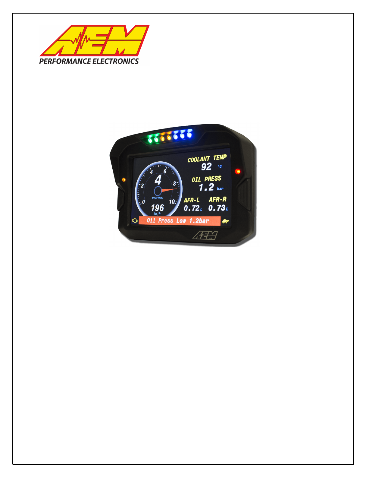
CD-7/CD-7L
COLOR DASH DISPLAY
CAN LOGGER SYSTEM

2
Part I - Quick Start Guide
The manual contains two parts. Part I is a quick start guide that includes basic information to get you up and
running quickly.

3
Introducing AEM DashDesign
The AEM Color Dash Display and CAN Logger includes the AEM CD-7 / CD-7L color display and AEM
DashDesign editing software. Screen pages are designed graphically. The screen layout displayed in AEM
DashDesign is identical to the layout displayed on the AEM CD-7 / CD-7L.
In addition to the graphical display editor, AEM DashDesign also provides a comprehensive setup editor to
program the input, output and mathematical functionality of the AEM CD-7 / CD-7L.
Once created, setups are uploaded to the AEM CD-7 / CD-7L via a USB link.
Kit Contents

4
CD-7 Features
·Full color CAN display and logger (CD-7L only)
·Completely user definable CAN receive
·Dual CAN bus
·Full graphics display with up to 6 different pages
·Unit ships with 6 display pages for the AEMNet data stream as the default setup
·Completely user definable graphical layouts
·Stand-alone PC program to create and customize layouts
·Water resistant enclosure with rear facing DTM 12 pin connector
·7" (diag) 800x400 super bright color display
·Night mode input
·7 shift lights and 2 alarm LEDs
·200mb onboard logging memory (CD-7L only)
·Up to 100hz sample rate (CD-7L only)
·Log data downloaded and viewed with AEMdata via USB port with sealed bulkhead extension cable (CD-7L
only)
·Beacon input
5
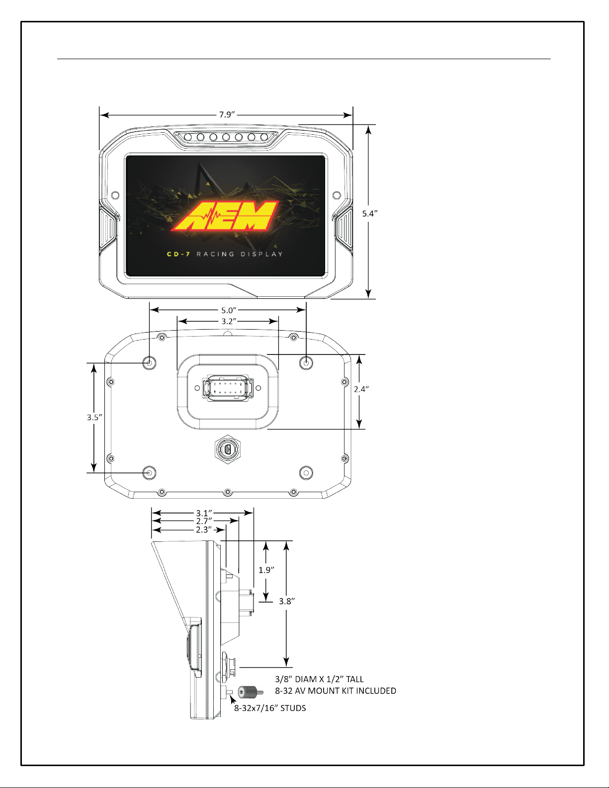
CD-7 Mechanical and Mounting
6
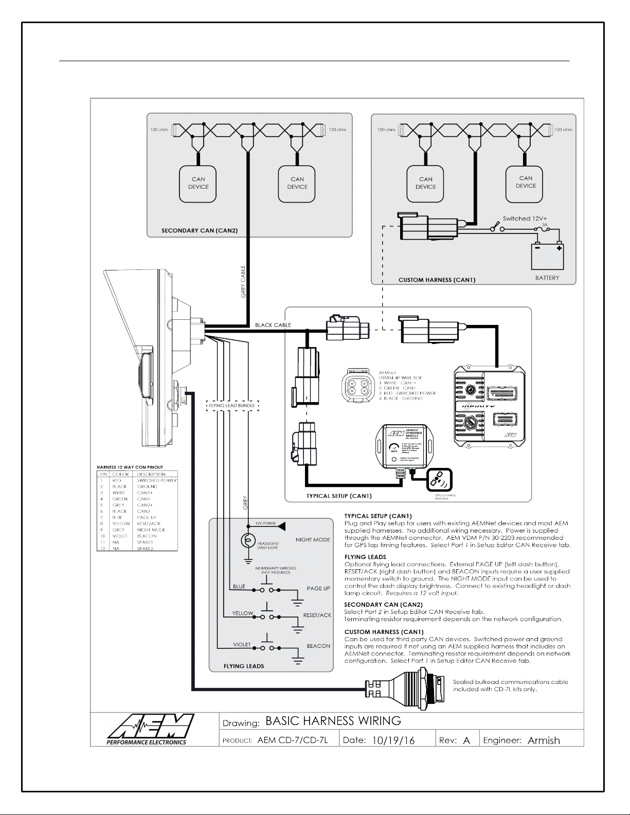
CD-7 Harness and Wiring

7
Installing AEM DashDesign
AEM DashDesign is distributed as a single install executable. To install, run AEM DashDesign Setup.exe and
follow the on-screen instructions.
Installing USB Drivers
The installation program will automatically install the USB drivers required by AEM CD-7 / CD-7L. However, on
rare occasions, it may be necessary to install the USB drivers manually. To do this:
·Connect the AEM CD-7 / CD-7L to the PC.
·When the add new hardware wizard appears, select "Install from a list or specific location" and click Next.
·Choose "Search for the best driver in these locations" and check "Include this location in the search"
·Click the Browse button and navigate to the Drivers folder sub folder in the AEM DashDesign installation
directory.
·Click the Next button and the driver installation will proceed automatically.
VDM for GPS speed and lap timing
The AEM Vehicle Dynamics Module, PN 30-2203 can be used in conjunction with the AEM CD-7L dash for lap
timing and track mapping features.
VDM Features:
·GPS latitude & longitude delivers AEMdata track map functionality via AEMnet CANbus
·Easily Add GPS, lateral G, altitude, pitch and roll data to engine data logs!
·Simply install it in the correct position, connect to AEMnet and the data streams through AEMnet CANbus!

8
·Continuous time data can be used for Infinity USB log file naming
·Accelerometers supply all 3-axis acceleration data for chassis tuning
·Ideal for road racers who want to use the gyrometer data for suspension adjustments
·Perfect for drag racers who want G-loads and wheel stand data
·GPS vehicle speed, heading and altitude logged for data analysis, lap comparisons
·Status LED indicates power & GPS signal
·Weather resistant enclosure with IP67 rated GPS/GLONASS antenna
Go to Setup | Lap Timing... Select the GPS button to configure for GPS lap timing. A virtual start/finish line
creation feature allows you to use the beacon input (violet wire in flying lead harness) to set a virtual start/finish
line. While driving the course, press the momentary beacon switch when you cross the start/finish line. Hold
for a few seconds until the left and right LEDs flash. The system captures the location information when you
first press the button. Holding for a few seconds eliminates the likelihood of false triggering the input. You can
define your virtual track width in the dialog window. Set to the approximate width of the track surface plus
some extra. The dash creates a start finish line the width of the Track Width/m setting perpendicular to the
heading when the start finish is set. It then checks whether the previous two points cross this line; the only
caveat being that the heading is +/- 90 degrees of the original heading.

9
Installation
The VDM is equipped with an AEMnet connector (power, ground, and CAN)
so that it is a true plug and play experience when used with other AEMnet
products such as the Infinity ECU.
Ideally, the VDM module should be installed near the center (both fore/aft
and side-to-side) of the vehicle and as low as possible. For example, the
module may be mounted to the floor of the vehicle between the two front
seats. The module should be mounted using the provided "hook-and-loop"
material or may be more rigidly mounted using fasteners through the
module's mounting ears. Take care to avoid over-torquing mounting
fasteners, if used.
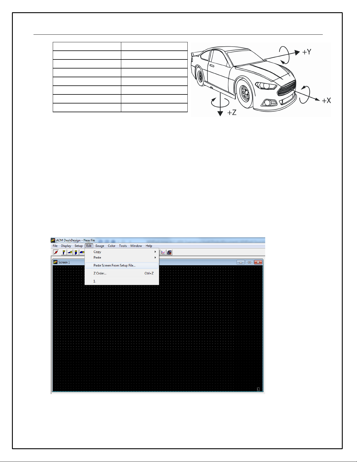
The external markings on the module indicate the orientation of the
accelerometer and gyro axes. Typically, the module is mounted so that
"+x Accel" is pointed towards the front of the vehicle in the direction of
travel. Please make note of this orientation for use when analyzing the
data later on.
The antenna should be mounted in a location where the top is pointed
towards, and has a clear view of, the sky. The bottom of the antenna is
magnetic or additional hook-and-loop material is provided for mounting; the
dashboard or rear package shelf are not acceptable locations. The
antenna should be mounted as high as possible in the center of a metal
roof away from other antennas or structures. If the roof of the vehicle is
non-metallic then a flat piece of metal at least five inches in diameter, to
function as a ground plane, should be fabricated upon which the antenna
should be placed.
10
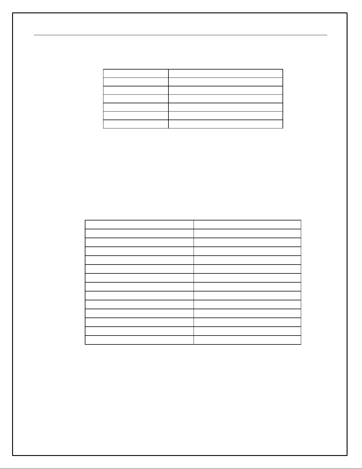
Status LED
There is a status LED located on the top of the VDM module that gives an indication of its operating status,
specifically the quality of the current GPS signal:
LED
Description
OFF
The device is not powered
FLASHING RED
No valid GPS fix
RED
Valid fix, zero satellites in view
FLASHING GREEN
Less than 4 satellites in view
GREEN
4 or greater satellites in view
OTHER
Please contact AEM Support
Channels / Data
GPS
The VDM utilizes an internal 5Hz GPS/GLONASS receiver with a matching external active antenna. Faster
time to fix, and better global coverage is afforded by the support of both the GPS and GLONASS
constellations. The module is designed with an internal super capacitor that will retain the last known satellite
position (ephemeris) while power is disconnected from the VDM for up to 2.5 hours. This will allow for a very
fast time to fix (<1 sec typ) once the device is turned on again; if power is removed for greater than the 2.5
hours then the time to fix will increase. The capacitor is automatically recharged and never needs to be
replaced such as is the case with a more traditional battery.
The following GPS channels are output on AEMnet for logging on your Infinity ECU or other device:
Channel Name
Notes
GPS Latitude [deg]
+ = North, - = South
GPS Longitude [deg]
+ = East, - = West
GPS Speed [mph]
Speed
GPS Altitude [ft]
Above Mean Sea Level (MSL)
GPS Course [deg]
Course over ground, NOT heading
GPS Satellite Count
"Visible" number of satellites
GPS Valid
1 = Valid Fix, 0 = No Fix
GPS Year
UTC Time
GPS Month
UTC Time
GPS Day
UTC Time
GPS Hours
UTC Time
GPS Minutes
UTC Time
GPS Seconds
UTC Time
Accelerometer / Gyroscope
The following accelerations and yaw rate channels are output on AEMnet for logging on your Infinity ECU or
other device:
11
Channel Name
Notes
Acceleration X[g]
*Longitudinal
Acceleration Y [g]
*Lateral
Acceleration Z [g]
*Vertical
YawRate X[deg/s]
*Roll
YawRate Y [deg/s]
*Pitch
YawRate Z [deg/s]
*Yaw
*If +x is mounted in the direction of travel
Display Setups
The display setup file has the extension .aemcd7 and contains all the information needed to configure a color
display including connection definition, sensor calibration and screen layout.
Default Display Setups
AEM supplied setup files will be located in the \Documents\AEM\DashDesign\Setups folder.
You can copy entire pages from another file. First, make sure the target page is open and selected and that
the layout is unlocked.
Select: Edit | Paste Screen From Setup File
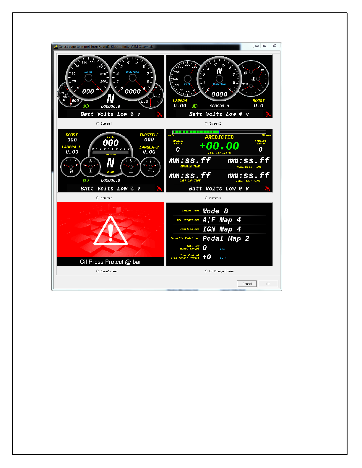
Select the file that contains the screen you want to copy. A window will open showing the six screens in the
target file.
12
Select the screen you want to import by clicking on the screen name and Clicking OK.
NOTE: Any missing bitmaps and bitmap selectors will be imported with the page. Bitmaps of the same name
are not replaced which potentially could cause unexpected results if bitmaps had been changed between
setups. Channel names carry over so even if you import a .dbc file after copying the screens, the names will
be tallied up (if they are the same). Any variable string gauges will show "No Input" if the output name is not
present. Editing any gauge where the output name is not present will show a blank in the output name - the
name is still there and will be used if the output is created at a later date though if you change the combo, it
will change the output as expected.
Opening and Saving Setups
To Open an existing color display setup:
·Select File | Open.... The file open dialog is shown.
·Select the required display setup file and click Open.
The last five files opened can be accessed by selecting File | Reopen followed by the appropriate file from the
sub menu.

13
To save a setup under a new filename, select File | Save As...., enter a file name in the file save dialog and
click the Save button. To save a setup with the current name, select File | Save.
If a setup or AEM DashDesign is closed and the setup has changed since the last save, a prompt will appear
asking if the changes to the setup are to be saved. Select Yes to save the changes, No to abandon the
changes or Cancel to return to editing the current setup.
Basic Editing of Default Setups
To view screens for editing go to Display | Screen X
14
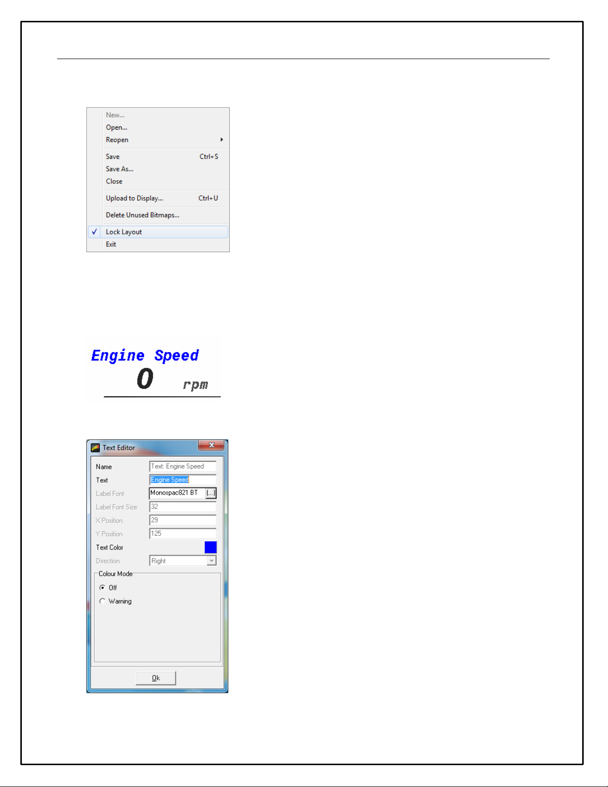
The Layout Locked feature displayed at the bottom right of the screen prevents unwanted moving of screen
items.
The Layout Locked feature can be disabled by going to File | Lock Layout or by clicking the red Layout
Locked area of the screen. Caution as inadvertent clicks and drags can move items unintentionally. Some
basic editing of the default screens is possible even with the Layout Locked feature turned on. It is a good idea
to leave the Layout Locked activated until you specifically need to move or delete a gauge. Having it on
prevents you from accidentally moving a gauge or deleting one inadvertently.
Double clicking on the Engine Speed text label in the example above will display the available editing menu.
The dialog allows editing of all unlocked characteristics if Layout Locked is turned on. Locked characteristics
are typically related to size and position. To change the text displayed in the text label example above, simply

15
highlight the text and edit. Double clicking on the "0" in the example above opens the value label editor. This
is live data displayed on the screen.
Here you can change the input displayed at this location. Click on the drop down to view a list of available
channels.
The Display Editor
The display editor is the core tool for editing a setup. To open the tool, go to Setup | Display...

16
You can think of the display editor as a collection of tools for creating items on your screens. A AEM
DashDesign setup consists of four logical components: Sources, outputs, sensors and gauges. These are
defined as follows:
·Sources or primary inputs are raw data manipulated by an operation.
·Outputs are objects that obtain information from one or more sources or other outputs. An output
manipulates the obtained data according to the operation associated with the output. The result can then
be used in a gauge or another output.
·Operations are objects that define how the data is manipulated by an output. Examples of operations are
scalars, functions and alarms.
·Gauges are objects that are placed on a screen page. There are two types of gauge; static and variable.
·Static gauges do not change their appearance on the screen and include gauges such as text labels
or bitmaps.
·Variable gauges change their appearance to reflect data obtained from an output. Examples of
variable gauges are bar graphs, tachos and numerical text gauges.
·Predefined Outputs are pre-configured within the system and can be used in many ways. Some
examples include: Log Mem Free (kb) which displays the amount of free logging memory (CD-7L only) and
Night Mode Input Status. This output displays the state of the Night Mode 12vinput (Grey wire in flying
lead bundle). Click the Show Predefined Outputs box in the Display Editor to
add all Predefined Outputs to the list.

17
Default CAN .dbc Support
The AEM DashDesign includes a CAN .dbc import feature. A .dbc file is a standardized format for defining a
set of CAN messages. Click on the CAN Receive tab in the Setup Editor.
Click on the Import DBC... button to load or append a new .dbc file.
18
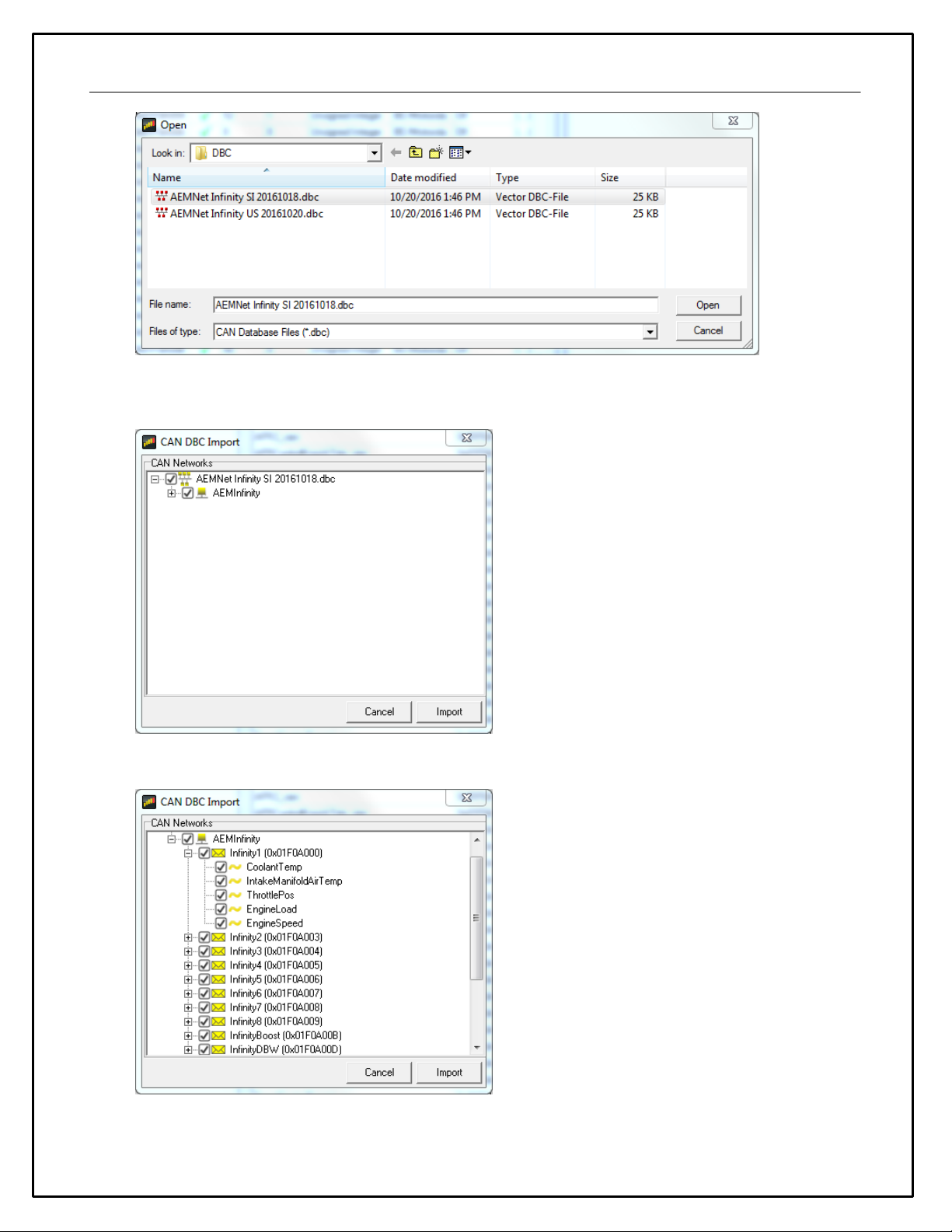
Available .dbc files will be located in the \Documents\AEM\DashDesign\DBC folder. Selecting a file will open
the import dialog.
The levels can be expanded by clicking on the plus symbol.

19
Select the channels for import by clicking the boxes. All available channels are selected by default. Click the
Import button to import. All CAN message information is automatically imported along with necessary Scalar
and Bit string operations. The channels are now available for assignment.
Logging (CD-7L only)
AEM CD-7 / CD-7L has 200Mbytes of internal data logging memory and supports logging rates of up to 100Hz.
Data is downloaded and analyzed with AEMData Analysis software.
To configure logging, select Setup | Logging to show the log setup window. Channels available to be logged
are shown on the left hand side. To log a channel, select the desired rate from the Log Rate column. Logging a
specific channel also automatically selects all other children and parent channels for logging at the same rate.
AEM CD-7 / CD-7L inserts markers in the data to indicate various states and these are displayed in AEMData.
The following markers may be inserted by AEM CD-7 / CD-7L:
·Lap - This is inserted when the beacon input is triggered and is typically used for lap timing.
·Power - This is inserted when the display is configured to start logging immediately on power up.
·Log Start - This is inserted when the log start condition is met after power up
·Overrun - The display has been unable to write the log data to the memory in the time available. Either
reduce the number of logged channels or reduce the complexity of the display screen.
The logging can be started or stopped dependent on channel conditions. Every time a new log is started, a
new Log Run is created in the logger. Log runs can be downloaded individually with GEMS Data Analysis
which reduces the time taken to download the data.
The log can be started in one of three ways:
·Single input start/stop - When the specified input is non zero, the log will be started. When zero, the
log will be stopped. For example, if the channel EngineSpeed is used as the trigger, the logger will log
anytime the engine is running.
·Twin start/stop triggers - When the Start trigger is non zero, the log will be started. When the Stop
trigger is non zero, the log will be stopped.
·Log Always - The logging starts logging immediately on power on and will log until switched off or until
the log is full.
20
Enabling logger adds the following special outputs:
·Log Mem Total - The total logging memory in kilobytes
·Log Mem Free - The amount of logging memory remaining in kilobytes
·Log Mem Percent Free - The percentage of logging memory free.
·Log Status - A string representing the current logging status:
The Log Status string has the following meaning:
·Logging not Supported - This firmware does not support logging.
·Logging stopped - The device is not currently logging.
·Logging running - The device is currently logging.
·Log looped - The log has looped.
·Log memory space low - There is less than 5% of the log memory remaining.
·Log memory full - The logging memory is full and logging has stopped.
·Log initialising - The logger is currently processing the setup.
·LOG SETUP ERROR - There is a problem with the logger setup.
·LOG OVERRUN - The logger has been unable to write the log data to the memory. Either reduce the
number of logged channels or reduce the complexity of the display screen.
·Log memory worn - There are a significant number of bad blocks in the flash memory. Logging will
continue to work but capacity will be reduced.
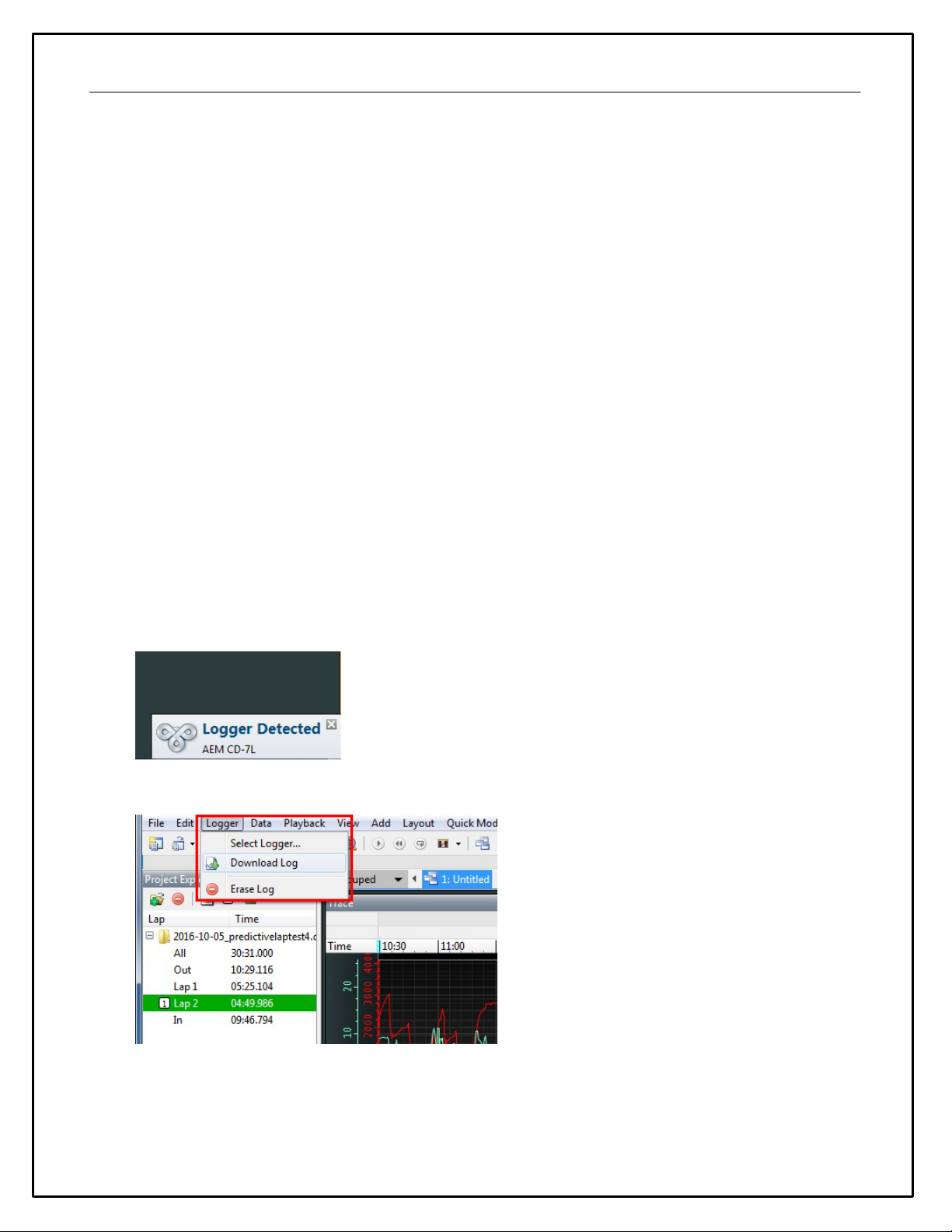
To download log files from an AEM CD-7L, connect the USB cable between the dash and your PC. Launch
AEMData analysis software and turn on the switched ignition power to the Dash. The message below will be
displayed when AEMData detects a connection to the dash.
Go to Logger | Download Log
If there are logs saved on the dash, a list similar to the one below will be presented. Select the files to
download. Choose whether to erase the files from the dash or not.
This manual suits for next models
7
Table of contents
Other AEM Measuring Instrument manuals

Popular Measuring Instrument manuals by other brands


Motcom
Motcom Data Indicator Pro user manual

Datcon
Datcon DT1102 V operating instructions

Tektronix
Tektronix Keithley SourceMeter 2461 user manual

Teledyne Lecroy
Teledyne Lecroy HVFO103 Operator's manual

Badger Meter
Badger Meter Oval Gear EPM2-STD user manual

Gossen MetraWatt
Gossen MetraWatt LonWorks U128-W1 Series Interface description


