FINEGEAR ARKIVE EFFECTS The Dust Collector User manual

ARKIVE_EFFECTS_
The Dust Collector
User’s Manual
version 1.0
April 2020

2
User’s Manual
The Dust Collector
INDEX
Introduction — 3
Overview — 4
Top — 4
Side — 5
Back — 5
Effects — 6
LFOs 1 & 2 — 6
Tape Saturations 1 & 2 — 7
Spring Reverb — 8
Delay — 9
Phaser — 10
Specifications — 11
Dimensions — 11
Weight — 11
Conventions — 11
Technical details — 11
Signal Paths — 12
LFOs — 12
Tape Saturations — 12
Spring Reverb — 12
Delay — 13
Phaser — 13

3
User’s Manual
The Dust Collector
INTRODUCTION
Finegear is proud to present arkive_effects_, a
curated series of effects designed for sonic
experimentation. The Dust Collector is the first of
the series, aiming to honor and expand upon the
history of experimentation in music, shaking some
of the dust that has settled on the 1970’s.
The Dust Collector contains 2 VC LFOs and 5 independent
audio effects: 2 tape saturations, a spring reverb, a delay
and a phaser. However, this is more than the standard multi-
effect box, as each module has been analysed and tweaked
to support your creative process. You can go further inside
with several moddable features directly on the PCB.
The Dust Collector will help you uncover unique sounds and
new uses for effects you thought you knew. You can insert
an effect in the delay’s feedback loop, add modulation to
the phaser (as well as to pretty much every effect), poke
the tank's three springy insides hiding behind the removable
acrylic cover.
This manual will describe in detail each effect and module,
as well as explain all the controls and interactions that are
possible with them. Useful technical information is also
provided, while signal path diagrams and calibration
procedures can be found in the annexes.

4
User’s Manual
The Dust Collector
OVERVIEW
Top
❶2x VC LFOs
❷2x Tape saturations
❸Spring reverb
❹Delay
❺Phaser
❻Reverb spring tank, with a
removable plexi cover.
13 VI. 5
6
2 4

5
User’s Manual
The Dust Collector
OVERVIEW
Side
❼Phaser LDRs with removable
plexi cover
7
Back
❶Phaser input and output
❷Delay input and output
❸Delay feedback loop insert
❹Spring reverb input and output
❺Tape Saturation 2 input and output
❻Tape Saturation 1 input and output
❼Power supply connector (5 mm
diameter, 2.5 mm pin)
❽Power switch
Note: All inputs, outputs and
inserts require 6.5 mono jacks,
unless stated otherwise.
1 2
3
4 5 6
7
8
6
User’s Manual
The Dust Collector
EFFECTS
LFOs 1 & 2
The two LFOs included in the Dust
Collector are identical, except
for the speed ranges, which differ
to broaden the sonic possibilities.
They were included to serve as a
starting point for modulating any
of the effects and/or the LFOs
themselves, without the need for
a modular setup (especially if one
is not available).
❶Speed:
Sets the speed of the LFO. The two
LFOs have different ranges in
order to allow as many modulation
combinations as possible.
speed min
(Hz)
max
(Hz)
LFO 1 0.17 7.5
LFO 2 0.56 25
❷Waveform selector:
Selects the output waveform between
sine, triangle and square.
❸Speed modulation CV
input
Input for modulating the speed of the
LFO using a CV (3.5 mm jack.)
❹Speed CV modulation
amount
Sets the amount of modulation from
the CV input (❸) that will affect the
LFO’s speed.
❺Speed CV modulation
indicator
Bi-colour LED providing visual feedback
of the CV input’s (❸) value.
❻CV outputs 1 & 2
Two identical LFO outputs.
❼Inverted CV output
Outputs the inverted LFO using a CV
(3.5 mm jack).
❽Output bi-coulour LED
indicator
Bi-colour LED providing visual feedback
of the LFO’s output value.

7
User’s Manual
The Dust Collector
EFFECTS
Tape Saturations
1 & 2
The two “tape” saturations were
included to help spice or dirty up
sounds before or after passing
through the other effects.
The saturation effect ranges
from very subtle (type i) to more
saturated and compressed (type v).
In the Dust Collector this is achieved
through analog electronics
exclusively, without any real tapes.
❶Type:
Sets the type, i.e. intensity of the
saturation effect. The further the type
knob is turned to the right, the more
pronounced the effect.
❷Output volume:
Selects the output waveform between
sine, triangle and square.
❸Bypass switch:
Bypasses the effect.
DIY tip: The schematics for
the Tape Saturations are based
on five pairs of diodes. The Dust
Collector uses one pair of 1N4148
and four pairs of 1N60 diodes.
Different diode models can be
mixed and matched for (slightly)
different saturation effects.
8
User’s Manual
The Dust Collector
EFFECTS
Spring Reverb
Besides having the classic spring
tank sound, the spring reverb was
integrated into the Dust Collector
design to allow extensive interaction:
•
direct physical interaction with
the springs, thanks to the
removable plexi cover .
• extended modularity, thanks
to input and output CV
controllable VCAs.
❶Input VCA level:
Sets the input VCA’s level.
❷Input VCA modulation
CV input:
Input for modulating the input VCA
with a CV (3.5 mm jack).
❸Input VCA CV
modulation amount:
Sets the amount of modulation from
the CV input (❷) that will affect the
input VCA.)
❹Input VCA CV
modulation indicator:
Bi-colour LED providing visual
feedback of the input VCA’s CV input’s
(❷) value.
❺Output VCA level:
Sets the output VCA’s level.
❻Output VCA modulation
CV input:
Input for modulating the output VCA
with a CV (3.5 mm jack).
❼Output VCA CV
modulation amount:
Sets the amount of modulation from
the CV input (❻) that will affect the
input VCA.
❽Output VCA CV
modulation indicator:
Bi-colour LED providing visual
feedback of the output VCA’s CV input’s
(❻) value.
❾Tone control:
Sets the tone of the signal before
the output VCA and after the signal
is amplified by the recovery amp.
Tone control is obtained thanks
to a shelving filter: to the left, the
bass frequencies are amplified
and the treble is reduced, while
to the right, the treble is amplified
and the bass is reduced.
❿Dry/wet mix:
Sets the balance between the input
signal (dry/clean) and the output
signal (wet/processed).
⓫Spring tank removable
cover:
The spring tank has a transparent
plexi cover. Remove it using the
thumb screws, to scratch, hit, rub,
place various objects on the springs…
11

9
User’s Manual
The Dust Collector
EFFECTS
Delay
The included delay takes pride in its
dirty and raunchy sound, as well as
in its modulation potential. It has a
temper and you can modulate it!
The Dust Collector delay circuit is
based on the PT2399 echo chip
from Princeton Technologies. It is a
slightly cleaned-up version of the well-
known gritty sound of the classic
delay chip, with several additions
enhanced with:
• a CV modulated delay time;
• an insert in the feedback loop;
•
a momentary “Madness” switch
to max out the feedback.
•
❶Time:
Sets the module's delay time.
❷Feedback:
Sets the amount of output signal
to be fed back into the input.
❸Madness switch
(momentary):
Momentary switch, sets feedback
to maximum for immediate delay
build-ups.
❹Time modulation CV
input:
Input for modulating the delay’s time
with a CV (3.5 mm jack).
❺Time CV modulation
amount:
Sets the amount of modulation from
the CV input (❷) that will affect the
delay time.
❻Time CV modulation
indicator:
Bi-colour LED providing visual
feedback of the delay time’s CV
input’s (❻) value.
❼Dry/wet mix:
Sets the balance between the input
signal (dry/clean) and the output
signal (wet/processed).
❽Insert (back side):
The delay has an insert point in the
feedback loop, allowing any effect
to be inserted in order to alter the
echoed sound before reinjecting it
in the Delay again.
8
10
User’s Manual
The Dust Collector
EFFECTS
Phaser
The Dust Collector Phaser is based
on a classic model from the 1970s
and it too is designed with extensive
modulation potential, using both of
the LFOs, a knob and/or a CV input
and even ambient light...
This model uses LDRs
1
and LEDs
to modulate the sound. This is the
reason why this combination of
LDRs and LEDs has been placed
close to the edge of the PCB, and
a hole has been designed in the
enclosure next to the sensors. The
hole is covered with a black opaque
plexi cover and, when removed, the
Phaser can be modulated using
ambient light: move a hand in front
of the hole or use any other light
source and place it near the hole to
modulate the phaser in a new and
unique way.
❶Feedback:
Sets the Phaser’s feedback.
❷Modulation amount/
manual depth:
Sets either the modulation amount
if the Modulation selector is set on
LFO 1 or LFO 2, or, if the selector is
on Manual, it becomes the manual
depth knob.
❸Depth bi-colour LED
indicator:
Bi-colour LED providing visual
feedback of the phaser’s depth
value: obtained by adding the
modulation from LFO 1 or 2 or the
manual value with the CV input’s
(❹) value.
❹Modulation selection
switch:
Sets the phaser’s internal
modulation mode and modulates
the Phaser’s depth. If either LFO is
selected, the Depth (❷) knob sets
the modulation amount from the
selected LFO.
1LDR - light dependent resistor, a sort of
light sensor.
If the switch is set on Man (manual
mode), the Depth (❷) knob itself
sets the Phaser’s depth, serving
either as an offset for the CV
modulation, or for manually altering
the depth to create humanized
modulations.
❺Depth modulation CV
input:
Input for modulating the phaser’s
depth with a CV (3.5 mm jack. This
CV value is added to the modulation
set by the Depth (❷) knob.
❻Depth CV modulation
amount:
Sets the amount of modulation from
the CV input (❺) that will affect the
phaser’s depth.
❼Dry/wet mix:
Sets the balance between the input
signal (dry/clean) and the output
signal (wet/processed).
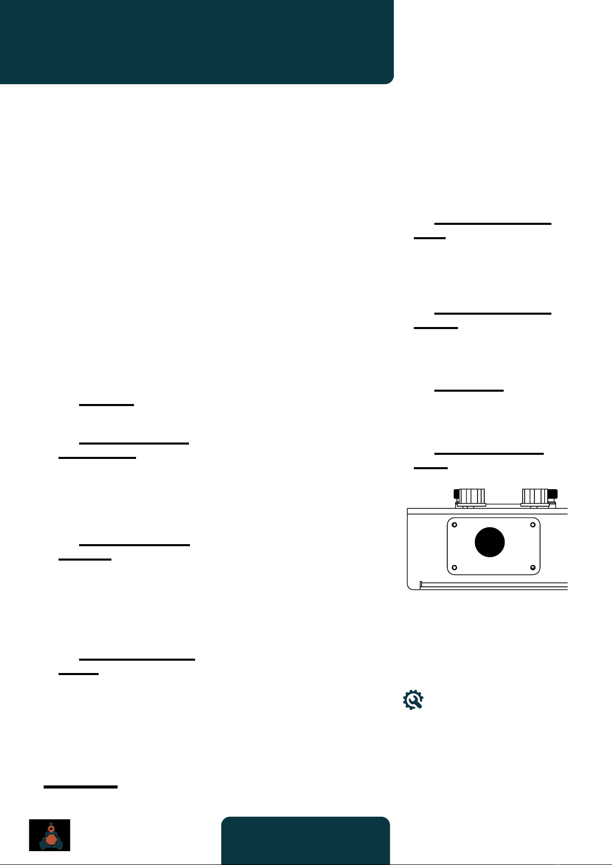
❽Light sensors panel
(side):
This panel can be removed to
modulate the phaser with “custom”
light sources and/or mechanical
means in order to enhance the
“movement” of the phased signal.
DIY tip: experiment with
different coloured LEDs for
(slightly) different phasing
effects.
8

11
User’s Manual
The Dust Collector
SPECIFICATIONS
Conventions
While you play the Dust Collector,
please remember that:
L
Bi-colour LEDs are used to
indicate certain bi-polar CV
values. They’re coloured
red and green and they are
connected such that
red = negative CV voltages
green = positive voltages.
L
Delay: the insert jack is a
connected type, where the
tip = send
ring = return.
Technical details
ѣLFOs CV output range:
-5 V — 5 V.
ѣ
Power supply: 24 V, 1 A,
center positive supply, with a
5.5 mm diameter and 2.5 hole
connector.
ѣ
Spring tank: Accutronics
model 8AB2D1A.
ѣ
Delay : based on the PT2399
memory chip from Princeton
Technologies.
ѣ
Phaser LDRs : model 5516
with yellow LEDs.
Dimensions
• Width : 341 mm
• Depth : 313 mm
•
Height : 57 mm (box only),
70.5 mm (including the knobs)
Weight
• 2,6 kg.

12
User’s Manual
The Dust Collector
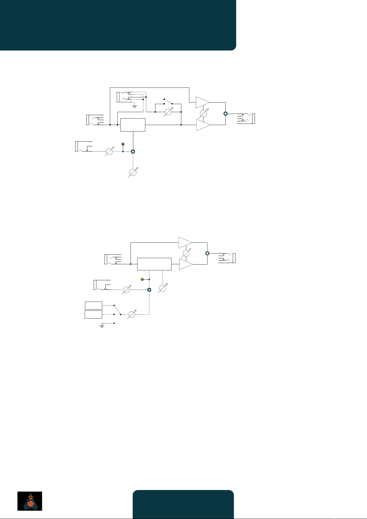
SIGNAL PATHS
LFOs
Tape Saturations
Spring Reverb
CV
SPEED
-1
WAVEFORM
LFO
SPEED
CV INPUT
LFO
OUT 1
LFO
OUT 2
LFO
OUT 3
INV
LFO OUT
CV IN
TYPE
LEVEL
BYPASS
TAPE
SATURATION SATURATION
OUTPUT
SATURATION
INPUT
IN LEVEL
CV IN
OUT LEVEL
CV OUT
TONE
DRY/WET
MIX
SPRING
REVERB
INPUT
CV IN
CV OUT
SPRING
REVERB
OUTPUT
INPUT
VCA
SPRING
DRIVER SPRING RECOVERY
AMP
TONE
CONTROL
OUTPUT
VCA
CV IN
CV OUT
13
User’s Manual
The Dust Collector
SIGNAL PATHS
Delay
Phaser
DELAY TIME
CV IN
INSERT
FEEDBACK
MADNESS
DRY/WET
MIX
DELAY
DELAY
INPUT
CV IN
DELAY
OUTPUT
CV
FEEDBACK
CV IN
MODULATION
DEPTH
DRY/WET
MIX
PHASER
PHASER
INPUT
CV IN
LFO 1
LFO 2
PHASER
OUTPUT
MOD

Other manuals for ARKIVE EFFECTS The Dust Collector
1
Table of contents
Popular Recording Equipment manuals by other brands


Extron electronics
Extron electronics IP Link Series user guide

Mitsubishi Electric
Mitsubishi Electric DX-NT400E Operation quick guide

CHROMATEQ
CHROMATEQ PRONET-E quick start guide

Ecler
Ecler VEO-DACS4 user manual

Panasonic
Panasonic WJHD316A - DIGITAL DISK RECORDER Specifications

X-10
X-10 POWERHOUSE CP290 owner's manual