finetech FINEPLACER lambda User manual

FINEPLACER®lambda
Sub-Micron Bonding System
Operator’s Manual
Finetech GmbH & Co. KG
Boxberger Str. 14
12681 Berlin
Service +49 (0) 30 93 66 81-350
Fax +49 (0) 30 93 66 81-144
service@finetech.de
All specifications and characteristics are subject to change without notice.

FINEPLACER®lambda
Rev-Nr. 1.1
2
Content Page Content Page
1 HINTS FOR USING THIS MANUAL 4
2 GENERAL INFORMATION ON
FINEPLACER® SYSTEMS AND THIS
MANUAL 4
2.1 APPLICATION OF THE
FINEPLACER® LAMBDA 4
2.2 OPERATING PRINCIPLE,METHOD OF
WORKING AND SYSTEM FEATURES 6
2.3 METHOD OF WORKING,POSITIONING
AND PLACEMENT 7
2.4 PURPOSE OF THE EQUIPMENT;
WARNING AGAINST MISUSE;
WARRANTY CONDITIONS 7
2.5 GENERAL SAFETY INSTRUCTIONS:
MASS/WEIGHT 8
2.6 SAFETY REGARDING ELECTRICAL
MAINS POWER 9
2.7 ELECTROSTATIC DISCHARGE,
ELECTROMAGNETIC COMPATIBILITY 10
2.8 HEAT AND FIRE HAZARDS,RISK OF
BURNS 10
2.9 CONDITIONS OF WORK AREA;OTHER
POSSIBLE HAZARDS 11
3 THE FINEPLACER® SYSTEM 13
3.1 INTRODUCTION 13
3.2 MAJOR ASSEMBLIES OF THE BASIC
EQUIPMENT 13
3.2.2 SUPPORT ARM (71), HOLDING THE
FOLLOWING PARTS: 16
3.2.3 PIVOT ARM (27) 16
3.2.4 PLACER CONTROL BOX 17
3.3 SHORT DESCRIPTION OF BASIC
FUNCTIONS AND DIRECTIONS FOR
INSTALLATION 18
3.3.1 MAINS CONNECTION 18
3.3.2 DISPLAYS AND OPERATING ELEMENTS18
3.3.3 GENERATION AND CONNECTION OF
VACUUM AND COMPRESSED AIR 19
3.3.4 PLACER SUPPORT 19
3.3.5 CAMERA CONTROL AND POWER
SUPPLY FOR OPTIONS 19
3.3.6 RS-232 INTERFACE 20
3.3.7 FINETECH MODULE INTERFACE 21
3.4 OPERATING INSTRUCTIONS FOR THE
PLACER CONTROL BOX 21
3.4.1 SWITCHING ON 21
3.4.2 CONTROLLING THE BRIGHTNESS 22
3.4.3 UNDERSTANDING THE VACUUM
CONTROL 22
3.4.4 VACUUM CONTROL SAFETY SYSTEM 23
3.5 PARTS,CONTROLS AND INDICATORS 23
4 INSTRUCTIONS FOR SET-UP27
4.1 INITIAL SET-UP OF THE
FINEPLACER® 27
4.1.1 PREPARATION OF THE BASIC
COMPONENTS AND SUBASSEMBLIES 27
4.1.2 PREPARATION OF THE POSITIONING
TABLE'S HEIGHT ADJUSTABLE
TRACKS 27
4.1.3 PROVIDING SUITABLE PLACEMENT
HEADS FOR THE PIVOT ARM 28
4.1.4 INTERCONNECTION OF THE LAMBDA 28
4.1.5 PRELIMINARY SETTINGS AND
CHECKOUT 29
4.2 ADJUSTING THE PLACEMENT
ACCURACY OF THE LAMBDA29
4.2.1 REQUIRED TOOLS: 30
4.2.2 DISTINGUISHING BETWEEN LAMBDA
A6, A7 AND A7+ 30
4.2.3 ADJUSTING THE PLACEMENT
ACCURACY 30
4.3 ADJUSTING THE PLACEMENT ARM'S
COPLANARITY 35
5 OPERATING INSTRUCTIONS 38
5.1 ADJUSTABLE LOCK POSITION FOR THE
MANUAL OPTICS SHIFTING 38
5.2 LOADING THE COMPONENT FOR
PLACEMENT 39
5.3 ALIGNMENT 39
5.4 PLACEMENT 39


FINEPLACER®lambda
Rev-Nr. 1.1
4
1Hints for Using this Manual
Please read the safety instructions first before operating the FINEPLACER®
•Have a look at the pictures before reading the operating instructions to
familiarize yourself with the FINEPLACER®. Start with the basic machine and
do the same with each module belonging to your special system configuration.
•Read the operating instructions.
•Read the maintenance instructions.
•Learn more about the most important points for avoiding problems.
•In case of defects, and before dismantling anything, contact your dealer or the
manufacturer.
•Perform the same procedure for all other optional module-concerned parts
attached after part A.
2General Information on FINEPLACER®Systems
and this Manual
This manual will be updated regularly, however, it is possible that it does not cover all
the details of your equipment accurately, subject to errors and technical changes,
especially those made on a customer's request. For optional modules, see also
specific manual sections.
Assured properties must be agreed upon by contract expressly and in writing.
The trade name 'FINEPLACER®' is now registered with Systems 2000 GmbH within
the United States of America.
2.1 Application of the FINEPLACER®lambda
The lambda is designed to position fine pitch devices e. g. Flip Chips and Flip Chip
assemblies, optoelectronic components, micro electro mechanic systems (MEMS),
micro optoelectronic mechanic systems (MOEMS), sensors, micro optics, TAB, bare
chips and other high-count surface mounted devices (SMD). The FINEPLACER®
System is based on a unique placement principle integrated into five machine models
according to the type and sizes of the various components and substrate dimensions.
Using the highly accurate Vision Alignment System (VAS), the FINEPLACER®lambda
is designed to accurately place the component on the first attempt. As its accuracy is
1 µm, it is possible to position new technology components with very fine pitch
uniformly and accurately.

FINEPLACER®lambda
Rev-Nr. 1.1
5
Optional accessories include special optics for positioning large fine pitch devices on
their substrates and high magnification systems for observing chip bonding. All state
of the art bonding technologies can be performed, such as thermocompression,
ultrasonic/thermosonic bonding, ACF bonding, UV cure and bonding of C4 chips. Due
to the modular system, the necessary configuration may easily be optimized,
corresponding to your individual requirements. As every FINEPLACER®, the lambda
allows cost effective and safe manual component placement and bonding at one
work station and in the same operation.
FINEPLACER®lambda
Rev-Nr. 1.1
6
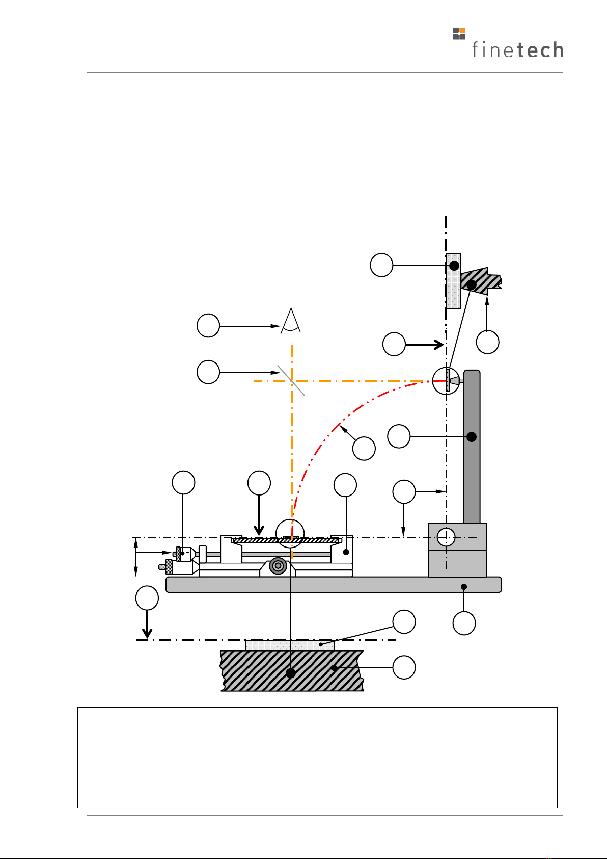
2.2 Operating Principle, Method of Working and System
Features
The patented advanced Vision Alignment System of the lambda is based on the
principle of imaging two orthogonal images simultaneously into one common image
plane, using a stationary beam splitter (30) and a single beam deflection (see fig. 1):
Fig. 1: Operating principle of A6/A7 (sketch of the lateral view, right hand side)
A Observation point (camera) B Working level
C Bottom glass scale or substrate D Surface of the heating
E UAP Upper Arm Position F Top glass scale or component
H Working level and UAP must form angle of 90°
A
F
H
30
C
B
51a
E
B
70
D
27
29
G
20

FINEPLACER®lambda
Rev-Nr. 1.1
7
The configuration shown in fig. 1 allows orthogonal view of the objects
component (F) and substrate (C), so both are seen to be observed "vertically from
above" (A). The overlay image allows a comparison of all connectors on each
component lead with each substrate pad at a glance.
2.3 Method of Working, Positioning and Placement
To adjust the positioning table (29) manually, observe the dual image overlay
through the video system. Coarse align using the air cushion, fine align by means of
the micrometer screws. Angular deviations are eliminated by turning the positioning
table around an electromagnet mounted in the optical axis.
Shift the video optics to the right-hand end position and place the component held in
the positioning head (F) on the substrate (C) by simply swinging down the pivot
arm (27) following the curve (G). To release the component, switch off the
placement head's vacuum by pressing the vacuum foot switch.
FOR AN ACCURATE PLACING IT IS AN ESSENTIAL PRECONDITION,
•THAT THE TABLE HEIGHT HAS BEEN BROUGHT INTO THE WORKING LEVEL(B) WITH THE HELP
OF THE MICROMETER SCREW (51A)AND THAT THE UPPER ARM POSITION (UAP) HAS BEEN
ADJUSTED AS DESCRIBED IN 4.2.2, SO THAT LEVEL (B) AND (E) FORM AN RIGHT ANGLE.
•THAT THE BEAM SPLITTER (30) HAS BEEN ADJUSTED CORRECTLY AS DESCRIBED IN 4.2.3.. IT
IS NOT NECESSARY TO PERFORM THE ADJUSTMENT PROCEDURE BEFORE EACH WORKING
PROCESS BUT TO CHECK IT OCCASIONALLY.
2.4 Purpose of the Equipment; Warning Against Misuse;
Warranty Conditions
The FINEPLACER®equipment is intended only for industrial and skilled trade use and
must be run and serviced by qualified personnel only. Everyone must observe the
caution, circumspection, and responsibility required to run this equipment, consisting
of mechanical, optical, mains powered, electromechanical and electrical heating
appliances, and possibly using compressed air or an inert gas. Operators must not be
under the influence of alcohol or other drugs and must not allow their attention to be
distracted.
FINEPLACER®equipment is designed to be used solely for work on components and
substrates in the way intended in a configuration agreed with Finetech and together
with Finetech approved equipment. In other cases it must be expressly agreed in
writing with Finetech GmbH, Berlin, Germany, under the conditions stated in the
manual. Any other use, changes, use of foreign controls or procedures not laid down
in this manual may cause risks. Any single, complete FINEPLACER®Base Module in
proper working condition, with or without additional optional Finetech modules, is
considered to be one apparatus. Modules are not considered to be independent

FINEPLACER®lambda
Rev-Nr. 1.1
8
equipment and must not be run without being combined with our Base Module as
specified.
National and international standards and regulations for minimizing the risk of
serious injury are, as far as possible, taken into account in the development and
production of this equipment as applicable to ("Conformity", "CE"), but danger
caused by improper use or by breakdown remains.
The operator of the equipment is responsible for carrying out safety checks as stated
in the manual and should not hinder or diminish these by conditions of the working
place and its surroundings.
Manufacturer and contractor are not liable for damages or injuries caused by
improper use or unsuitable work.
The FINEPLACER®comes with a year’s guarantee that equipment will be free from
malfunctioning, material defects, and manufacturing faults, under the condition that
the equipment is used for its intended purpose only and under the specified
conditions of use, and does not extend to tools, wear and tear, glass, bulbs and
rubber parts. During the guarantee period, equipment that does not work perfectly
will be repaired or exchanged free of charge.
The guarantee only covers the aforementioned FINEPLACER®equipment, but no
consequential damage of any kind arising from breakdown, malfunction or improper
use of the equipment.
2.5 General Safety Instructions: Mass/ Weight
Some of the FINEPLACER®modules are heavy and may cause damage or be
damaged by inattentive transportation or use.
Before setting up the system, make sure that the working table can bear sufficient
load to carry the machine and its accessory. Further, check if the table is mounted in
a technically correct manner. In case of using a height adjustable table, check the
safety clamping of the height adjustment mechanism. Commercial damage or
personal injury caused by neglecting the above safety measures is not covered by
Finetech's responsibility.
Arrange cables and hoses so that nobody can get caught.
If you want to move the machine, first disconnect all cables and hoses and take the
positioning table off the base plate.
Before moving the air-bearing positioning table both hands have to be placed at the
table.
Press the pedal to move the table and keep both hands always at the table while
moving it around.

FINEPLACER®lambda
Rev-Nr. 1.1
9
Under no cirscumstances press the pedal unless both hands are on the
positioning table. Risk of damage or injury.
With activated air cushion, the positioning table’s outer edges can be moved beyond
the edges of the base plate.
Make sure that the table is not placed in an extreme position that is unsuitable for
work.
Damage can occur here due to incorrect behavior of the operator (by leaning or
putting weight on the table).
Make sure the base plate has been adjusted correctly (see 3.2 Major Assemblies of
the Basic Equipment).
2.6 Safety Regarding Electrical Mains Power
Be cautious of electrical hazards:
No wet hands, no children, no plants and no animals should come into contact with
any machine part. Always keep the equipment dry. No thin or small electrical
conducting parts (e.g. cut wires, washers) should come in the close vicinity of the
machine's electrical equipment, into connectors, or especially into ventilation slots.
Before you disconnect from the mains:
•Lay down the pivot arm and switch OFF the electrical power.
•To connect the mains, first put the (female) plug into the control box socket,
and then the other (male) plug into the (wall) outlet; disconnecting in reverse
order.
•Never pull/push leads and hoses with the lead outside the plug. Always hold
the plug in your hand.
Two-handed handling of the positioning table

FINEPLACER®lambda
Rev-Nr. 1.1
10
Protect power cords from being stepped on, driven over, crushed, cut, split etc.
especially when they are live. Only use power cords with an earth contact. Before
connecting to the mains, check the correct voltage (see technical data)!
Before changing lamps, switch off the power and wait for it to cool down.
Before changing fuses find the cause of the fault, and pull out the mains power plug!
In case of equipment trouble, switch off the mains power and call for qualified
maintenance personnel.
Electrical equipment casings must only be opened by a qualified electrician!
If using a computer to run FINEPLACER®Modules, we recommend that it is not
supplied by the mains outlet of the placer control box to prevent unintentional shut
down of the computer when turning off the FINPLACER®Modules.
2.7 Electrostatic Discharge, Electromagnetic Compatibility
Protection of ESD sensitive devices is the responsibility of the user. This means that
the FINEPLACER®has to be operated in an ESD protected area (EPA according to
IEC 61340) in any cases when ESD sensitive devices are handled. The equipment is
prepared in so far as electrostatic charges are deflected to the ground terminal.
FINEPLACER®s and their modules conform to EC Directive of Electromagnetic
Compatibility (EMC).
Magnetic fields being beyond the limits of the above directive could anyhow influence
the function of Finetech heating modules resulting in temperature deviation or
unexpected program stops.
2.8 Heat and Fire Hazards, Risk of Burns
Heating plates and other heating accessories may cause heat and fire hazards by
improper use and in the case of equipment defects. Therefore, heating equipment
must only be worked under supervision and be switched off if not in use.
During operation, heating plates, lamps and their adjacent parts may become hot; up
to approximately 400°C, and should not be touched, please use suitable tools.
Heating modules may damage substrates and devices in the case of excessive
temperature/time dosage, especially if heating plates are used. Excessive heat may
produce fumes or smoke resulting in health hazards. Therefore, measure heat
carefully, especially when using the manually controlled modules, and stop heating in
good time. Increase temperature and time settings cautiously so as not to damage
components and substrates.
Never run FINEPLACER®heating modules differently from rules given in the instruc-
tions! Never use their heat abusively against people or heat sensitive
material! Keep the direct flow of heated gas away from people and temperature
sensitive parts!

FINEPLACER®lambda
Rev-Nr. 1.1
11
If there is any sign of increasing overheating (if display shows values much higher
than set value, or heating period is longer than programmed, or ERROR light comes
on etc.), switch off the equipment and call for qualified maintenance personnel!
Heating should be stopped in case of danger caused by any heated modules. This
can be done by erecting the pivot arm, pushing the STOP key, or switching OFF the
module itself immediately (see the respective module instructions).
As long as the pivot arm is erected, the heating should not be able to be switched
ON (so as not to warm up the optics unnecessarily).
2.9 Conditions of Work Area; Other Possible Hazards
On installation of the equipment, please carefully inspect the surrounding area for
possible dangers arising for people, equipment, or work pieces.
Environmental temperature conditions below 15°C or over 35°C should be avoided
during work with the FINEPLACER®. Lower temperatures could cause functional
trouble, higher temperatures could cause overheating of the control circuits - ensure
sufficient cooling breaks. Temperature changes could influence the positioning
accuracy.
Because of the high optical magnification required in some cases, intensity and beam
concentration of the built-in illumination equipment may be rather high. On installing
and running the FINEPLACER®beware of dazzling the eyes of the operator or people
in the vicinity.
Always take care to avoid condensing water.
The optionally mounted Target Finder's Laser beam is directed downwards. During
normal operation it only runs for short periods of time and is fundamentally not
hazardous because of its low power (< 1 mW, c l as s 2 product). However, you should
avoid looking directly into the beam. Dazzling might be caused by unfavorable
circumstances such as multiple reflections on metallic support plates.
Install hoses and electrical cabling free of mechanical tension and so as not to catch
someone or to tear down parts of the equipment.
Hoses as well as compressed gas couplings and connectors should be handled
cautiously and with care and protected against damage. Protect eyes and ears when
connecting or disconnecting live gas hoses.
In case of using inert gases, insure there is sufficient ventilation of the working area!
The pressure of compressed gas for cooling purposes should be set to an adequate
level so as not to exceed a tolerable noise level. If this is not possible, use ear
protectors.

FINEPLACER®lambda
Rev-Nr. 1.1
12
ATTENTION!SUPPLY MEDIA LIKE,E.G., COMPRESSED AIR OR INERT GAS,MUST HAVE A QUALITY
ACCORDING TO THE STANDARDS DEFINED IN DIN ISO 8573-1, CLASS 4, WITH REGARD TO OIL,
WATER,AND PARTICLE CONTENTS.OTHERWISE,SERIOUS MALFUNCTIONS MUST BE EXPECTED AND
PARTS OF THE EQUIPMENT CAN BE DAMAGED.ANY DAMAGE DUE TO INSUFFICIENT MEDIA PURITY WILL
NOT BE COVERED BY WARRANTY
.
Comply with the special safety conditions given with the descriptions of the modules.
With the Finetech Bonding Force Applicators in particular, beware of bruising fingers
or damaging the work piece.
Air purity according to DIN ISO 8573-1, Class 4, stands for the following demands:
•Particle size 15 µm
•Particle density 8 mg/m³
•Pressure dew-point 3°C
•Water content 6000 mg/m³
•Oil content 5 mg/m³

FINEPLACER®lambda
Rev-Nr. 1.1
13
3The FINEPLACER®System
3.1 Introduction
Like every FINEPLACER®, the lambda has been designed for versatile use and ease
of operation and maintenance, and is made up of functional modules. The operator
should thoroughly understand the function and control of each module and tool in
the system before using it.
The numbers of machine parts given in brackets correspond to the numbers in table
2 of this text.
The Flip Chip Bonder consists of the following parts:
•Base Module with base plate (70), support arm (71), stationary beam splitter
optics (30), illumination, camera (18) and positioning table (29), further placer
Control Box (39), table foot switch (64) and vacuum foot switch, as well as
cables and hoses.
•Vision modules, e.g. or MIRAGE (37) or side camera with common video
monitor.
•Process Modules, e.g. placer arm (27) with positioning head (20), Ultrasonic
or ACF Module.
•Auxiliaries, e.g. optional pipette (24) or Target Finder.
FINEPLACER®s may be additionally equipped with various optional modules, mostly
to be retrofitted easily to adapt to customer's requirements.
3.2 Major Assemblies of the Basic Equipment
3.2.1.1 Base Plate (70)
The base plate carries the support arm (71) and the pivot bearing with the pivot arm
(27). Optionally it is possible to add an ultrasonic transducer to the pivot arm.
The base plate serves as the highly precise finished gliding plane for the positioning
table (29), and also contains an electromagnet which holds the table in position
when the air cushion is deactivated and allows the θfine rotation.

FINEPLACER®lambda
Rev-Nr. 1.1
14
The base plate rests on foot screws which are used to level it.
Align the base plate in a way that it slightly slopes backwards, away from the
operator.
The incline should be between 0.1 mm/m and 0.3 mm/m.
Use a circular level for alignment.
Alternatively, use a spirit level.
Make sure there is no horizontal tilt.
The table should always slowly slide away from the operator towards the machine
when the air cushion is activated. After adjusting the angle of slope, test this
movement carefully with both hands on the positioning table.
Example: Machine base plate, adjusted with spirit level
Example: Machine base plate, adjusted with circular level
Foot screw at base plate
FINEPLACER®lambda
Rev-Nr. 1.1
15
It is strictly prohibited to work with the machine before this setting has been made!
3.2.1.2 The Height Adjustable Positioning Table
•... rests on the base plate (70). It carries the height adjustable tracks used to
clamp in a substrate, a substrate support plate or a FINEPLACER®heating
plate to hold the substrate.
•... will secure the substrate position by its mass and its friction against the
base plate (70), supported by the electromagnet buried in the base plate.
•... can be moved easily for coarse positioning on an air cushion so that it may
float above the base plate (70), using the micrometer screws (50) and (51) as
temporary handles. Once coarse positioning is achieved, releasing the foot
switch will lock the table in the optical axis.
•... can be fine aligned using the x and y micrometer screws.
•... can be rotated around the optical axis to achieve θcorrection, prevented
against accidental x or y shifting by the electromagnet.
A fundamental rule is that the height of the placement surface of the substrate must
be equal to that of the pivot arm axis. To achieve this with substrates to be laid onto
heating plates or support plates, the continuously height adjustable tracks of the
positioning table have to be used to maintain the correct working height.
Table movement direction with activated air cushion

FINEPLACER®lambda
Rev-Nr. 1.1
16
3.2.2 Support Arm (71), holding the following parts:
•Vision/observation devices, basically consisting of the stationary mounted
beam splitter optics (30), providing the dual image overlay, and a video option
for vertical view, are used to view the super-imposed image of the substrate's
pads and the corresponding component leads.
•Lighting: COAX-Illumination and diffuse illuminationis standard, a Target
Fínder (AC1) is integrated.
•The pivot bearing for the pivot arm (27). Zero play of the bearing and stiffness
of the arm are fundamental for the lambda's outstanding placement accuracy.
•The connector for electromagnet, and air for the table (4).
•The adjustment means for beam splitter (31), (32), arm-UAP (72) and arm-
LAP (89).
•Target Finder (AC1), pointing to the placement area (TARGET) on the
substrate.
•Optional: Force Applicators (e.g. FD2).
3.2.3 Pivot Arm (27)
The pivot arm may be e.g. a pivot arm (27); further special arms are available, e.g.
FE1. for ultrasonics application (chip bonding). Pivot arms have their own cables and
hoses for energy transportation and control. Each arm is equipped with a hose for
the vacuum holding the component to be placed in the positioning head, e.g. (20),
and signal cabling for arm tilt switch. The tilt switch sensing the arm position,
(erected or laid down), influences many equipment functions, e.g. switching vacuum
by pipette.
The arm is only mounted to the pivot log by 2 screws (148) so it may be changed
easily if required.
Fine-θ-Adjustment-pivot arms are available.
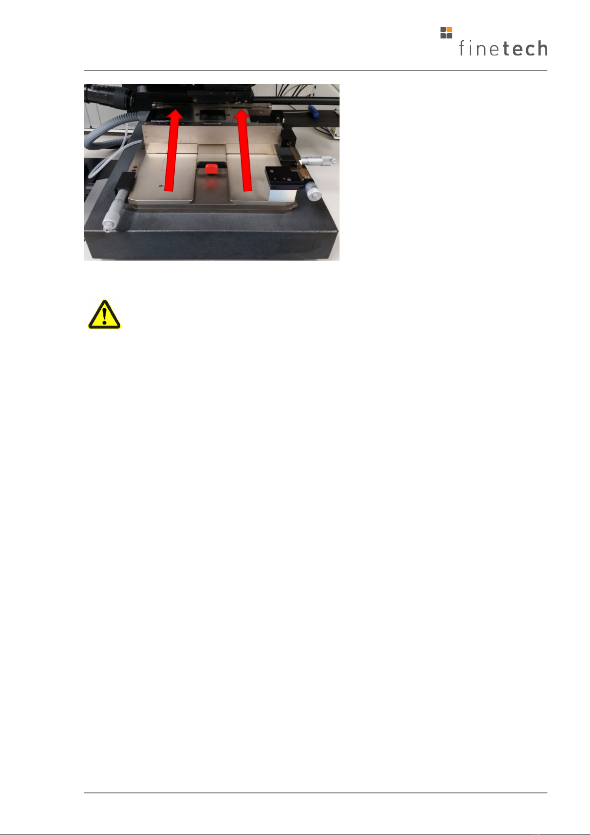
Attention: Pivot Arm Interlock (for manual configurations)
For FINEPLACER®lambda systems in manual configuration, a specific magnetic
interlock mechanism ensures that the pivot arm can only be swivelled down as long
as the optics shifting is in swivel position.
This safety function prevents the pivot arm from swivelling down and possibly hitting
and damaging the optics while the optics shifting is not in swivel position.
FINEPLACER®lambda
Rev-Nr. 1.1
17
3.2.4 Placer Control Box
The Placer Control Box is an essential part of any FINEPLACERBasic Module. It
generates and reacts to all signals for operating the placer, as well as supplying it
with compressed air and a vacuum.
The Placer Control Box contains the following basic functional groups:
1. mains connection
2. displays and operating elements
3. generation of vacuum for fixing devices and compressed air for the
positioning table air cushion
4. placer support, consisting of:
•lighting control
•supervision of pivot arm
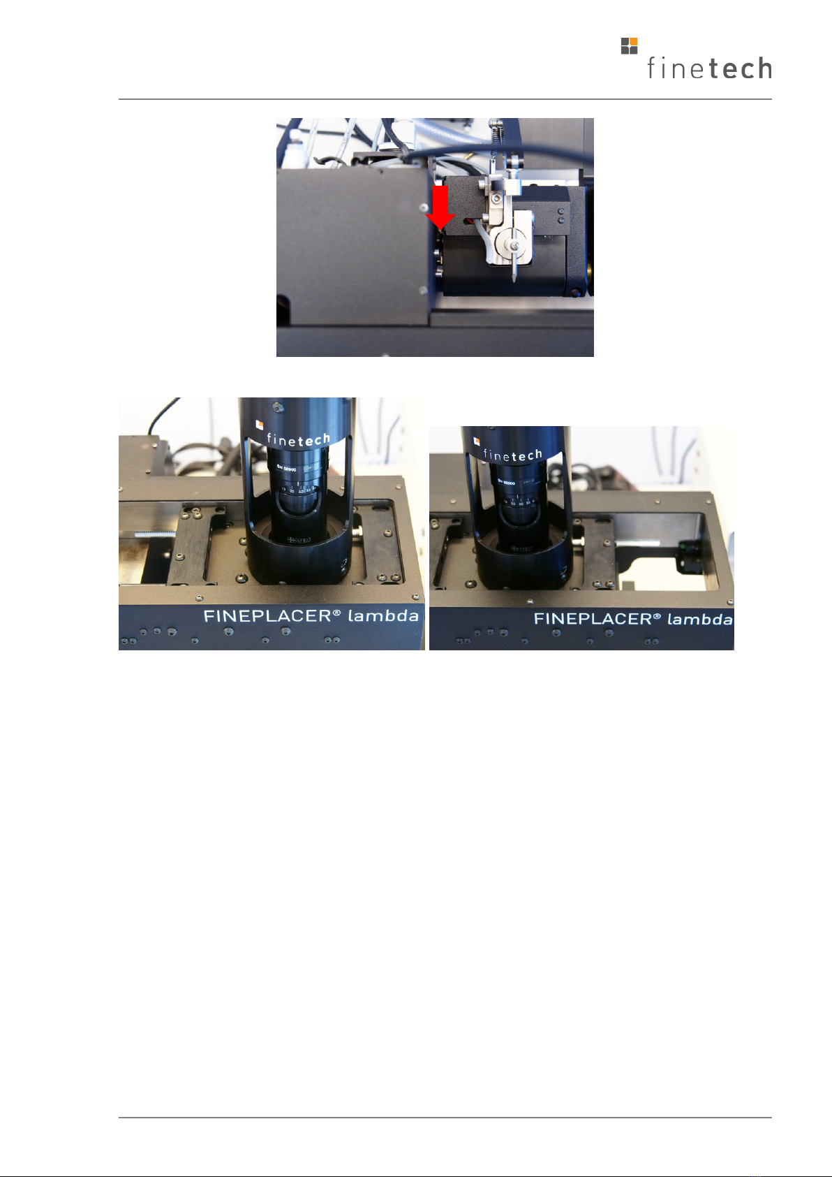
Magnetic interlock
Optics shifting in swivel position. Pivot arm
can be swivelled down.
Optics shifting in working position (each
position apart from swivel position).
Pivot
arm cannot be swivelled down.

FINEPLACER®lambda
Rev-Nr. 1.1
18
•locking electromagnet control
•Target Finder control
5. camera control and power supply for options
6. RS 232 interface
7. Finetech Module Interface (FMI) for connecting Finetech modules
3.3 Short Description of Basic Functions and Directions For
Installation
3.3.1 Mains Connection
The Placer Control Box has to be connected to the mains via the POWER IN plug in
the rear panel of the box using the supplied cable.
As soon as the Placer Control Box is switched on, the rear mains outlet AUX POWER
OUT is energized. Please connect all additional control boxes via the supplied
multiple box plugged into AUX POWER OUT so all FINEPLACER-modules are
switched on at the same time.
Check your mains voltage! The box must not be connected to mains
voltages different to those indicated on the rear panel's type plate.
The socket 'POWER IN' contains a fuse which exclusively serves to protect the Placer
Control Box but not all the other control boxes connected to the multiple socket.
Please take care never to exceed the maximum output current of 10 A
at 230 V or 15 A at 115 V (resistive load) respectively delivered by the
AUX POWER OUT socket.
There are two different green LED's. The LED 'LINE' indicates the presence of the
mains voltage whereas the LED 'ON' shines as soon as the equipment is switched on.
3.3.2 Displays and Operating Elements
The LED 'VACUUM STATUS' and the interior red lit switch 'VACS OFF' is used for
indication and further control of the vacuum. More detailed information about the
meaning and function of these elements is given in the following operating
instructions of the Placer Control Box (see below).
Pushing the selector switch 'PIPETTE MODE' changes the working method of the
pipette.
In the case of the lambda standard configuration the revolution transmitters 'HEAD'
is without function, and works only in combination with optional illumination
modules.

FINEPLACER®lambda
Rev-Nr. 1.1
19
The light intensity can be used because the light of head and target is balanced by
an optical shutter. For further information, refer to the operating instructions (see
below).
3.3.3 Generation And Connection Of Vacuum And Compressed Air
The built in vacuum pump operates permanently as soon as the Placer Control Box is
switched on. It supplies the placer and the pipette alternately.
In the case of placement only, the hose connector of the pivot arm is directly
connected to the socket HEAD VACUUM OUT of the Placer Control Box. In the case
of thermo compression, HEAD VACUUM OUT is connected to the Control Box of the
Heated Pick-and-Place Tool using a supplied hose. The pipette is always connected to
the plug PIPETTE.
The compressed air, necessary for the positioning table, is provided at the TABLE AIR
OUT connector.
3.3.4 Placer Support
The locking electromagnet holding the positioning table and the optional Target
Finder are connected to the SUB-D socket of the Placer Control Box via a 25-pin plug.
The Target Finder is switched on as long as the foot switch is pressed to move the
positioning table while the pivot arm is in its upright position.
The electrical cable of the pivot arm is directly connected to the socket PIVOT ARM.
The foot switch for coarse positioning is connected to the socket TABLE FOOT
SWITCH. An additional foot switch, used for controlling the pipette, may be
connected to the PIPETTE FOOT SWITCH plug. For further information, refer to the
operating instructions (see below).
3.3.5 Camera Control and Power Supply For Options
The 12 V camera power supplies of two video modules (if existing), must be
connected to the output sockets CAMERA I and CAMERA II. They are switched on
alternately depending on the position of the pivot arm: CAMERA I is on when the
arm is in the upright position, CAMERA II is on when the arm is horizontal.
At the socket OPTION OUTPUT, 12 V DC is provided continuously for driving optional
devices with a max. current of 600 mA. This output is short protected by an
automatic recovery circuit breaker.

FINEPLACER®lambda
Rev-Nr. 1.1
20
3.3.6 RS-232 Interface
The Placer Control Box possesses an RS 232 interface, its connector PC RS-232 is in
the back panel. It can be used for linking the PC to the Placer Control Box, allowing
modifications of the internal software, as well as communication between the PC and
every module connected to the placer Control Box.
Table of contents
Popular Industrial Equipment manuals by other brands


THERMA
THERMA Trapzilla TZ-1826 Installation & maintenance instructions

Oriental motor
Oriental motor EAC Series operating manual

Thomas&Betts
Thomas&Betts Elastimold Molded Vacuum Reclosers instruction manual

Tolomatic
Tolomatic MXP25PTP instructions

Alfalaval
Alfalaval GJ 18 instruction manual

Fire Pro
Fire Pro BTA V3 unpacking instructions