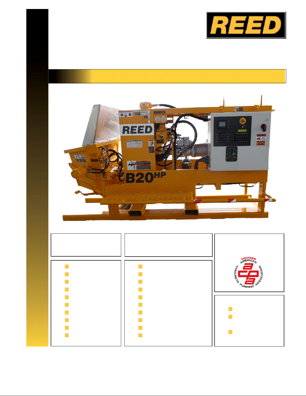
OPERATION and MAINTENANCE
B20HPC-SKE-V25 1 of 75
Chino, CA 91710
reedpumps.com
INTRODUCTION............................................................................................................. 2
WARRANTY.................................................................................................................... 3
WARRANTY CLAIM FORM....................................................................................................................... 4
SAFETY .......................................................................................................................... 5
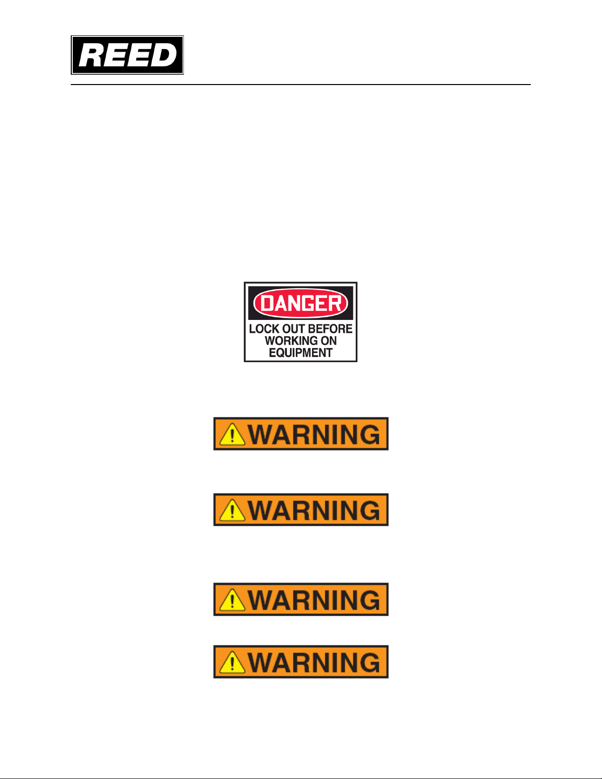
SAFETY ALERT SYMBOLS AND SIGNAL WORDS ................................................................................ 5
LOCKOUT /TAGOUT ............................................................................................................................... 6
GENERAL SAFETY GUIDELINES............................................................................................................ 6
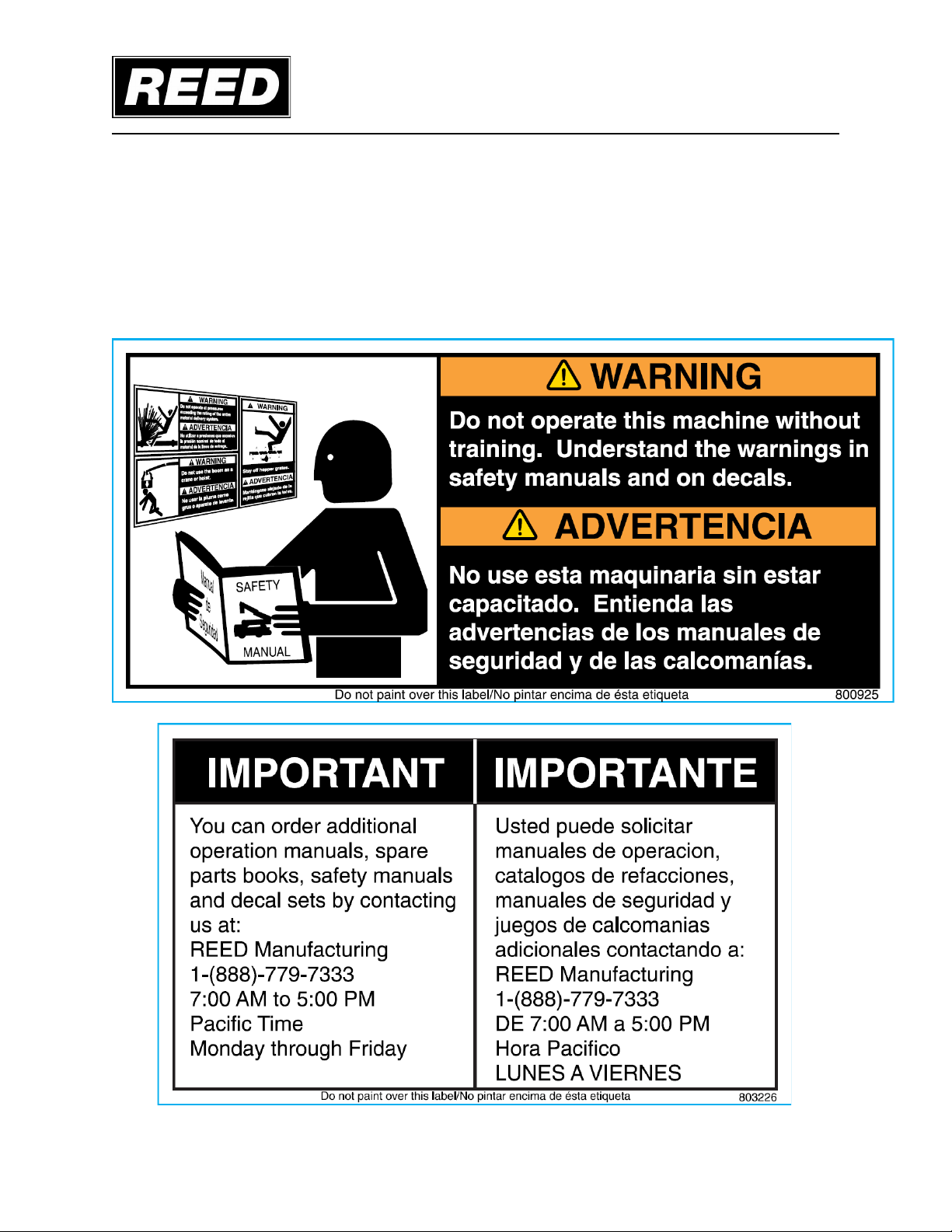
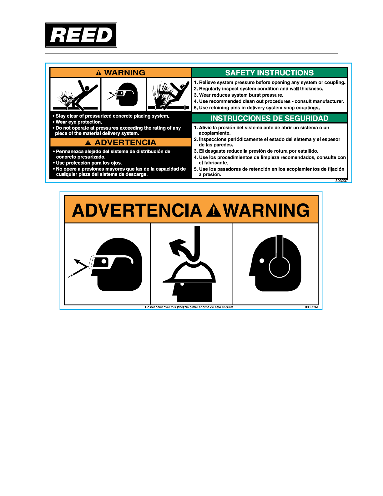
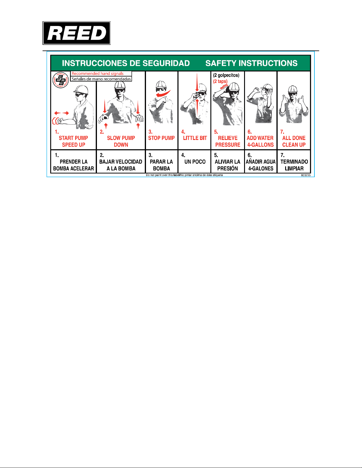
SAFETY DECALS ..................................................................................................................................... 7
OPERATION ................................................................................................................. 17
OPERATOR QUALIFICATIONS ............................................................................................................. 17
PRODUCT DESCRIPTION ..................................................................................................................... 18
HYDRAULIC SYSTEM DESCRIPTION .................................................................................................. 19
B20 SKE ELECTRIC FAMILIARIZATION................................................................................................ 26
MAIN ELECTRIC CONTROL BOX FAMILIARIZATION .......................................................................... 27
CONTROLS ............................................................................................................................................ 29
PLC MAIN CONTROLS...................................................................................................................................29
PLC MAIN CONTROLS...................................................................................................................................30
SCREEN OPERATION INSTRUCTIONS ........................................................................................... 35
REMOTE CONTROL FAMILIARIZION............................................................................................................44
OMINEX RADIO REMOTE..........................................................................................................................45
PRIMING ................................................................................................................................................. 48
PUMPING................................................................................................................................................ 49
CLEANING .............................................................................................................................................. 51
MAINTENANCE ............................................................................................................ 52
RECOMMENDED MAINTENANCE PRACTICES................................................................................... 52
GENERAL MAINTENANCE AREAS ....................................................................................................... 54
LUBRICATION ........................................................................................................................................ 56
ADDING HYDRAULIC FLUID.................................................................................................................. 62
COMPONENT REPLACEMENT ............................................................................................................. 67
S-TUBE, WEAR RING, AND WEAR PLATE....................................................................................... 67
PUMP MAINTENANCE SCHEDULEAND CHECKLISTS ...................................................................... 68
NOTES.......................................................................................................................... 75