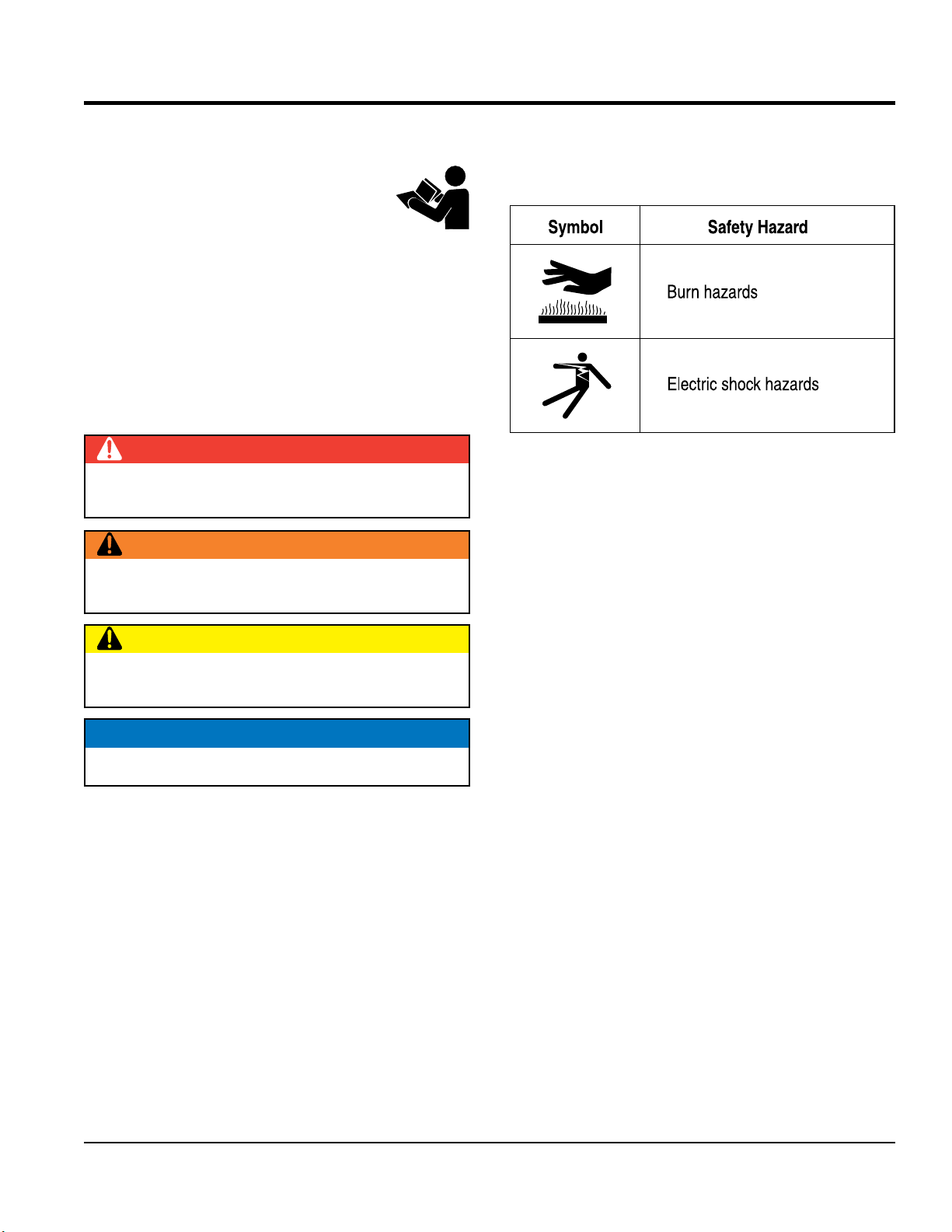
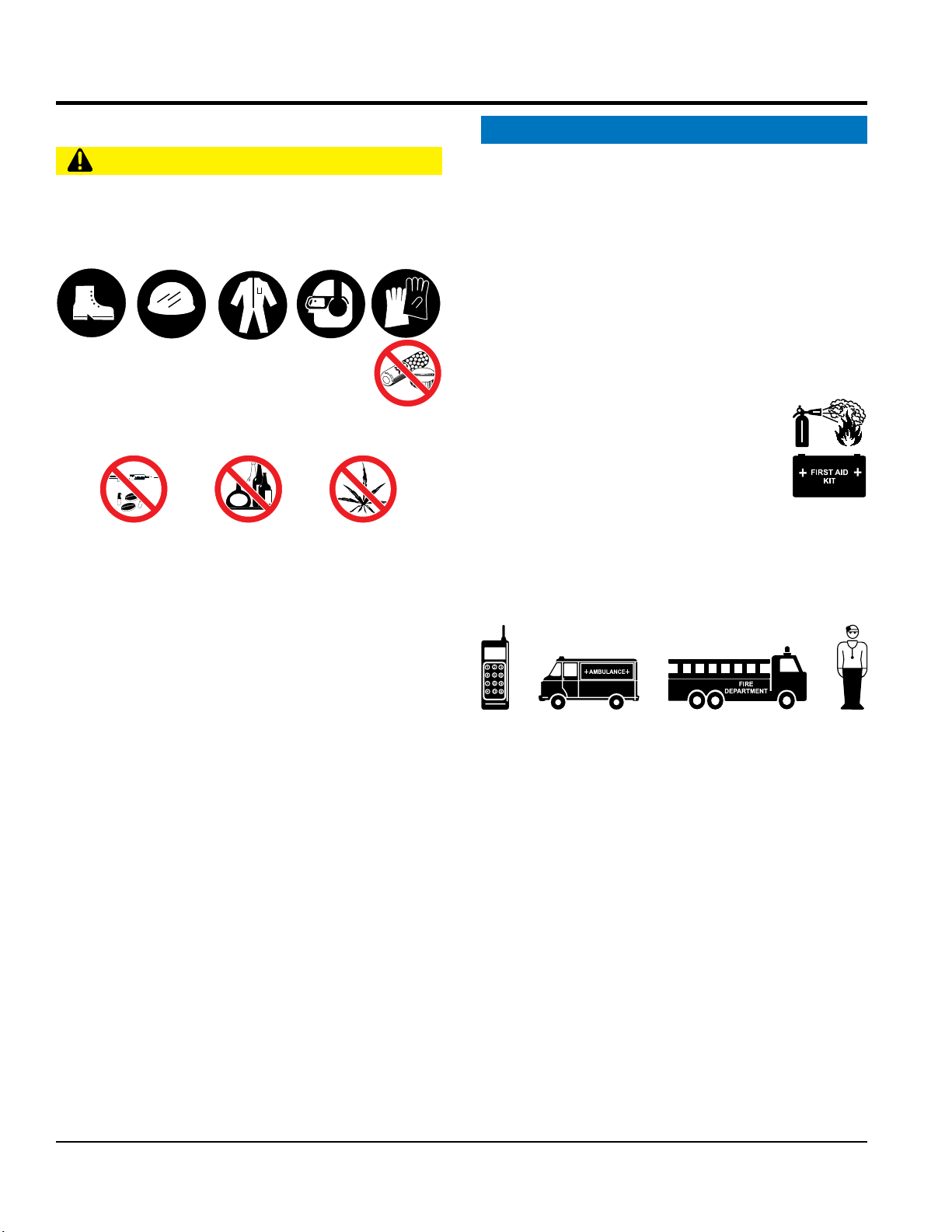
MULTIQUIP GLOBUG Series Guide

OPERATION AND PARTS MANUAL
THIS MANUAL MUST ACCOMPANY THE EQUIPMENT AT ALL TIMES.
To find the latest revision of this
publication, visit our website at:
www.multiquip.com
GLOBUG SERIES
MODELS:
GBW (Pentapod With Lamp)
Serial No. G2400001 aNd above
GBS (Offset Pole With Lamp)
Serial No. G2500001 aNd above
GBP (Lamp Only)
Serial No. G2600001 aNd above
GBHM (Hitch Mount Accessory)
GBMP (Mounting Plate)
Revision #0 (06/24/13)

NOTES


FUEL CHEMICAL WARNING
Gasoline engine exhaust and some of
its constituents are known to cause
cancer,birth defects and other
reproductive harm.

TABLE OF CONTENTS
GBW/GBS/GBP/GBHM/
GBMP Lighting System
Fuel Chemical Warning ........................................... 4
Table Of Contents.................................................... 5
Parts Ordering Procedures...................................... 6
Safety Information .............................................. 7-11
Specifications ........................................................ 12
Dimensions (GBW)................................................ 13
Dimensions (GBS)................................................. 14
Dimensions (GBP)................................................. 15
Footcandle Plot...................................................... 16
General Information............................................... 17
Components ..................................................... 18-19
Setup ................................................................ 20-24
Operation.......................................................... 25-27
Maintenance..................................................... 28-33
Wiring Diagram...................................................... 34
Explanation Of Code In Remarks Column............. 36
Suggested Spare Parts ......................................... 37
Component Drawings
Nameplates And Decals (GBW)....................... 38-39
Nameplates And Decals (GBS)........................ 40-41
Balloon and Lamp Assy (GBW/GBS) ............... 42-45
Mast Assy (GBW)............................................. 46-47
Pentapod Assy (GBW)...................................... 48-49
Pole Assy (GBS)............................................... 50-51
Hitch Mount Assy (GBHM) ............................... 52-53
Plate Mount Assy (GBMP)................................ 54-55
Terms and Conditions of Sale — Parts ................. 56
NOTICE
Specifications and part numbers are subject to change
without notice.

PARTS ORDERING PROCEDURES
www.multiquip.com
Ordering parts has never been easier!
Choose from three easy options:
When ordering parts, please supply:
❒
❒
❒
❒
❒
❒
❒
✓ UPS/Fed Ex ✓DHL
■Priority One ✓Tr u ck
■Ground
■Next Day
■Second/Third Day
If you have an MQ Account, to obtain a Username
and Password, E-mail us at:
To obtain an MQ Account, contact your
District Sales Manager for more information.
Order parts on-line using Multiquip’s SmartEquip website!
■View Parts Diagrams
■Order Parts
■Print Specification Information
Note: Discounts Are Subject To Change
Goto www.multiquip.com and click on
Order Parts to log in and save!
Use the internet and qualify for a
on Standard orders for all orders which include
complete part numbers.*
All customers are welcome to order parts via Fax.
1-800-6-PARTS-7 (800-672-7877)
Fax your order in and qualify for a
on Standard orders for all orders which include
complete part numbers.*
1-800-427-1244
International Customers should contact
their local Multiquip Representatives for
Parts Ordering information.
Contact your local Multiquip Dealer for
parts or call 800-427-1244 for help in
locating a dealer near you.
Note: Discounts Are Subject To Change
Effective:
January 1st
, 2006
NOTICE
All orders are treated as Standard Orders and will
ship the same day if received prior to 3PM PST.

SAFETY INFORMATION
Do not operate or service the equipment before reading
the entire manual. Safety precautions should be followed
at all times when operating this equipment.
Failure to read and understand the safety
messages and operating instructions could
result in injury to yourself and others.
The four safety messages shown below will inform you
about potential hazards that could injure you or others.The
safety messages specifically address the level of exposure
to the operator and are preceded by one of four words:
or
Indicates a hazardous situation which, if not avoided,
WiLL result in or
Indicates a hazardous situation which, if not avoided,
result in or
CAutiON
Indicates a hazardous situation which, if not avoided,
result in or
NOTICE
Addresses practices not related to personal injury.
Potential hazards associated with the operation of this
equipment will be referenced with hazard symbols which
may appear throughout this manual in conjunction with
safety messages.

SAFETY INFORMATION
CAutiON
operate this equipment without proper protective
clothing, shatterproof glasses, respiratory protection,
hearing protection, steel-toed boots and other protective
devices required by the job or city and state regulations.
operate this equipment when not
feeling well due to fatigue, illness or when
under medication.
operate this equipment under the influence of
drugs or alcohol.
ALWAYS check the equipment for loosened threads or
bolts before starting.
use the equipment for any purpose other than
its intended purposes or applications.
NOTICE
This equipment should only be operated by trained and
qualified personnel 18 years of age and older.
Whenever necessary, replace nameplate, operation and
safety decals when they become difficult read.
Manufacturer does not assume responsibility for any
accident due to equipment modifications. Unauthorized
equipment modification will void all warranties.
use accessories or attachments that are not
recommended by Multiquip for this equipment. Damage
to the equipment and/or injury to user may result.
ALWAYS know the location of the nearest
ALWAYS know the location of the nearest phone or
Also, know the phone numbers
of the nearest and
This information will be invaluable in the case of an
emergency.

SAFETY INFORMATION
disconnect any
These devices are intended for operator safety.
Disconnection of these devices can cause
Disconnection of any of
these devices will void all warranties.
CAutiON
attempt service on a running machine.
NOTICE
To prevent the lighting system from overturning,
use in winds that exceed 22 mph (10 m/s).
The lighting system should only be used in temperatures
between 23° to 104°F (-5° to 40° C). Failure to comply
with these operating parameters could cause the lamp
to malfunction and shorten the ballast life.
ALWAYS keep the lighting system in proper running
condition.
Fix damage to lighting system and replace any broken
parts immediately.
ALWAYS store equipment properly when it is not being
used. Equipment should be stored in a clean, dry location
out of the reach of children and unauthorized personnel.
attempt to replace lamp with the power on.
Always unplug the power cord from the generator or
power source when changing the lamp.
ALWAYS allow a sufficient amount of time for the lamp to
before changing. The possibility exists of severe burns.
CAutiON
use force when installing the lamp.Excessive force
could cause the lamp to break, causing bodily harm.
NOTICE
leave any grease or oil residue on lamp surface
when replacing or removing lamp. This can create hot
spots, reducing the service life of the lamp.
ALWAYS make sure lamp surface is clean and dry.
ALWAYS
replace with MQ recommended type lamp. See
parts section of this manual.
If applicable, ALWAYS
make sure the lamp guard is
installed correctly. deform the lamp guard.
unplug the lamp’s AC power cable during
operation.
ALWAYS have a
to install and
remove lamp or replace any damaged fixture wiring.

SAFETY INFORMATION
To prevent serious burns, touch
or unzip the balloon envelope when the
lamp is on.
CAutiON
ALWAYS keep the balloon away from sharp objects and
excessive amounts of heat.
NOTICE
To prevent balloon deformation, use lighting
system in strong winds.
place the balloon inside its protective cover
until the lamp has had a sufficient amount of time to cool
down. This will prevent the balloon’s nylon cover from
being burned (touching the lamp surface).
ALWAYS place the balloon inside its protective cover
after each use. This will prolong the life of the balloon
material, keeping it protected from harsh environmental
elements.
Replace balloon immediately if damaged. A damaged
balloon will not inflate properly, and may become more
damaged by touching the hot lamp surface.
use excessive force when zipping and unzipping
the balloon. Be gentle with the zipper mechanism. If the
zipper is broken, the balloon will become unusable.
If using a generator to power lighting system,
refer to applicable generator manual safety
information section.
Lighting system is equipped with a ground pin on the
power plug. For your protection, ALWAYS
complete the
grounding path.
insert the AC power plug into a
2-prong receptacle to operate lighting system.
When applying power to the lighting system,
ALWAYS
connect the AC power plug to a 3-prong receptacle that
is grounded. The possibility exists of
if the lighting system is
not grounded.
operate lighting system or
handle any electrical equipment while
standing in water, while barefoot, while
hands are wet or in the rain.A dangerous
could occur, causing
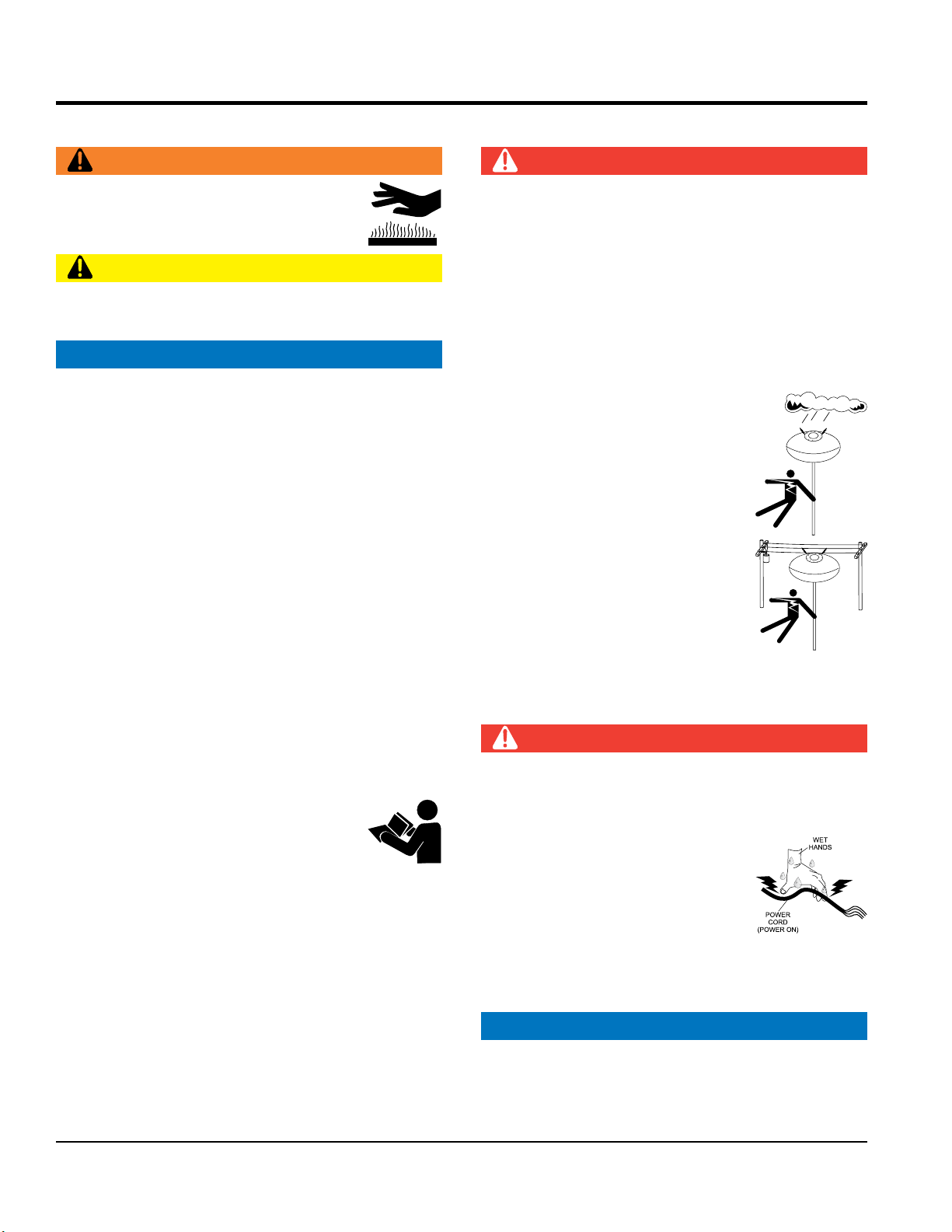
ALWAYS make sure the area above
the lighting system is open and clear
of overhead power lines and other
obstructions. Contact with overhead
power lines or other obstructions could
result in equipment damage,
let power cords or cables
use or
cables or cords. Inspect
for cuts in the insulation
grab or touch a live power
cord or cable with wet hands. The
possibility exists of
Make sure power cables are securely connected.
Incorrect connections may cause
and
damage to the lighting system.
NOTICE
ALWAYS
make certain that proper power or extension
cord has been selected for the job. See Cable Selection
Chart in this manual.

SAFETY INFORMATION
If lighting system is equipped with a transport lifting hook,
refer to the following safety information.
CAutiON
Before lifting, make sure that lighting system parts are
not damaged and screws are not loosened or lost.
ALWAYS make sure crane or lifting device has been
properly secured to lifting hook of the equipment.
lift the equipment while lighting system is
running.
Make sure the mast is completely lowered before lifting
the lighting system.
Use adequate lifting cable (wire or rope) of sufficient
strength.
Use one point suspension hook and lift straight upwards.
Never allow any person or animal to stand underneath the
equipment while lifting.
lift machine to unnecessary heights.
If lighting system is not equipped with a transport lifting
hook and the mast is removable, refer to the following
safety information.
Before lifting, make sure that the mast and lamp are
removed as described in the manual.
The cart can be safely lifted by two persons to the
transport vehicle.
NOTICE
When transporting the lighting system, if applicable,
always place in
and place mast in its
carrying case.
ALWAYS
remove balloon/lamp assembly from the mast
when transporting lighting system. This will prevent
damage to the bulb due to vibration.
leave the balloon/lamp exposed during transport.
Exposure to excess wind or rain could damage the
balloon’s nylon cover.
ALWAYS
place balloon inside its protective cover during
transport. Be sure the cover is secured tightly around the
balloon/lamp assembly.

SPECIFICATIONS
Model GBW/GBS/GBP
Input Voltage 90-130, 170-240 VAC
Max. Current 9.3 A @ 120 V
Frequency 50-60 Hz Single-Phase
Appropriate Generator 1200 Watts
Lamp Type 1,000 Watt Metal Halide
Total Luminous Flux 99,750 lm
Standard Balloon Diameter 47.2 in (1200 mm)
Light Coverage (360°) 150 ft (45.7 meters)
Lamp Surface Temperature (Longitudinal) 476.6° F (247° C) max
Lamp Surface Temperature (Transversal) 417.2° F (214° C) max
Dimensions (L x W x H)
Storage (Lamp)
7.9 x 8.7 x 27.0 in.
(200 x 220 x 685 mm)
BALLOON
Balloon Dimensions (L x W x H) 47.2 x 47.2 x 25.6 in.
(1200 x 1200 x 650 mm)
Balloon Material Polyester
Balloon Heat-Resisting Temperature 320-356° F (160-180° C)
Internal Balloon Temperature 126° F (52° C)
Balloon Water Resistance 1500 mm H
2
O
Fan Motor Voltage 24 VDC
Fan Motor Current 1.2 A
Fan Motor Pressure 0.324 kPA (0.047 psi)
Outriggers 5
Mast - Number of Stages 3 (air shock absorbers)
GBW Dimensions (L x W x H)
Upper Working Position
54.0 x 56.7 x 84.4 to 136.8 in
(1,370 x 1,440 x 2,145 to 3,475 mm)
Dimensions (L x W x H)
Storage (Pentapod)
8.7 x 8.7 x 40.0 in
(220 x 220 x 1015 mm)
Weight 57.6 lb (21.5 kg)
Mast - Number of Stages 2 stages (offset and straight pole)
Dimensions (L x W x H)
Upper Working Position
47.2 x 50.6 x 78.0 in
(1200 x 1285 x 1980 mm)
Dimensions (L x W x H)
Storage
Straight Pole: 39.4 in (1,000 mm)
Offset Pole: 26.9 x 16.7 x 2 in (683 x 425 x 52 mm)
Weight 44.2 lb (16.5 kg)

DIMENSIONS (GBW)
A
D
B
E
C
A Total Max. Height (with Standard Balloon) 136.8 (3,475)
B Standard Balloon Height 25.6 (650)
C Mast Height (without Balloon) 111.0 (2,820)
D Standard Balloon Diameter 47.2 (1,200)
E Mast Height (Stowed) 40.0 (1,015)
Figure 1. GBW Dimensions

DIMENSIONS (GBS)
D
A
H
I
J
G
BE
F
BALLOON
ASSEMBLY
STRAIGHT POLE
OFFSET POLE
C
Figure 2. GBS Dimensions
A 50.6 (1,285)
B 47.2 (1,200)
C 25.6 (650)
D 78.0 (1980)
E 26.9 (683)
F 16.7 (425)
G 39.4 (1,000)
H 8.7 (220)
I 7.9 (200)
J 27.0 (685)

DIMENSIONS (GBP)
A
B
Figure 3. GBP Dimensions
A 47.2 (1,200)
B 25.6 (650)

FOOTCANDLE PLOT
10
5
2
1
.5
.25
VALUES LISTED AS FOOTCANDLES SCALE: 1GRID=50FT. (15.24 METERS)
Figure 4. Illumination Range

GENERAL INFORMATION
The Multiquip GloBug GBW, GBS, GBP are general-
purpose, portable, glare-free lighting systems intended
for emergency and remote lighting needs. It is universally
adaptable to all AC power supplies and accepts 50/60 Hz,
100-240 V.
The GBP (also included with the GBW and GBS) provides
360° glarefree illumination.The balloon is self-inflating and
easy to install and inflate in less than 20 seconds. It uses a
single 1,000 watt lamp with pure white light for maximum
illumination with a light coverage of up to 150 feet. The
balloon is self-inflating and easy to install and inflate in
less than 20 seconds.
115V 25 Ft. 50 Ft. 100 Ft. 150 Ft. 200 Ft. 250 Ft. 300 Ft. 400 Ft. 500 Ft.
230V 50 Ft. 100 Ft. 200 Ft. 300 Ft. 400 Ft. 500 Ft. 600 Ft. 800 Ft. 1000 Ft.
0 - 2 18 18 18 16 16 14 14 12 12
2 - 3 18 18 16 14 14 12 12 10 10
3 - 4 18 18 16 14 12 12 10 10 8
4 - 5 18 18 14 12 12 10 10 8 8
5 - 6 18 16 14 12 10 10 8 8 6
6 - 8 18 16 12 10 10 8 6 6 6
8 - 10 18 14 12 10 8 8 6 6 4
10 - 12 16 14 10 8 8 6 6 4 4
12 - 14 16 12 10 8 6 6 6 4 2
14 - 16 16 12 10 8 6 6 4 4 2
16 - 18 14 12 8 8 6 4 4 2 2
18 - 20 14 12 8 6 6 4 4 2 2
The GBW has a three-stage mast that extends to a height
of up to 13 feet and 2 inches.The GBW has five outriggers
(pentapod) for great stabilization.
The GBS is designed to be attached to an external piece of
equipment such as a paver.The system is easy to assemble
and includes poles and mounting brackets.
The GBHM Hitch Mount can be used to attach a GBP to
a hitch on a truck.
The GBMP Plate Mount can be used to attach a GBP to
a trailer.
If an extension cord is necessary to connect to a power
source, refer to Table 5 to select the proper length.

COMPONENTS
1
2
3
4
11
12
13
15
16
17
14
23
24 25
5
7
9
18
10
8
6
GBW/GBWE
GBWE*/GBHM/
GBMP ONLY GBHM GBMP
GBP
*Extension pole for GBWE is 35 inches long, aluminum.
26
19
21
22
5
20
GBS
Figure 5. GBW/GBS/GBP Components

COMPONENTS
Figure 5 shows the location of the controls and components
for the GBW Lighting System.The functions of each control
is described below:
1. — Stores balloon when GBW is not in
use. Allow a sufficient amount of time for the lamp to
cool down before storing balloon. Possibility exists of
balloon getting burned.
2. — Made of heat resistant polyester, with a
diameter of 47.2 inches (1,200 mm). Balloon is self-
inflating and inflates in less than 20 seconds.
3. — Used to easily attach optional message strip
to the balloon.
4. — Used to hold the balloon together when
storing inside the cover.
5. — Connects to the AC power source
(generator).
6. — Supports and holds up the GBW.
7. — To secure the pentapod, place the lock in the
upper or lower position.
8. — Supports the mast against the pentapod.
9. — This mast is comprised of three separate
stages. The mast can be raised in excess of 8 feet
(without balloon). When raising the mast, always be
on the lookout for overhead obstructions.
10. — Loosen to raise mast and tighten to keep
the mast in place when raised to the desired height.
11. — A 12 x 43 inch
message strip (GBBALD1) may be attached to
the balloon. The message strip can be purchased
separately.
12. — Zips up balloon to completely close it when
lamp is in place.
13. — Holds lamp in place. Lamp is screwed
into socket.
14. — Used to tighten mast when
attached to the lamp/balloon assembly.
15. — Inflates the balloon as soon
as power is applied.
16. — 1000 watt metal halide bulb with pure white
light for maximum illumination.
17. — Protects the lamp from being hit by
objects and the balloon from touching the lamp.
18. — Use this case to store the pentapod
when transporting or when not in use.
19. — Supports lamp assembly when attached
to the straight pole.
20. — Secures the offset pole to the straight pole
when tightened.
21. — Used in conjunction with the offset
pole to support the lamp assembly.
22. — Used to attach the straight pole to an
external support. These clamps must be tightened
securely to prevent the light assembly from falling off.
23. — Extends mast height by 35 inches.
For GBHM and GBMP, 2 poles are included to support
the desired balloon assembly.
24. — Used to attach balloon
assembly to a hitch on a truck or similar vehicle.
25. — Used to attach balloon
assembly to a trailer or similar vehicle.
26. — Attaches directly to a trailer to hold plate
mount assembly.

SETUP
GBW Setup
1. Set the GBW on a firm level surface where there is
enough space around the pentapod for the outriggers
to be deployed.
2. Remove the pentapod from the carrying case. The
pentapod outriggers are secured together with a strap.
See Figure 6. Squeeze both tabs on the buckle to
unlock strap and release pentapod outriggers.
Figure 6. Releasing Pentapod Buckle
3. Lift mast up and deploy the pentapod as shown in
Figure 7.
Figure 7. Deploying the Pentapod
4. With pentapod fully deployed, hook the latch to lock
the pentapod in place. The latch can be hooked in the
SQUEEZE
BUCKLE
PENTAPOD
OUTRIGGER
STRAP
DEPLOY
PENTAPOD
upper or lower position. Placing the lock in the upper
position will provide 1 foot (305 mm) more height. See
Figure 8.
Figure 8. Securing the Pentapod
5. If desired, attach extension pole to the top of the mast
as shown in Figure 9.
Figure 9. Attaching Extension Pole
6. To improve stability and prevent tipping of the lighting
system, place sand bags on the outriggers or similar
weight on the weight hook as shown in Figure 10.
Figure 10. Sand Bags and Weight
UPPER
POSITION
LATCH
LOWER
POSITION
EXTENSION
POLE
BOLT
SANDBAG
WEIGHT HOOK
WEIGHT
Other manuals for GLOBUG Series
2
This manual suits for next models
6
Table of contents
Other MULTIQUIP Industrial Equipment manuals