THERMA Trapzilla TZ-1826 Installation and operating instructions

A THERMACO® Technology
For additional information on Trapzilla or other Thermaco products,
please visit www.trapzilla.com or call at 1-800-633-4204.
Copyright ©2018 Trapzilla®Thermaco, Inc. • P.O.Box 2548 • Asheboro, NC 27204
Toll Free: (800) 633-4204 • Phone: (336) 629-4651 • Fax: (336) 626-5739
Installation & Maintenance Instructions
For Trapzilla®TZ-1826
Part# MNL-TZ-1826
AEF
*Please consult Thermaco, Inc. for specic models tested,
certied and/or listed by these organizations.
1
1
2
2
3
3
4
4
A A
B B
C C
D D
THIS DRAWING CONTAINS PROPRIETARY AND PATENTED MATERIAL. THIS DRAWING MAY NOT BE REPRODUCED IN WHOLE OR PART WITHOUT
WRITTEN CONSENT FROM THERMACO, INC. POSSESSION OF THIS DRAWING DOES NOT CONSTITUTE THE RIGHT TO MANUFACTURE.
POSSESSION OF THIS DRAWING DOES CONSTITUTE AN IMPLIED NONDISCLOSURE AGREEMENT BETWEEN THERMACO, INC. AND THE HOLDER OF
THIS DRAWING. DO NOT DESTROY THIS DRAWING, IT IS THE SOLE PROPERTY OF THERMACO, INC. AND MUST BE RETURNED UPON REQUEST.
MATERIAL (UNLESS NOTED)
FINISH (UNLESS NOTED)
646 GREENSBORO STREET
PO BOX 2548, ASHEBORO, NC 27203
VOICE 336-629-4651 FAX 336-626-5739 Decimals
.XX +/- .03
.XXX +/- .015
Unless otherwise specified
Dimensions are in inches
Tolerances
Angular
+/- 1°
CHECKED SIZE REV. NO. DWG NO.
PART NO. C
SCALE RELEASE DATE SHEET OF
ENGINEERING
DRAWN DATE
THIRD ANG LE PRO JECTION
®
Conforms to ASME Standard
ASME A112.14.3-2000
Please consult Thermaco, Inc. for specic models tested,
certied and/or listed by these organizations.
®
©2018 Thermaco, Inc. All rights reserved • Patented/Patents Pending • Specications subject to change without notice
Thermaco, Inc. • 646 Greensboro St. • Asheboro, N. C. 27204-2548 • (336) 629-4651 MNL-TZ-1826 3
A THERMACO® Technology
Trapzilla®Grease Interceptor
Installation and Operations Manual
TZ-1826 Models
AEF
MNL-TZ-1826 2
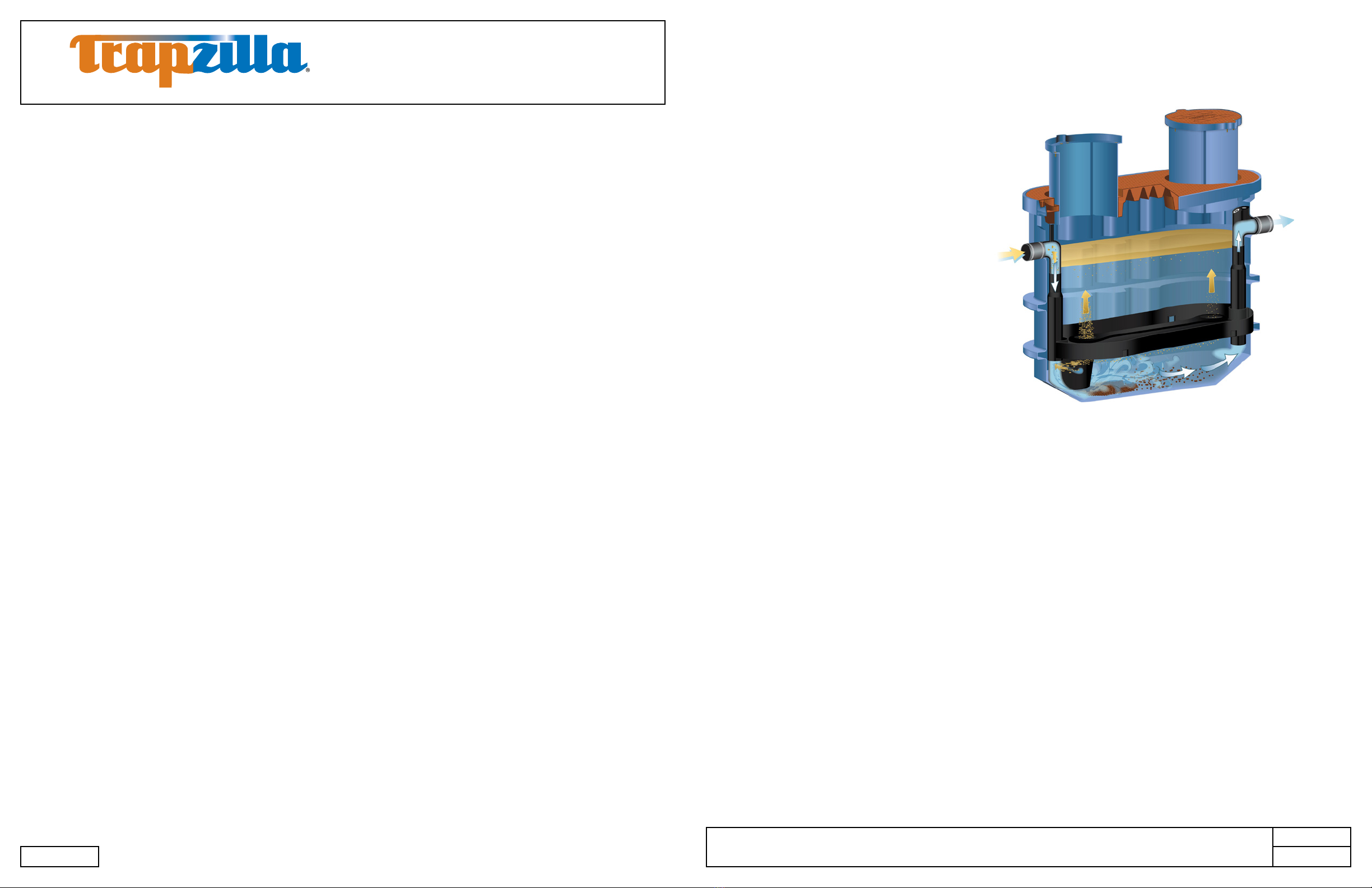
1. System Overview
The Thermaco, Inc. Trapzilla®Supercapacity
Grease Interceptor collects free-floating
grease & oils contained in kitchen drain water
ows. As most food service facility managers
already know, grease buildup inside a
building’s grease containment system is a
major cause of problems due to exterior drain
line blockages. These problems jeopardize
normal operations as well as create health
and safety hazards within the facility itself.
The proper installation of a Trapzilla®
Supercapacity Grease Interceptor can
reduce or eliminate grease problems and
costly sewer surcharges and nes through
efcient separation and retention of free-
oating grease & oils.
The Trapzilla offers patented at separation
curve technology. This means that the unit does not lose grease separation efciency as it lls with
retained grease. Thus, the Trapzilla stores large quantities of grease without losing efciency. The
unique compact design of the Trapzilla allows for installation into most facilities. Options are available
that enable a Trapzilla unit to be installed on the oor, suspended from the ceiling or in-ground outside
the facility.
Trapzilla units are designed to treat high ows of kitchen drainwater with large grease storage capacity
within a small footprint unit. These units are easy to maneuver into position and just as easy to plumb.
Hydromechanical grease interceptors, automatic recovery units, grease removal devices and other
similar plumbing devices receiving kitchen ows from sinks, oor drains, woks and other food bearing
sources may generate odors. There are many factors inuencing odor evolution and dissemination.
These include room ventilation, kitchen menu, ambient temperatures, ware washing practices, grease/oil
input, daily input uid volume, sanitizers, installation plumbing design and product maintenance/upkeep.
Odors are usually prevented by good area ventilation, frequent uid inputs, good product maintenance
practices and proper product installation. Additional steps, including aeration, chlorination, pH control,
improved area ventilation and additional maintenance may be needed at some sites.
*Devices formerly referred to as grease traps are now called hydromechanical grease interceptors.
Contents
1. System Overview.................................................................................................................................... 3
2. Models and Options................................................................................................................................ 4
2.1 Models ........................................................................................................................................... 4
2.2 Options .......................................................................................................................................... 5
3. Plumbing Installation .............................................................................................................................. 6
3.1 Plumbing Considerations Prior to Installation................................................................................ 6
3.1.1 Locating the Unit................................................................................................................... 6
3.1.2 Inlet/Outlet Piping ................................................................................................................. 6
3.1.3 Flow Controls........................................................................................................................ 6
3.1.4 Venting the Outlet ................................................................................................................. 6
3.1.5 High Head Height Applications Over Six (6) Feet (1.95 m) .................................................. 6
3.2 Vessel Vent Connection.................................................................................................................. 7
3.3 Plumbing Congurations ................................................................................................................ 8
3.3.1 One TZ-1826 ......................................................................................................................... 8
3.3.2 Installing Multiple Trapzilla Units in Parallel........................................................................... 9
3.3.3 Installing Multiple Trapzilla Units in Series............................................................................. 10
4. Above-Ground Installation ...................................................................................................................... 11
4.1 Components for Above-Ground Installations.................................................................................. 11
4.2 Instructions for Assembling and Attaching External Brace ............................................................. 12
4.3 Instructions for Installing Multiple Trapzilla Units Above-Ground.................................................... 12
4.3.1 Installing TZ-1826-SSA with TSS-95-SSA in Series .............................................................. 12
4.3.2 Construction of Riser for TSS-95-SSA installation in series with TZ-1826-SSA.................... 13
4.3.3 Installing Multiple TZ-1826-SSA in Series ............................................................................. 13
4.3.4 Installation of Pipe Hangers with Above-Ground Units .......................................................... 14
5. In-Ground Installation Instructions.......................................................................................................... 15
5.1 Single TZ-1826 Installed In-Ground ............................................................................................... 15
5.2 TZ-1826 with Optional ECA-TZ-29 Extension Collars .................................................................... 16
5.3 Concrete Specications for In-Ground Installation ......................................................................... 17
5.4 Concrete Calculations for TZ-1826 Models/Components* ............................................................. 17
5.5 Trimming and Setting the ECA-TZ-18 Single-Piece Extension Collar ............................................ 18
6. Unit Maintenance.................................................................................................................................... 20
6.1 Measuring Grease/Solids Levels.................................................................................................... 20
6.2 Pumping/Servicing Unit .................................................................................................................. 21
7. Limited Warranty and Remedy ............................................................................................................... 22

©2018 Thermaco, Inc. All rights reserved • Patented/Patents Pending • Specications subject to change without notice
Thermaco, Inc. • 646 Greensboro St. • Asheboro, N. C. 27204-2548 • (336) 629-4651 MNL-TZ-1826 5
A THERMACO® Technology
Trapzilla®Grease Interceptor
Installation and Operations Manual
TZ-1826 Models
AEF
MNL-TZ-1826 4
1
1
2
2
3
3
4
4
A A
B B
C C
D D
THIS DRAWING CONTAINS PROPRIETARY AND PATENTED MATERIAL. THIS DRAWING MAY NOT BE REPRODUCED IN WHOLE OR PART WITHOUT
WRITTEN CONSENT FROM THERMACO, INC. POSSESSION OF THIS DRAWING DOES NOT CONSTITUTE THE RIGHT TO MANUFACTURE.
POSSESSION OF THIS DRAWING DOES CONSTITUTE AN IMPLIED NONDISCLOSURE AGREEMENT BETWEEN THERMACO, INC. AND THE HOLDER OF
THIS DRAWING. DO NOT DESTROY THIS DRAWING, IT IS THE SOLE PROPERTY OF THERMACO, INC. AND MUST BE RETURNED UPON REQUEST.
MATERIAL (UNLESS NOTED)
FINISH (UNLESS NOTED)
646 GREENSBORO STREET
PO BOX 2548, ASHEBORO, NC 27203
VOICE 336-629-4651 FAX 336-626-5739 Decimals
.XX +/- .03
.XXX +/- .015
Unless otherwise specified
Dimensions are in inches
Tolerances
Angular
+/- 1°
CHECKED SIZE REV. NO. DWG NO.
PART NO. C
SCALE RELEASE DATE SHEET OF
ENGINEERING
DRAWN DATE
THIRD ANGLE PROJEC TION
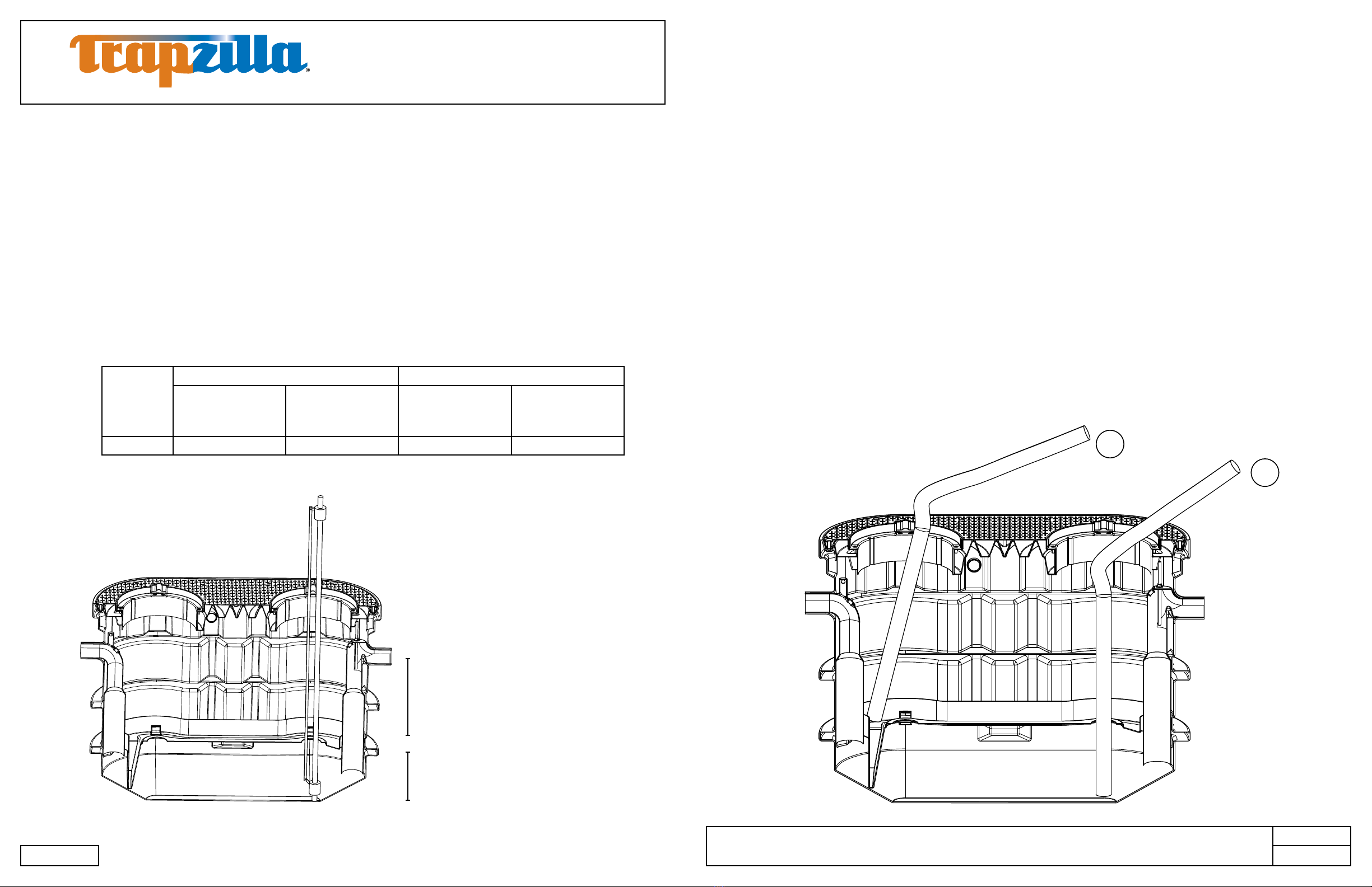
TZ-1826
1,826 pounds of grease storage, PDI and ASME rated
at 100 gpm. Equipped with 4” inlet/outlet, 2” vessel vent
connection, and 4” Low-Head Flow Control Accessory to
limit ow to 100 gpm.
Comes with: Extension Collar Adapter Lid Assembly with
two 18” tall extension collars and two 22” diameter lids.
1
1
2
2
3
3
4
4
A A
B B
C C
D D
THIS DRAWING CONTAINS PROPRIETARY AND PATENTED MATERIAL. THIS DRAWING MAY NOT BE REPRODUCED IN WHOLE OR PART WITHOUT
WRITTEN CONSENT FROM THERMACO, INC. POSSESSION OF THIS DRAWING DOES NOT CONSTITUTE THE RIGHT TO MANUFACTURE.
POSSESSION OF THIS DRAWING DOES CONSTITUTE AN IMPLIED NONDISCLOSURE AGREEMENT BETWEEN THERMACO, INC. AND THE HOLDER OF
THIS DRAWING. DO NOT DESTROY THIS DRAWING, IT IS THE SOLE PROPERTY OF THERMACO, INC. AND MUST BE RETURNED UPON REQUEST.
MATERIAL (UNLESS NOTED)
FINISH (UNLESS NOTED)
646 GREENSBORO STREET
PO BOX 2548, ASHEBORO, NC 27203
VOICE 336-629-4651 FAX 336-626-5739
Decimals
.XX +/- .03
.XXX +/- .015
Unless otherwise specified
Dimensions are in inches
Tolerances
Angular
+/- 1°
CHECKED SIZE REV. NO. DWG NO.
PART NO.
C
SCALE RELEASE DATE SHEET OF
ENGINEERING
DRAWN DATE
THIRD ANGLE PROJECT ION
TZ-1826-SSA
1,826 pounds of grease storage, PDI and ASME rated
at 100 gpm. Equipped with 4” inlet/outlet, 2” vessel vent
connection, and 4” Low-Head Flow Control Accessory to
limit ow to 100 gpm.
Comes with: Extension Collar Adapter Lid Assembly with
two 18” tall extension collars, two 22” diameter lids,external
brace (not pictured) and SSA-1826 Support Stand.
*Models available with 6” Inlet/Outlet, add sufx -6 to model.
2. Models and Options
Thermaco offers different models and options specically designed to assist the owner/installer meet
site conditions while complying with local pretreatment and plumbing code.
2.1 Models
2.2 Options (Some options must be purchased separately)
FTCA-22
Optional 22” diameter cover available for
In-Ground installations. Provides a non-slip,
diamond patterned aluminum replacement for
the standard STC-22 cover. Each TZ-1826
would require two (2) FTCA-22 covers.
SSA-1826
Support Stand for TZ-1826 for Above-Ground
Installations. Must be fully supported, not to
be installed over grates.
*Included with TZ-1826-SSA Models
ECA-TZ-29
(purchase separately)
Optional, eld-modiable extension
collars available to provide
additional depth for existing kitchen
drainage piping.
• TZ-1826-ECA Models ship with
two (2) built-in 0-18” extension
collars.
• ECA-TZ-29 adds 0-29” depth
to -ECA model.
• Contact Thermaco before
installing any Trapzilla more
than 60” below grade from
center of outlet pipe or in
location where water table will
ever rise above bottom of unit.
1
1
2
2
3
3
4
4
A A
B B
C C
D D
THIS DRAWING CONTAINS PROPRIETARY AND PATENTED MATERIAL. THIS DRAWING MAY NOT BE REPRODUCED IN WHOLE OR PART WITHOUT
WRITTEN CONSENT FROM THERMACO, INC. POSSESSION OF THIS DRAWING DOES NOT CONSTITUTE THE RIGHT TO MANUFACTURE.
POSSESSION OF THIS DRAWING DOES CONSTITUTE AN IMPLIED NONDISCLOSURE AGREEMENT BETWEEN THERMACO, INC. AND THE HOLDER OF
THIS DRAWING. DO NOT DESTROY THIS DRAWING, IT IS THE SOLE PROPERTY OF THERMACO, INC. AND MUST BE RETURNED UPON REQUEST.
MATERIAL (UNLESS NOTED)
FINISH (UNLESS NOTED)
646 GREENSBORO STREET
PO BOX 2548, ASHEBORO, NC 27203
VOICE 336-629-4651 FAX 336-626-5739 Decimals
.XX +/- .03
.XXX +/- .015
Unless otherwise specified
Dimensions are in inches
Tolerances
Angular
+/- 1°
CHECKED SIZE REV. NO. DWG NO.
PART NO. C
SCALE RELEASE DATE SHEET OF
ENGINEERING
DRAWN DATE
THIRD ANGLE PROJE CTION
0-18” Built-In
Extension ECA-TZ-29
1
1
2
2
3
3
4
4
A A
B B
C C
D D
THIS DRAWING CONTAINS PROPRIETARY AND PATENTED MATERIAL. THIS DRAWING MAY NOT BE REPRODUCED IN WHOLE OR PART WITHOUT
WRITTEN CONSENT FROM THERMACO, INC. POSSESSION OF THIS DRAWING DOES NOT CONSTITUTE THE RIGHT TO MANUFACTURE.
POSSESSION OF THIS DRAWING DOES CONSTITUTE AN IMPLIED NONDISCLOSURE AGREEMENT BETWEEN THERMACO, INC. AND THE HOLDER OF
THIS DRAWING. DO NOT DESTROY THIS DRAWING, IT IS THE SOLE PROPERTY OF THERMACO, INC. AND MUST BE RETURNED UPON REQUEST.
MATERIAL (UNLESS NOTED)
FINISH (UNLESS NOTED)
646 GREENSBORO STREET
PO BOX 2548, ASHEBORO, NC 27203
VOICE 336-629-4651 FAX 336-626-5739 Decimals
.XX +/- .03
.XXX +/- .015
Unless otherwise specified
Dimensions are in inches
Tolerances
Angular
+/- 1°
CHECKED SIZE REV. NO. DWG NO .
PART NO. C
SCALE RELEASE DATE SHEET OF
ENGINEERING
DRAWN DATE
THIRD ANGLE PROJE CTION
21.13 in
[53.7 cm]
R10.56 in
[26.8 cm]
R11.56 in
[29.4 cm]
1.50 in
[3.8 cm]
23.10 in
[58.7 cm]
ANGLE STIFFENERS
Bottom View
Top View
Side View
DIAMOND PLATE SURFACE
1
1
2
2
3
3
4
4
A A
B B
C C
D D
THIS DRAWING CONTAINS PROPRIETARY AND PATENTED MATERIAL. THIS DRAWING MAY NOT BE REPRODUCED IN WHOLE OR PART WITHOUT
WRITTEN CONSENT FROM THERMACO, INC. POSSESSION OF THIS DRAWING DOES NOT CONSTITUTE THE RIGHT TO MANUFACTURE.
POSSESSION OF THIS DRAWING DOES CONSTITUTE AN IMPLIED NONDISCLOSURE AGREEMENT BETWEEN THERMACO, INC. AND THE HOLDER OF
THIS DRAWING. DO NOT DESTROY THIS DRAWING, IT IS THE SOLE PROPERTY OF THERMACO, INC. AND MUST BE RETURNED UPON REQUEST.
MATERIAL (UNLESS NOTED)
FINISH (UNLESS NOTED)
646 GREENSBORO STREET
PO BOX 2548, ASHEBORO, NC 27203
VOICE 336-629-4651 FAX 336-626-5739 Decimals
.XX +/- .03
.XXX +/- .015
Unless otherwise specified
Dimensions are in inches
Tolerances
Angular
+/- 1°
CHECKED SIZE REV. NO. DWG NO.
PART NO. C
SCALE RELEASE DATE SHEET OF
ENGINEERING
DRAWN DATE
THIRD ANGLE PROJ ECTION

©2018 Thermaco, Inc. All rights reserved • Patented/Patents Pending • Specications subject to change without notice
Thermaco, Inc. • 646 Greensboro St. • Asheboro, N. C. 27204-2548 • (336) 629-4651 MNL-TZ-1826 7
A THERMACO® Technology
Trapzilla®Grease Interceptor
Installation and Operations Manual
TZ-1826 Models
AEF
MNL-TZ-1826 6
3. Plumbing Installation
3.1 Plumbing Considerations Prior to Installation
3.1.1 Locating the Unit
The system should be visible and easily accessible for maintenance and inspection. Options are available
to install the Trapzilla in a basement, suspended from a ceiling or in-ground in an exterior location. Make
sure adequate room is provided around the unit to allow easy access for a pump truck operator. Make
sure the height above the Trapzilla access cover is enough to properly service the system.
3.1.2 Inlet/Outlet Piping
The inlet and outlet piping connections require exible sleeve pipe couplings. Keep outlet piping as
straight as possible. Thermaco, Inc. recommends installation of Two-Way Cleanouts on both the Inlet and
Outlet of Trapzilla Interceptors and Solids Separators in accordance with all applicable laws, regulations
and codes. These cleanouts should match the size of the Inlet and Outlet Piping (i.e. for 4” Inlet/
Outlet piping, a 4” cleanout should be used). Use only “sweep” connections. Do not reduce the pipe
sizing on the outlet piping. Do not install “P” trap on outlet connection of system. (Note: The system
already has a internal gas trap)
3.1.3 Flow Controls
Trapzilla systems are supplied with a Low-Head Flow Control module (LHFC). This should be connected
to the inlet of the Trapzilla unit in situations where ow rate needs to be restricted to the ASME rated
ow or when vented ow control is required by local code.
3.1.4 Venting the Outlet
An outlet vent or approved air admittance valve of at least 1/2 the diameter of the system’s outlet
connection must be present as close as possible to the Trapzilla outlet to prevent possible siphonage
problems. The Vent on the Outlet piping is to be installed in accordance with all applicable laws,
regulations and codes. Failure to provide a vent for the system voids Thermaco’s Limited Warranty for
the system.
3.1.5 High Head Height Applications Over Six (6) Feet (1.95 m)
For installations where there is head height of greater than 6 feet (1.95 meters), Thermaco, Inc.
recommends installation of a code-approved Vented Flow Control Assembly (Thermaco VFCA not
included with Trapzilla).
Note: Drawing for reference only. Equipment must be installed in compliance with all applicable laws, regulations
and codes, including plumbing codes. Installation should be performed by a qualied plumber.
3.2 Vessel Vent Connection
Venting of the Trapzilla tank is recommended by the manufacturer and required for in-door installations.
• Vent the tank through the provided 2” NPT threaded connector on the side of the tank (This vent may
be located above the outlet or on the side of the tank depending on model).
• Remove and discard the plug and connect appropriate vent lines as indicated below (for 2” vent
connection, use 2” pipe).
1
1
2
2
3
3
4
4
A A
B B
C C
D D
THIS DRAWING CONTAINS PROPRIETARY AND PATENTED MATERIAL. THIS DRAWING MAY NOT BE REPRODUCED IN WHOLE OR PART WITHOUT
WRITTEN CONSENT FROM THERMACO, INC. POSSESSION OF THIS DRAWING DOES NOT CONSTITUTE THE RIGHT TO MANUFACTURE.
POSSESSION OF THIS DRAWING DOES CONSTITUTE AN IMPLIED NONDISCLOSURE AGREEMENT BETWEEN THERMACO, INC. AND THE HOLDER OF
THIS DRAWING. DO NOT DESTROY THIS DRAWING, IT IS THE SOLE PROPERTY OF THERMACO, INC. AND MUST BE RETURNED UPON REQUEST.
MATERIAL (UNLESS NOTED)
FINISH (UNLESS NOTED)
646 GREENSBORO STREET
PO BOX 2548, ASHEBORO, NC 27203
VOICE 336-629-4651 FAX 336-626-5739 Decimals
.XX +/- .03
.XXX +/- .015
Unless otherwise specified
Dimensions are in inches
Tolerances
Angular
+/- 1°
CHECKED SIZE REV. NO. DWG NO.
PART NO. C
SCALE RELEASE DATE SHEET OF
ENGINEERING
DRAWN DATE
THIRD ANG LE PROJ ECTION
Vessel Vent Connection
Can be connected to the outlet vent,
facility vent, or independently vented to
atmosphere
©2018 Thermaco, Inc. All rights reserved • Patented/Patents Pending • Specications subject to change without notice
Thermaco, Inc. • 646 Greensboro St. • Asheboro, N. C. 27204-2548 • (336) 629-4651 MNL-TZ-1826 9
A THERMACO® Technology
Trapzilla®Grease Interceptor
Installation and Operations Manual
TZ-1826 Models
AEF
MNL-TZ-1826 8
1
1
2
2
3
3
4
4
A A
B B
C C
D D
THIS DRAWING CONTAINS PROPRIETARY AND PATENTED MATERIAL. THIS DRAWING MAY NOT BE REPRODUCED IN WHOLE OR PART WITHOUT
WRITTEN CONSENT FROM THERMACO, INC. POSSESSION OF THIS DRAWING DOES NOT CONSTITUTE THE RIGHT TO MANUFACTURE.
POSSESSION OF THIS DRAWING DOES CONSTITUTE AN IMPLIED NONDISCLOSURE AGREEMENT BETWEEN THERMACO, INC. AND THE HOLDER OF
THIS DRAWING. DO NOT DESTROY THIS DRAWING, IT IS THE SOLE PROPERTY OF THERMACO, INC. AND MUST BE RETURNED UPON REQUEST.
MATERIAL (UNLESS NOTED)
FINISH (UNLESS NOTED)
646 GREENSBORO STREET
PO BOX 2548, ASHEBORO, NC 27203
VOICE 336-629-4651 FAX 336-626-5739 Decimals
.XX +/- .03
.XXX +/- .015
Unless otherwise specified
Dimensions are in inches
Tolerances
Angular
+/- 1°
CHECKED SIZE REV. NO. DWG NO.
PART NO. C
SCALE RELEASE DATE SHEET OF
ENGINEERING
DRAWN DATE
THIRD ANGLE PRO JECTION
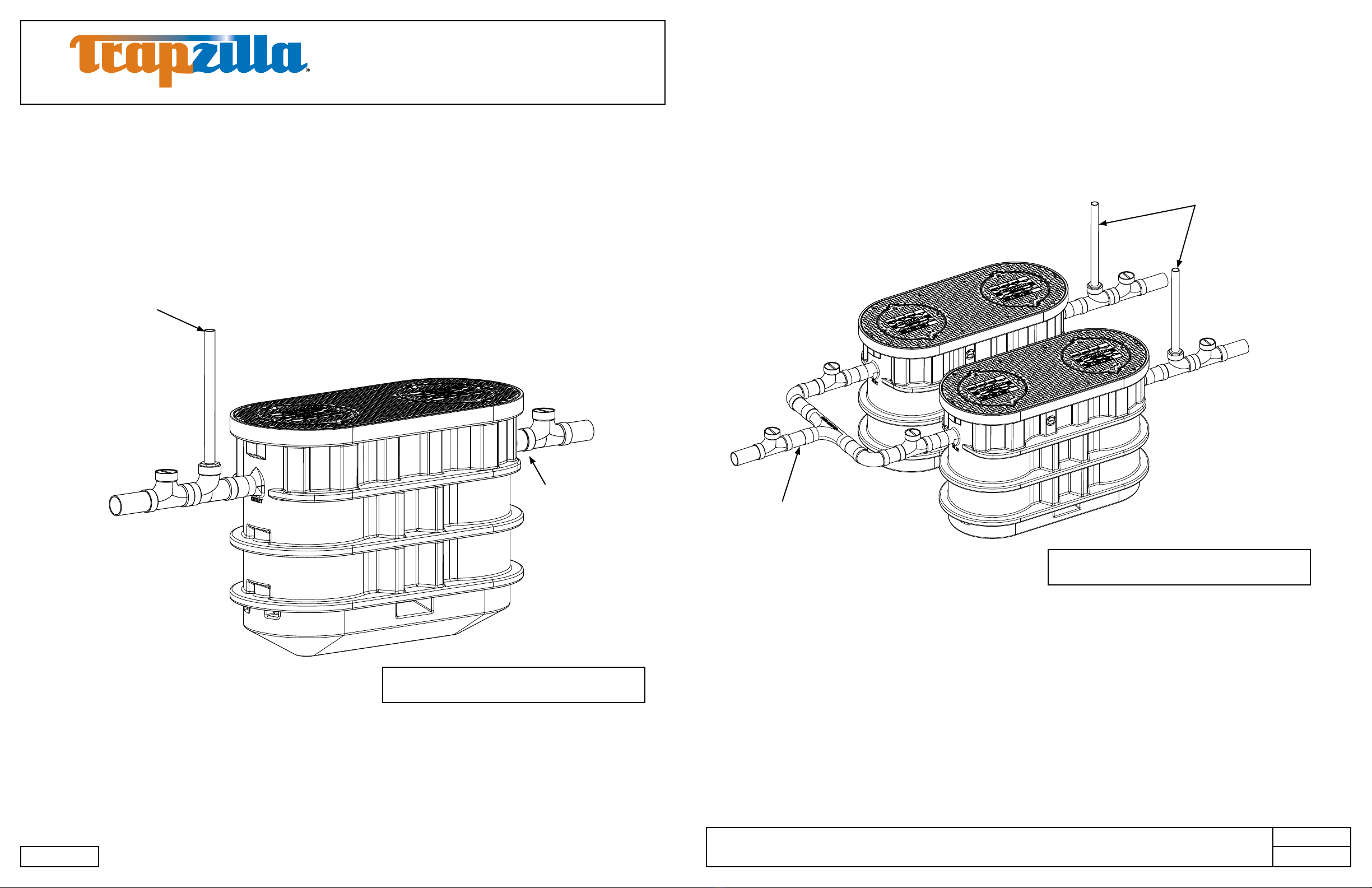
3.3 Plumbing Congurations
3.3.1 One TZ-1826
Each Trapzilla unit is shipped with a Low Head Flow Control module (see LHFC box for additional
instructions). When applicable, this needs to be installed to the inlet of the Trapzilla and connected to
a code-approved air intake. Thermaco, Inc. recommends installation of Two-Way Cleanouts on both
the Inlet and Outlet of Trapzilla® in accordance with all applicable laws, regulations and codes. These
cleanouts should match the size of the Inlet and Outlet Piping (i.e. for 4” plumbing, a 4” cleanout should
be used). A Vent on the Outlet piping is also to be installed in accordance with all applicable laws,
regulations and codes.
*Use a Two-Way Cleanout before and after all
Trapzilla Installations
Outlet
Inlet
*Cleanout
*Cleanout
Outlet Vent
(Connect to
facility vent)
Note: Drawing for reference only. Equipment must be installed in compliance with all applicable laws, regulations
and codes, including plumbing codes. Installation should be performed by a qualied plumber.
Low-Head Flow Con-
trol (not pictured) to
be installed as close
as possible to inlet
when necessary.
3.3.2 Installing Multiple Trapzilla Units in Parallel
Trapzilla Grease Interceptors should be installed in parallel with a Trapzilla Flow Splitter (MFSH-44 or
MFSH-66) diverting the ow. Place Two-Way Cleanouts before, between and after the units as shown
below, including before and after the ow splitter. Make sure to connect an outlet vent after each Trapzilla
Grease Interceptor. A Low Head Flow Control (LHFC) is shipped with each unit, and if needed should
only be installed after the rst Cleanout and before the Flow Splitter.
*Use a Two-Way Cleanout before and after all
Trapzilla Installations
1
1
2
2
3
3
4
4
A A
B B
C C
D D
THIS DRAWING CONTAINS PROPRIETARY AND PATENTED MATERIAL. THIS DRAWING MAY NOT BE REPRODUCED IN WHOLE OR PART WITHOUT
WRITTEN CONSENT FROM THERMACO, INC. POSSESSION OF THIS DRAWING DOES NOT CONSTITUTE THE RIGHT TO MANUFACTURE.
POSSESSION OF THIS DRAWING DOES CONSTITUTE AN IMPLIED NONDISCLOSURE AGREEMENT BETWEEN THERMACO, INC. AND THE HOLDER OF
THIS DRAWING. DO NOT DESTROY THIS DRAWING, IT IS THE SOLE PROPERTY OF THERMACO, INC. AND MUST BE RETURNED UPON REQUEST.
MATERIAL (UNLESS NOTED)
FINISH (UNLESS NOTED)
646 GREENSBORO STREET
PO BOX 2548, ASHEBORO, NC 27203
VOICE 336-629-4651 FAX 336-626-5739 Decimals
.XX +/- .03
.XXX +/- .015
Unless otherwise specified
Dimensions are in inches
Tolerances
Angular
+/- 1°
CHECKED SIZE REV. NO. DWG NO.
PART NO. C
SCALE RELEASE DATE SHEET OF
ENGINEERING
DRAWN DATE
THIRD ANGLE PRO JECTION
Outlet
Inlet
*Cleanout
*Cleanout
Outlet Vents
(Connect to
facility vent)
Low-Head Flow Con-
trol (not pictured) to
be installed as close
as possible to inlet
when necessary.
*Cleanout
*Cleanout
©2018 Thermaco, Inc. All rights reserved • Patented/Patents Pending • Specications subject to change without notice
Thermaco, Inc. • 646 Greensboro St. • Asheboro, N. C. 27204-2548 • (336) 629-4651 MNL-TZ-1826 11
A THERMACO® Technology
Trapzilla®Grease Interceptor
Installation and Operations Manual
TZ-1826 Models
AEF
MNL-TZ-1826 10
1
1
2
2
3
3
4
4
A A
B B
C C
D D
THIS DRAWING CONTAINS PROPRIETARY AND PATENTED MATERIAL. THIS DRAWING MAY NOT BE REPRODUCED IN WHOLE OR PART WITHOUT
WRITTEN CONSENT FROM THERMACO, INC. POSSESSION OF THIS DRAWING DOES NOT CONSTITUTE THE RIGHT TO MANUFACTURE.
POSSESSION OF THIS DRAWING DOES CONSTITUTE AN IMPLIED NONDISCLOSURE AGREEMENT BETWEEN THERMACO, INC. AND THE HOLDER OF
THIS DRAWING. DO NOT DESTROY THIS DRAWING, IT IS THE SOLE PROPERTY OF THERMACO, INC. AND MUST BE RETURNED UPON REQUEST.
MATERIAL (UNLESS NOTED)
FINISH (UNLESS NOTED)
646 GREENSBORO STREET
PO BOX 2548, ASHEBORO, NC 27203
VOICE 336-629-4651 FAX 336-626-5739 Decimals
.XX +/- .03
.XXX +/- .015
Unless otherwise specified
Dimensions are in inches
Tolerances
Angular
+/- 1°
CHECKED SIZE REV. NO. DWG NO.
PART NO. C
SCALE RELEASE DATE SHEET OF
ENGINEERING
DRAWN DATE
THIRD ANGLE PRO JECTION
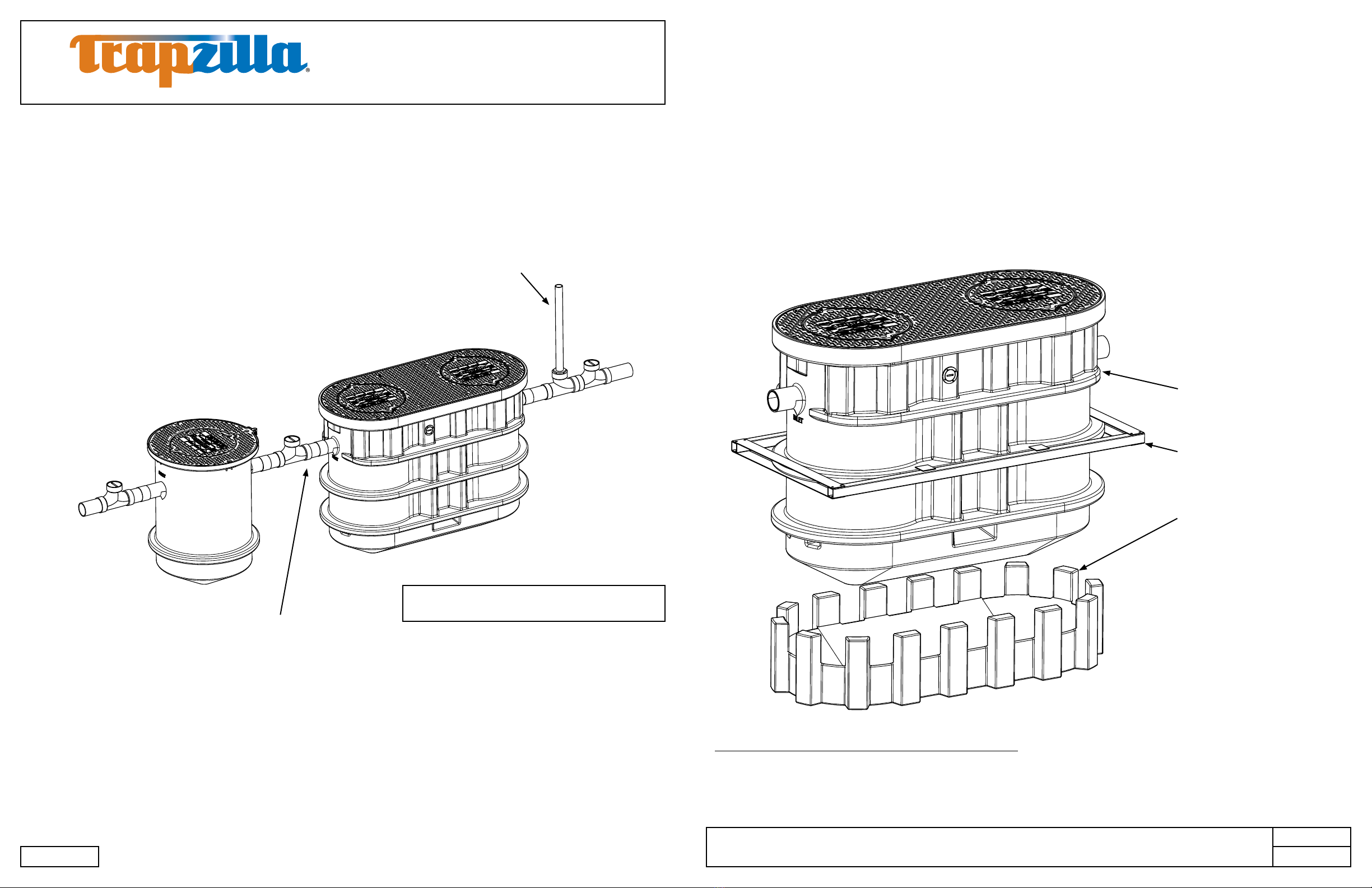
3.3.3 Installing Multiple Trapzilla Units in Series
Alternatively, two Trapzilla Grease Interceptors, Solids Separators or a combination may be installed in
series. A single Trapzilla Solids Separator and Trapzilla Grease Interceptor should always be installed
in series. Place Two-Way Cleanouts before, between and after the units as shown below. Make sure
to connect an outlet vent after the Trapzilla Grease Interceptor. A Low Head Flow Control (LHFC) is
shipped with each grease interceptor and should only be installed after the rst Cleanout and before
the rst grease interceptor.
*Use a Two-Way Cleanout before and after all
Trapzilla Installations
Outlet
Inlet
*Cleanout
*Cleanout
Outlet Vents
(Connect to
facility vent)
Low-Head Flow Control (not
pictured) to be installed as
close as possible to inlet of
rst grease interceptor.
*Cleanout
Note: Drawing for reference only. Equipment must be installed in compliance with all applicable laws, regulations
and codes, including plumbing codes. Installation should be performed by a qualied plumber.
The SSA-1826 Support Stand is a one-piece assembly with a conical center that sits on the oor.
It does not add appreciable height to the assembly.
4. Above-Ground Installation
4.1 Components for Above-Ground Installations
Using a model-specic Support Stand, a Trapzilla unit may be installed directly on top of the oor in a
location such as a basement or mechanical room.
TZ-1826-SSA comes with SSA-1826 and external brace for above-ground installations. All TZ-1826
units come with built-in 18” Risers which must be cut down and secured in eld.
The External Brace must be installed in above-ground installations or the warranty will be voided.
NOTE: SUPPORT STAND
MUST BE INSTALLED OVER
A CONTINUOUS SURFACE.
NON-CONTINUOUS
SURFACES SUCH AS GRATES
ARE NOT SUITABLE FOR
SUPPORT.
1
1
2
2
3
3
4
4
A A
B B
C C
D D
THIS DRAWING CONTAINS PROPRIETARY AND PATENTED MATERIAL. THIS DRAWING MAY NOT BE REPRODUCED IN WHOLE OR PART WITHOUT
WRITTEN CONSENT FROM THERMACO, INC. POSSESSION OF THIS DRAWING DOES NOT CONSTITUTE THE RIGHT TO MANUFACTURE.
POSSESSION OF THIS DRAWING DOES CONSTITUTE AN IMPLIED NONDISCLOSURE AGREEMENT BETWEEN THERMACO, INC. AND THE HOLDER OF
THIS DRAWING. DO NOT DESTROY THIS DRAWING, IT IS THE SOLE PROPERTY OF THERMACO, INC. AND MUST BE RETURNED UPON REQUEST.
MATERIAL (UNLESS NOTED)
FINISH (UNLESS NOTED)
646 GREENSBORO STREET
PO BOX 2548, ASHEBORO, NC 27203
VOICE 336-629-4651 FAX 336-626-5739 Decimals
.XX +/- .03
.XXX +/- .015
Unless otherwise specified
Dimensions are in inches
Tolerances
Angular
+/- 1°
CHECKED SIZE REV. NO. DWG NO.
PART NO. C
SCALE RELEASE DATE SHEET OF
ENGINEERING
DRAWN DATE
THIRD ANG LEPR OJECTION
TZ-1826
External Brace
(installation instructions on
next page)
SSA-1826

©2018 Thermaco, Inc. All rights reserved • Patented/Patents Pending • Specications subject to change without notice
Thermaco, Inc. • 646 Greensboro St. • Asheboro, N. C. 27204-2548 • (336) 629-4651 MNL-TZ-1826 13
A THERMACO® Technology
Trapzilla®Grease Interceptor
Installation and Operations Manual
TZ-1826 Models
AEF
MNL-TZ-1826 12
4.3.2 Construction of Riser for TSS-95-SSA installation in series with TZ-1826-SSA
For the installation of a TSS-95-SSA prior to the TZ-1826-SSA, a riser must be constructed to raise the
smaller unit by 8” and provide full support for the weight of the interceptor and its contents.
4.3.3 Installing Multiple TZ-1826-SSA in Series
When installing multiple Trapzilla units in series, the change in elevation from the inlet to the outlet of a unit
requires that each preceding unit be installed 1.5” higher than the unit after it. For above-ground units,
pressure treated plywood may be placed fully beneath the support stand to create the height difference.
All installations inside of a building must have a vessel vent installed and be piped to atmosphere.
4.2 Instructions for Assembling and Attaching External Brace
4.3 Instructions for Installing Multiple Trapzilla Units Above-Ground
4.3.1 Installing TZ-1826-SSA with TSS-95-SSA in Series
When installing a TZ-1826-SSA Interceptor with a TSS-95-SSA Solids Interceptor in series, the change
in elevation from the outlet of one of these smaller units to the inlet of the TZ-1826-SSA to the requires
that the preceding unit be installed 8” higher than the unit after it.
1
1
2
2
3
3
4
4
A A
B B
C C
D D
THIS DRAWING CONTAINS PROPRIETARY AND PATENTED MATERIAL. THIS DRAWING MAY NOT BE REPRODUCED IN WHOLE OR PART WITHOUT
WRITTEN CONSENT FROM THERMACO, INC. POSSESSION OF THIS DRAWING DOES NOT CONSTITUTE THE RIGHT TO MANUFACTURE.
POSSESSION OF THIS DRAWING DOES CONSTITUTE AN IMPLIED NONDISCLOSURE AGREEMENT BETWEEN THERMACO, INC. AND THE HOLDER OF
THIS DRAWING. DO NOT DESTROY THIS DRAWING, IT IS THE SOLE PROPERTY OF THERMACO, INC. AND MUST BE RETURNED UPON REQUEST.
MATERIAL (UNLESS NOTED)
FINISH (UNLESS NOTED)
646 GREENSBORO STREET
PO BOX 2548, ASHEBORO, NC 27203
VOICE 336-629-4651 FAX 336-626-5739 Decimals
.XX +/- .03
.XXX +/- .015
Unless otherwise specified
Dimensions are in inches
Tolerances
Angular
+/- 1°
CHECKED SIZE REV. NO. DWG NO.
PART NO. C
SCALE RELEASE DATE SHEET OF
ENGINEERING
DRAWN DATE
THIRD ANGLE PR OJECTION
8" ELEVATION DIFFERENCE
(MINIMUM) BETWEEN TSS
AND TZ TO ENSURE FLOW
AND TO COMPENSATE FOR
HEIGHT DIFFERENCES. A
RISER MADE FROM TREATED
LUMBER OR CONCRETE MAY
BE USED.
LAMINATED
PLYWOOD
RISER
FRAMED FLOOR RISER
WITH PLYWOOD TOP
FOR CONTINUOUS
SUPPORT
36" SQUARE MINIMUM
Note: Drawing for reference only. Equipment must be installed in compliance with all applicable laws, regulations
and codes, including plumbing codes. Installation should be performed by a qualied plumber.
1
1
2
2
3
3
4
4
A A
B B
C C
D D
THIS DRAWING CONTAINS PROPRIETARY AND PATENTED MATERIAL. THIS DRAWING MAY NOT BE REPRODUCED IN WHOLE OR PART WITHOUT
WRITTEN CONSENT FROM THERMACO, INC. POSSESSION OF THIS DRAWING DOES NOT CONSTITUTE THE RIGHT TO MANUFACTURE.
POSSESSION OF THIS DRAWING DOES CONSTITUTE AN IMPLIED NONDISCLOSURE AGREEMENT BETWEEN THERMACO, INC. AND THE HOLDER OF
THIS DRAWING. DO NOT DESTROY THIS DRAWING, IT IS THE SOLE PROPERTY OF THERMACO, INC. AND MUST BE RETURNED UPON REQUEST.
MATERIAL (UNLESS NOTED)
FINISH (UNLESS NOTED)
646 GREENSBORO STREET
PO BOX 2548, ASHEBORO, NC 27203
VOICE 336-629-4651 FAX 336-626-5739 Decimals
.XX +/- .03
.XXX +/- .015
Unless otherwise specified
Dimensions are in inches
Tolerances
Angular
+/- 1°
CHECKED SIZE REV. NO. DWG NO.
PART NO. C
SCALE RELEASE DATE SHEET OF
ENGINEERING
DRAWN DATE
THIRD ANGLE PRO JECTION
1.5" ELEVATION DIFFERENCE
(MINIMUM) BETWEEN FRONT
UNIT AND REAR UNIT TO
ENSURE FLOW AND TO
COMPENSATE FOR HEIGHT
DIFFERENCES
1
1
2
2
3
3
4
4
A A
B B
C C
D D
THIS DRAWING CONTAINS PROPRIETARY AND PATENTED MATERIAL. THIS DRAWING MAY NOT BE REPRODUCED IN WHOLE OR PART WITHOUT
WRITTEN CONSENT FROM THERMACO, INC. POSSESSION OF THIS DRAWING DOES NOT CONSTITUTE THE RIGHT TO MANUFACTURE.
POSSESSION OF THIS DRAWING DOES CONSTITUTE AN IMPLIED NONDISCLOSURE AGREEMENT BETWEEN THERMACO, INC. AND THE HOLDER OF
THIS DRAWING. DO NOT DESTROY THIS DRAWING, IT IS THE SOLE PROPERTY OF THERMACO, INC. AND MUST BE RETURNED UPON REQUEST.
MATERIAL (UNLESS NOTED)
FINISH (UNLESS NOTED)
646 GREENSBORO STREET
PO BOX 2548, ASHEBORO, NC 27203
VOICE 336-629-4651 FAX 336-626-5739 Decimals
.XX +/- .03
.XXX +/- .015
Unless otherwise specified
Dimensions are in inches
Tolerances
Angular
+/- 1°
CHECKED SIZE REV. NO. DWG NO.
PART NO. C
SCALE RELEASE DATE SHEET OF
ENGINEERING
DRAWN DATE
THIRD ANGLE PR OJECTION
PLYWOOD STACK RISER
ASSEMBLE SHEETS OF PRESSURE
TREATED PLYWOOD (MINIMUM
36 INCHES [92CM] SQUARE) TO
THE DESIRED HEIGHT. SECURE
EACH LAYER TO THE ONE BELOW
WITH CORROSION RESISTANT
SCREWS.
FRAMED FLOOR RISER
CONSTRUCT A FLOOR SUPPORT FRAME
(MINIMUM 36 INCHES [92CM] SQUARE) FROM
PRESSURE TREATED LUMBER OF 2 IN [50MM]
NOMINAL THICKNESS AND OF THE DESIRED
HEIGHT. SPACE FRAME MEMBERS NO MORE THAN
10 IN [25CM] APART. COVER THIS STRUCTURE
WITH PRESSURE TREATED PLYWOOD. SECURE ALL
JOINTS WITH CORROSION RESISTANT SCREWS.
1
2
3
1
1
2
2
3
3
4
4
A A
B B
C C
D D
THIS DRAWING CONTAINS PROPRIETARY AND PATENTED MATERIAL. THIS DRAWING MAY NOT BE REPRODUCED IN WHOLE OR PART WITHOUT
WRITTEN CONSENT FROM THERMACO, INC. POSSESSION OF THIS DRAWING DOES NOT CONSTITUTE THE RIGHT TO MANUFACTURE.
POSSESSION OF THIS DRAWING DOES CONSTITUTE AN IMPLIED NONDISCLOSURE AGREEMENT BETWEEN THERMACO, INC. AND THE HOLDER OF
THIS DRAWING. DO NOT DESTROY THIS DRAWING, IT IS THE SOLE PROPERTY OF THERMACO, INC. AND MUST BE RETURNED UPON REQUEST.
MATERIAL (UNLESS NOTED)
FINISH (UNLESS NOTED)
646 GREENSBORO STREET
PO BOX 2548, ASHEBORO, NC 27203
VOICE 336-629-4651 FAX 336-626-5739 Decimals
.XX +/- .03
.XXX +/- .015
Unless otherwise specified
Dimensions are in inches
Tolerances
Angular
+/- 1°
CHECKED SIZE REV. NO. DWG NO.
PART NO. C
SCALE RELEASE DATE SHEET OF
ENGINEERING
DRAWN DATE
THIRD ANG LE PRO JECTION
RAIL
PLATE
UPPER SUPPORT RIB
CENTER SUPPORT RIB
LOWER SUPPORT RIB
1. PLACE ONE RAIL ON
EACH SIDE OF TZ-1826
WITH TABS ON TOP AND
BOTTOM OF CENTER
SUPPORT RIB.
2. PLACE ONE PLATE ON TOP
OF CENTER SUPPORT RIB AND
ONE ON THE BOTTOM ON EACH
END OF THE TZ-1826. ALIGN
HOLES IN THE PLATES AND RAILS. 3. INSERT 2 BOLTS
INTO HOLES AT EACH
CORNER. ADD NUTS
AND TIGHTEN TO
COMPLETE ASSEMBLY.

©2018 Thermaco, Inc. All rights reserved • Patented/Patents Pending • Specications subject to change without notice
Thermaco, Inc. • 646 Greensboro St. • Asheboro, N. C. 27204-2548 • (336) 629-4651 MNL-TZ-1826 15
A THERMACO® Technology
Trapzilla®Grease Interceptor
Installation and Operations Manual
TZ-1826 Models
AEF
MNL-TZ-1826 14
4.3.4 Installation of Pipe Hangers with Above-Ground Units
Trapzilla units installed indoors, above-ground require the use of pipe hangers (purchased separately)
to properly support plumbing and reduce stress on connections with unit. Thermaco recommends the
use of four (4) Zinc-plated Steel Loop Style hangers with 1000 lbs. work load limit for a single Trapzilla
installation with two (2) hangers placed before inlet side cleanout and two (2) hangers placed after nal
cleanout.
Place each pair of hangers 35” apart (space-permitting) and no closer than 5” from any joint. When
multiple units are installed place one (1) additional pipe hanger in between each unit, leaving 5” distance
from unit and cleanout. Follow pipe hanger manufacturer’s instructions for physical installation.
5. In-Ground Installation Instructions
5.1 Plumbing Instructions for Single TZ-1826 Installed In-Ground
A Trapzilla unit may also be installed in the ground inside or outside of the facility. For instances
where the facility drainage piping requires an extension collar that is more than the 18” provided
by the built-in extension, the ECA-TZ-29 Extension Collar Assembly may be installed to align the
Trapzilla inlet with the drainage piping. Thermaco, Inc. strongly recommends surrounding the
in-ground Trapzilla with concrete to provide additional structural strength and to offset buoyancy
effects. For Buoyancy Calculations & suggested concrete fill quantities please see page 17.
In-Ground Installations inside of a building must have a vessel vent installed and be piped to
atmosphere.
Note: Drawing for reference only. Equipment must be installed in compliance with all applicable laws, regulations
and codes, including plumbing codes. Installation should be performed by a qualied plumber.
Outlet Vent -
extend to grade
and cover or con-
nect to facility
Vessel Vent -
to atmosphere
Built-in 18”
extension collars
Trapzilla cover -
placed on top-most
extension collar, to
be accessible from
ground level
Grade
Two-way cleanout
before and after
each unit, extend to
grade.
Concrete surround-
ing unit body and
extension collar.
Inlet Outlet
5/8”-11 Rods
Loop-Style
Pipe Hanger
35” between
hangers
5” between hangers
and any joints
Unit must be supported by
Trapzilla Support Stand Assembly.
No Trapzilla unit may be hung
using pipe hangers.

©2018 Thermaco, Inc. All rights reserved • Patented/Patents Pending • Specications subject to change without notice
Thermaco, Inc. • 646 Greensboro St. • Asheboro, N. C. 27204-2548 • (336) 629-4651 MNL-TZ-1826 17
A THERMACO® Technology
Trapzilla®Grease Interceptor
Installation and Operations Manual
TZ-1826 Models
AEF
MNL-TZ-1826 16
5.3 Concrete Specications for In-Ground Installation
In order to offset the effects of buoyancy caused by groundwater (high water tables), strengthen the
sideload of the unit, and prevent movement of the unit in the event of shifting earth, Thermaco, Inc.
recommends concrete be poured around the entirety of Trapzilla®units installed in-ground in the amounts
of concrete specied in the table below. The concrete must to be poured continuously and completely
surrounding the Trapzilla®body (and Extension Collars if applicable) to ensure proper strength and
security at a compression strength of 4000 psi (C28/35).
5.4 Concrete Calculations for TZ-1826 Models/Components*
Amount of Concrete
Trapzilla Model Weight in lbs. (Kg) Volume in Cubic Yards (m3)
TZ-1826 3950 1.0
ECA-TZ-29 (each) 600 0.20
5.2 Plumbing Instructions for TZ-1826 with Optional ECA-TZ-29 Extension Collars (purchased
separately)
In some cases, TZ-1826 may be installed in locations where built-in extension collar will not reach grade.
In these cases, the two-piece ECA-TZ-29 Extension Collar (purchased separately) may be used to make
lid accessible at ground level. Follow instructions included in ECA-TZ-29 packaging for installations.
Each TZ-1826 would require two (2) ECA-TZ-29 if pipe depth requires.
* In-ground installation instructions only applicable for units installed where center of outlet pipe is
no more than 60” below grade. For all installations deeper than this, Thermaco must be contacted
to verify site conditions and provide further instructions for proper installation. Failure to abide by
this instruction will result in voiding the warranty of the unit.
In-Ground Installations inside of a building must have a vessel vent installed and piped to at-
mosphere.
Note: Drawing for reference only. Equipment must be installed in compliance with all applicable laws, regulations
and codes, including plumbing codes. Installation should be performed by a qualied plumber.
ECA-TZ-29
Two-piece extension
collar with 4-29” of
extension. Connect
bottom piece to built-
in extension collar
and use original lid
provided.
Built-in
extension
Follow instructions
on pages 18-19 to
set built-in extension
collar. When pos-
sible adjust height
of built-in extension
collar before trimming
ECA-TZ-29.
©2018 Thermaco, Inc. All rights reserved • Patented/Patents Pending • Specications subject to change without notice
Thermaco, Inc. • 646 Greensboro St. • Asheboro, N. C. 27204-2548 • (336) 629-4651 MNL-TZ-1826 19
A THERMACO® Technology
Trapzilla®Grease Interceptor
Installation and Operations Manual
TZ-1826 Models
AEF
MNL-TZ-1826 18
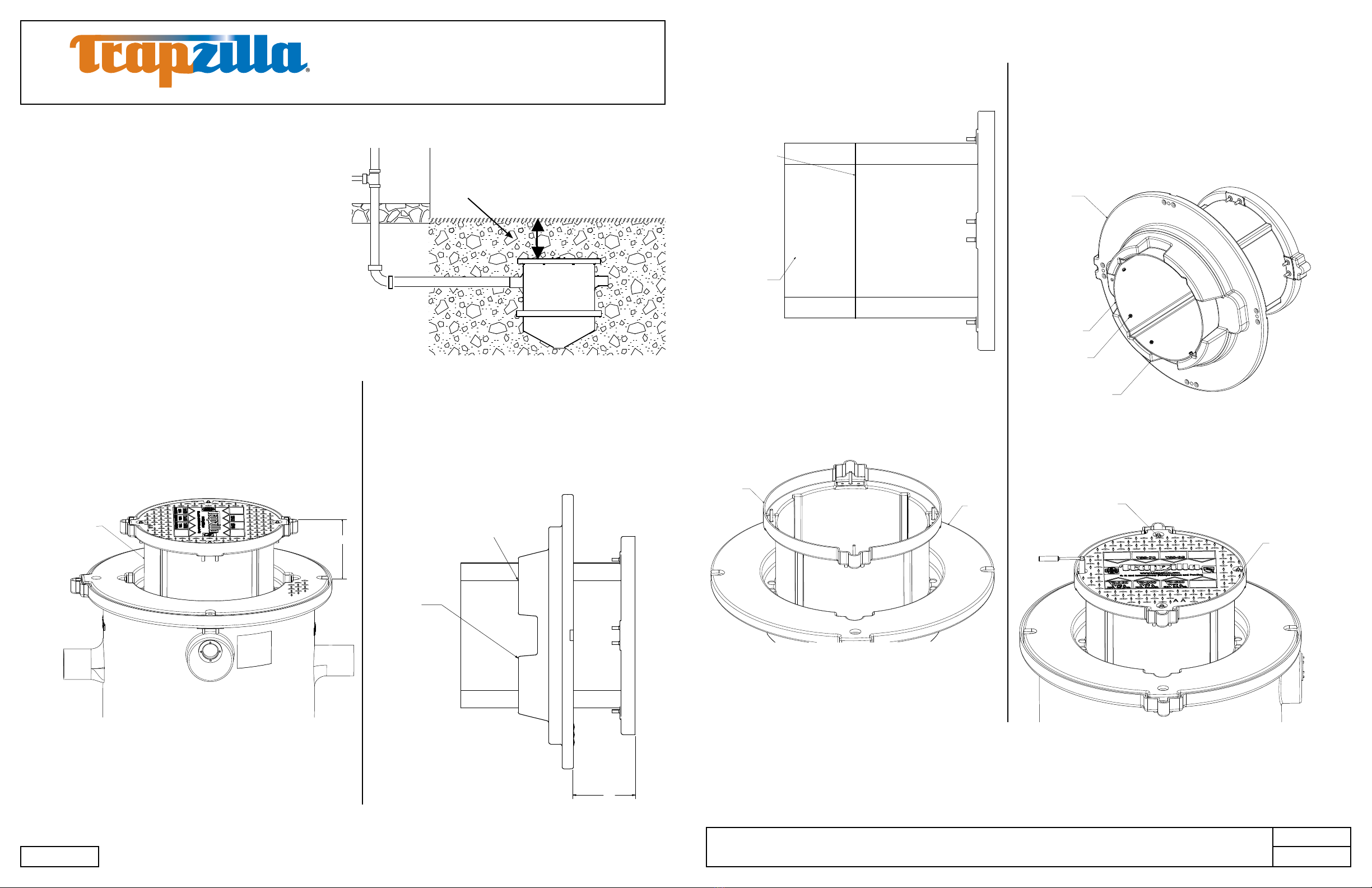
5.5 Trimming and Setting the ECA-TZ-18 Single-Piece Extension Collar
In-Ground Trapzilla Models ship with a built-in,
single-piece, 18” extension collar that must be
trimmed and then set to the correct height to
bring the Solid Top Cover to grade.
Follow the steps below to set the extension
collar prior to backfilling the hole with
concrete.
Amount of extension collar needed to bring
Solid Top Cover to grade.
Step 2: Remove the extension collar adapter ring from the
unit with the extension collar still in place. On the underside
of the cover, mark the excess extension collar length at the
bottom of the four (4) “skirt” portions of the adapter ring.
Check the extension collar height dimension frequently
during this marking to ensure that the collar has not moved.
Extend this mark between the gaps in the “skirt” so that the
collar is marked all around.
Step 1: With the Trapzilla unit installed in its permanent
location, raise the telescoping extension collar to nished
grade or oor level. Measure the height from the top of the
unit to this nished extension collar height and record this
dimension.
Note: If the oor will have a tile covering, allow for the tile
thickness when determining the extension collar height.
8.25"
Extension collar
Skirt
Mark excess extension collar length
at the four (4) "skirt" portions of
the adapter ring.
8.25
Step 5: Working from the bottom of the assembly, install
eight (8) self-drilling, self-tapping screws (provided) through
the extension collar wall and into the adapter ring. Two of
these screws should be installed in each of the four (4) skirt
areas of the adapter ring. Check the extension collar height
dimension frequently during this operation to ensure that the
collar has not moved. Note: Use caution when tightening
these screws to ensure that they do not strip.
Step 6: Place the adapter ring/extension collar assembly
onto the Trapzilla unit. Position the small cover onto the
extension collar. Secure the adapter ring and the small
cover with the brass nuts and at washers provided. Seal
the gap between the 18” extension collar and extension
collar adapter ring using a silicone sealant.
Step 3: Remove the extension collar from the adapter ring
and, with an appropriate saw, cut along the line created in
Step 2 to remove the excessive extension collar.
Step 4: Reinsert the extension collar into the adapter ring
ensuring that the cover alignment key on the extension
collar is aligned with its recess in the adapter ring.
Reset the extension collar height to the dimension
determined in Step 1.
Line marking the bottom
of the "skirt" (adapter
ring has
been removed
for clarity)
Excess part of
extension collar
to be discarded
after cutting
along line
Reinsert extension collar into adapter
ring to insure alignment.
Adapter ring
Extension collar
Modified extension collar
Self-tapping screws
8 Places
Adapter ring
"Skirt"
5/16-inch Hex Nut
4 Places
5/16-inch Washer
4 Places
Note: Tighten down the flat
washers and brass nuts using
a 5/16-inch socket and rachet.
Do not over tighten.
Note: Drawing for reference only. Equipment must be installed in compliance with all applicable laws, regulations
and codes, including plumbing codes. Installation should be performed by a qualied plumber.
IMPORTANT: Excess extension collar must be trimmed on all units. Do not allow
additional extension collar to extend beyond bottom of adapter ring. On units
where extension collar is completely recessed, the extension collar should still
be secured and the excess extension removed as in step 3.
©2018 Thermaco, Inc. All rights reserved • Patented/Patents Pending • Specications subject to change without notice
Thermaco, Inc. • 646 Greensboro St. • Asheboro, N. C. 27204-2548 • (336) 629-4651 MNL-TZ-1826 21
A THERMACO® Technology
Trapzilla®Grease Interceptor
Installation and Operations Manual
TZ-1826 Models
AEF
MNL-TZ-1826 20
6. Unit Maintenance
6.1 Measuring Grease/Solids Levels
Due to its unique design, Trapzilla is capable of retaining high quantities of grease in a compact footprint.
Therefore, unlike traditional interceptors, Trapzilla can hold an extraordinarily high percentage of its
volume in grease without losing separation efciency. To determine the current levels of grease/solids
in your Trapzilla grease interceptor, follow the instructions below.
1. Remove four nuts/washers securing the 22” Solid Top Cover.
2. Place a grease/sludge dipstick into the center of the opening, making sure that it goes through the
hole in the horizontal bafe.
3. Once the dipstick has found its natural resting place at the lowest point in the conical shaped bottom,
take the measurement.
4. Remove dipstick and compare grease/sludge levels to the corresponding unit in the charts below.
Grease Solids
Total
Capacity
(depth):
Ready to
pump at
(depth):
Total
Capacity
(height):
Ready to
pump at
(height):
TZ-1826 25” 20” 13.5” 10.75”
Take solids/sludge measurement from
bottom of unit upward and compare to
chart above.
Take grease measurement from top of
liquid level downward and compare to
chart above.
Note: Drawing for reference only. Equipment must be installed in compliance with all applicable laws, regulations
and codes, including plumbing codes. Installation should be performed by a qualied plumber.
6.2 Pumping/Servicing Unit
Periodically, the Trapzilla® unit will need to be serviced which involves pumping out all accumulated
grease and solids. Pumping frequency may be set at a regular interval by sewer district (every 30-90
days). If not, determine pumping frequency using instructions in 6.1 to periodically measure grease/
solids levels to determine appropriate timing for pumping. Follow instructions below to pump/clean out
TZ-1826.
1. Each lid has four brass nuts securing the lid. Remove the four brass nuts from the bolts and fully
remove the 22” lid to pump out. It is not necessary to remove adapter lid to pump out Trapzilla.
2. Begin by taking the grease from the top of the main chamber until all grease is removed.
3. Upon reaching the horizontal bafe, you will see a hole through which you may access the rest of
the grease and the solids. Be sure to lower the hose all the way to the bottom of the Trapzilla unit
on the outlet side so that solids may be entirely removed. The conical shape and natural grade of
the unit will allow solids and grease to run to outlet side of unit.
4. Have kitchen run water into unit to ush any remaining solids to the outlet end of the unit.
5. If necessary, use a water hose with spray nozzle to rinse off inside of unit.
6. Secure lids in place and instruct kitchen to run water into unit until full.
DO NOT use mechanical crust breaking devices to break down any mat that has formed inside the
Trapzilla unit.
DO NOT use grinding augers in maintenance of the Trapzilla unit.
1
1
2
2
3
3
4
4
A A
B B
C C
D D
THIS DRAWING CONTAINS PROPRIETARY AND PATENTED MATERIAL. THIS DRAWING MAY NOT BE REPRODUCED IN WHOLE OR PART WITHOUT
WRITTEN CONSENT FROM THERMACO, INC. POSSESSION OF THIS DRAWING DOES NOT CONSTITUTE THE RIGHT TO MANUFACTURE.
POSSESSION OF THIS DRAWING DOES CONSTITUTE AN IMPLIED NONDISCLOSURE AGREEMENT BETWEEN THERMACO, INC. AND THE HOLDER OF
THIS DRAWING. DO NOT DESTROY THIS DRAWING, IT IS THE SOLE PROPERTY OF THERMACO, INC. AND MUST BE RETURNED UPON REQUEST.
MATERIAL (UNLESS NOTED)
FINISH (UNLESS NOTED)
646 GREENSBORO STREET
PO BOX 2548, ASHEBORO, NC 27203
VOICE 336-629-4651 FAX 336-626-5739 Decimals
.XX +/- .03
.XXX +/- .015
Unless otherwise specified
Dimensions are in inches
Tolerances
Angular
+/- 1°
CHECKED SIZE REV. NO. DWG NO.
PART NO. C
SCALE RELEASE DATE SHEET OF
ENGINEERING
DRAWN DATE
THIRD ANGLE PRO JECTION
1
1
2
2
3
3
4
4
A A
B B
C C
D D
THIS DRAWING CONTAINS PROPRIETARY AND PATENTED MATERIAL. THIS DRAWING MAY NOT BE REPRODUCED IN WHOLE OR PART WITHOUT
WRITTEN CONSENT FROM THERMACO, INC. POSSESSION OF THIS DRAWING DOES NOT CONSTITUTE THE RIGHT TO MANUFACTURE.
POSSESSION OF THIS DRAWING DOES CONSTITUTE AN IMPLIED NONDISCLOSURE AGREEMENT BETWEEN THERMACO, INC. AND THE HOLDER OF
THIS DRAWING. DO NOT DESTROY THIS DRAWING, IT IS THE SOLE PROPERTY OF THERMACO, INC. AND MUST BE RETURNED UPON REQUEST.
MATERIAL (UNLESS NOTED)
FINISH (UNLESS NOTED)
646 GREENSBORO STREET
PO BOX 2548, ASHEBORO, NC 27203
VOICE 336-629-4651 FAX 336-626-5739 Decimals
.XX +/- .03
.XXX +/- .015
Unless otherwise specified
Dimensions are in inches
Tolerances
Angular
+/- 1°
CHECKED SIZE REV. NO. DWG NO.
PART NO. C
SCALE RELEASE DATE SHEET OF
ENGINEERING
DRAWN DATE
THIRD ANG LE PRO JECTION
2
3

©2018 Thermaco, Inc. All rights reserved • Patented/Patents Pending • Specications subject to change without notice
Thermaco, Inc. • 646 Greensboro St. • Asheboro, N. C. 27204-2548 • (336) 629-4651 MNL-TZ-1826 23
A THERMACO® Technology
Trapzilla®Grease Interceptor
Installation and Operations Manual
TZ-1826 Models
AEF
MNL-TZ-1826 22
7. Limited Warranty and Remedy
Thermaco, Inc. warrants to the original user that the equipment manufactured by Thermaco and delivered
with this warranty (the “Product”) shall be free from material defects in workmanship and materials during
the lifetime of the plumbing system in which the Product is initially installed.
Any claim under this warranty must be made in writing to Thermaco at 646 Greensboro Street, Asheboro,
NC 27203 promptly after discovery of the defect and the Product must be delivered, prepaid, to
Thermaco, together with proof of purchase and a return authorization number issued by Thermaco. If
Thermaco determines that the Product is defective, Thermaco’s sole obligation, and the purchaser’s
sole and exclusive remedy, is the repair or replacement, at Thermaco’s option, of the defective Product.
This warranty shall not cover any defect or damage resulting directly or indirectly from: (i) failure to
properly install, operate or maintain the Product in accordance with Thermaco’s instructions, including,
without limitation, use in excess of rated ow, installation deeper than manufacturer’s recommendation
or in conjunction with unapproved components, use to remove emulsied fats and oils or use that fails
to comply with applicable laws, regulations or codes; (ii) damage in transit, handling or installation; (iii)
modications, adjustments, or alterations of the Product; (iv) disassembly of components other than as
required for prescribed maintenance; or (v) any other causes not arising out of defects in workmanship
or materials. Thermaco shall not be responsible for damage to Products resulting from ultraviolet light
exposure, vault ooding, sewer line back-up, pumping or lift station failure, ambient water ow, freezing, or
other sources of water damage. Costs for any service, adjustment, removal, repair, packing, or otherwise
incurred with respect to the Product prior to submission for warranty are the responsibility of purchaser.
No distributor, sales representative or other person is authorized to make any warranty statements
on behalf of Thermaco regarding Products other than as provided herein. This statement of warranty
supersedes any quote, brochure, or other statement or document with respect to warranty of Thermaco
products.
EXCEPT AS EXPRESSLY SET FORTH ABOVE,THERMACO MAKES NO REPRESENTATIONS,
WARRANTIES OR GUARANTEES, EITHER EXPRESSED OR IMPLIED, INCLUDING, WITHOUT
LIMITATION, AS TO MERCHANTABILITY OR FITNESS FOR A PARTICULAR PURPOSE, WHETHER
OR NOT THERMACO HAD KNOWLEDGE OF PURCHASER’S PARTICULAR REQUIREMENTS OR
NEEDS, OR WITH RESPECT TO ODOR GENERATION OR OTHER INCIDENTALS RELATING TO
USE OF THE PRODUCT.
The sole and exclusive remedy with respect to this warranty or any other claim relating to defects or any
other condition or use of Products, however caused, and whether such claim is based upon warranty,
contract, tort, strict liability or any other theory, is LIMITED to the repair or replacement of the Product,
excluding any cost to remove or install the Product or, at Thermaco’s option, repayment of the purchase
price. IN NO EVENT SHALL THERMACO BE LIABLE, WHETHER IN CONTRACT, WARRANTY, TORT
(INCLUDING NEGLIGENCE), STRICT LIABILITY, INDEMNITY OR ANY OTHER LEGAL THEORY,
FOR INCIDENTAL OR CONSEQUENTIAL DAMAGES. UNDER NO CIRCUMSTANCES WILL THE
AGGREGATE LIABILITY OF THERMACO FOR ANY CAUSE OF ACTION RELATED TO THE PRODUCT
COVERED HEREBY EXCEED THE NET PURCHASE PRICE RECEIVED BY THERMACO FOR THE
PRODUCT.
Note: Do not Pressure/Hydrostatic test our units.
Table of contents
Other THERMA Industrial Equipment manuals

THERMA
THERMA Big Dipper IS Series Installation instructions

THERMA
THERMA Internal Strainer Series Installation instructions

THERMA
THERMA Big Dipper 51000 Series User manual

THERMA
THERMA Big Dipper 51000 Series User manual

THERMA
THERMA Big Dipper 40000 Series User manual

THERMA
THERMA Big Dipper 51000 Series User manual


