FINO 86000 Operation manual

FINO Stereo-Mikroskop
86000
86001
Original FINO
Germany
Gebrauchsinformation•User Information•Mode d’emploi
Información sobre el uso•Informazioni d’uso
Gebruiksaanwijzing•Instrukcja stosowania
FINO
•der feine Unterschied•the fine difference•la fine différence•la fina diferencia•la fine differenza
86000 86001
mit Stativ mit Gelenkarm
with table stand with articulated arm
avec trépied de table avec un bras articulé
con el pie de sobremesa con el brazo articulado
con stativo con braccio snodato
met statief met scharnierarm
se stativem s kloubovým ramenem
med stativ med ledad arm
állvánnyal csuklós karral

Version 1/2016. Read the operating instructions before commencing with any work!
1. Fields of application 3
2. Device setup 3
3. Safety precautions 4
4. Getting started 4
• Prior to commissioning • location
5. Handling 4
• Using with a stand (item no. 86000)
• Using with a joint arm (item no. 86001)
• Working with an LED ring light
6. Service and maintenance 7
7. Storage 7
8. Technical data 7
9. Delivery forms 7
10. Guarantee 7
11. Disposal 8
CONTENTS
2

1. Fields of application
For optimum control over all laboratory work. The
adjustable magnification enables maximum micro-
metre (μm) precision. Fine-tuning of the objective
height using the round adjustment screws provided
on both sides.
2. Device setup
1Ocular
2Dioptre compensation
3Clamping screw for microscope head
4Objective tube
5Drive knob for height adjustment
6Drive box with stand compartment
7Locking knob (for locking when using
the table stand)
8Ocular viewfinders
9Objectives
10 Episcopic illumination (ring light)
11 Plastic screws for episcopic illumination
(ring lights)
12 Socket for connecting the mains adapter cable
13 On/off switch for episcopic illumination
(ring light)
14 MAX-MIN control
15 Specimen stage
16 Clamping screw for specimen stage
17 Table stand
3. Safety precautions
Warning! Failure to observe this safety
information can result in electric shock! Keep
the device out of the reach of children.
• Only connect the episcopic illumination
(ring light) of the device to a properly
connected mains socket with a mains voltage of
230 V/50 Hz using the mains adapter supplied.
• Check the mains adapter, power cable and
device for damage prior to operation.
• If damage is identified, take the device
out of service and ensure that it cannot be put
back into operation. Have the device repaired
by an authorised specialist or by FINO GmbH.
• Do not open or repair the adapter housing,
otherwise safety is not ensured and the warranty
with become void.
• Protect the device against damp and
moisture.
• The mains adapter includes protection against
overheating and switches itself off automatically
after four hours of continuous operation. The
device must be allowed to stand for approx. one
hour before it may be switched on again.
3
ENU
It is essential to read the instructi-
ons for use carefully prior to ope-
ration and to keep these readily
available.
This symbol indicates safety pre-
cautions where non-compliance
can lead to risks for persons.
This symbol indicates safety pre-
cautions where non-compliance
can lead to damage of the device
and its function.

Information on disconnecting from the mains:
• Unplug the mains adapter from the mains socket
in order to fully disconnect the device from the
mains.
• So that the mains adapter can be unplugged
immediately in an emergency, position the device
so that access to the mains socket is never
obstructed.
• When the device is not in use, disconnect the
mains adapter from the mains socket in order
to exclude the risk of fire, prevent unintended
activation, and save energy.
• Do not touch the mains adapter when your hands
are wet as this could cause a short circuit or
electric shock.
• Disconnect the mains adapter directly from
the socket; do not pull on the power cable.
• Do not squash the power cable, knot it,
or tie it to another cable.
• When laying the power cable, ensure that
no-one can trip over it.
4. Getting started
4.1 Prior to commissioning
Before first operation check the item for transport
damages. Claim any transport damages immediately
with the supplier.
Check the device for its proper condition. In
particular, check the mains connection for
damage, such as pinching, cracks or ageing! Do not
commence operation if the mains connection is
damaged! Check the nominal voltage of the device
prior to connecting to the mains. The voltage given
on the type plate must correspond to the local mains
voltage. The mains connection plug is to be plugged
into a grounded, protected mains socket.
4.2 Location
Only operate the device in enclosed areas
that are not exposed to environmental
factors. Install the device on a dry, even surface.
Select the location so that the device is not exposed
to high temperatures, direct sunlight, strong vibra-
tions, blows or impacts.
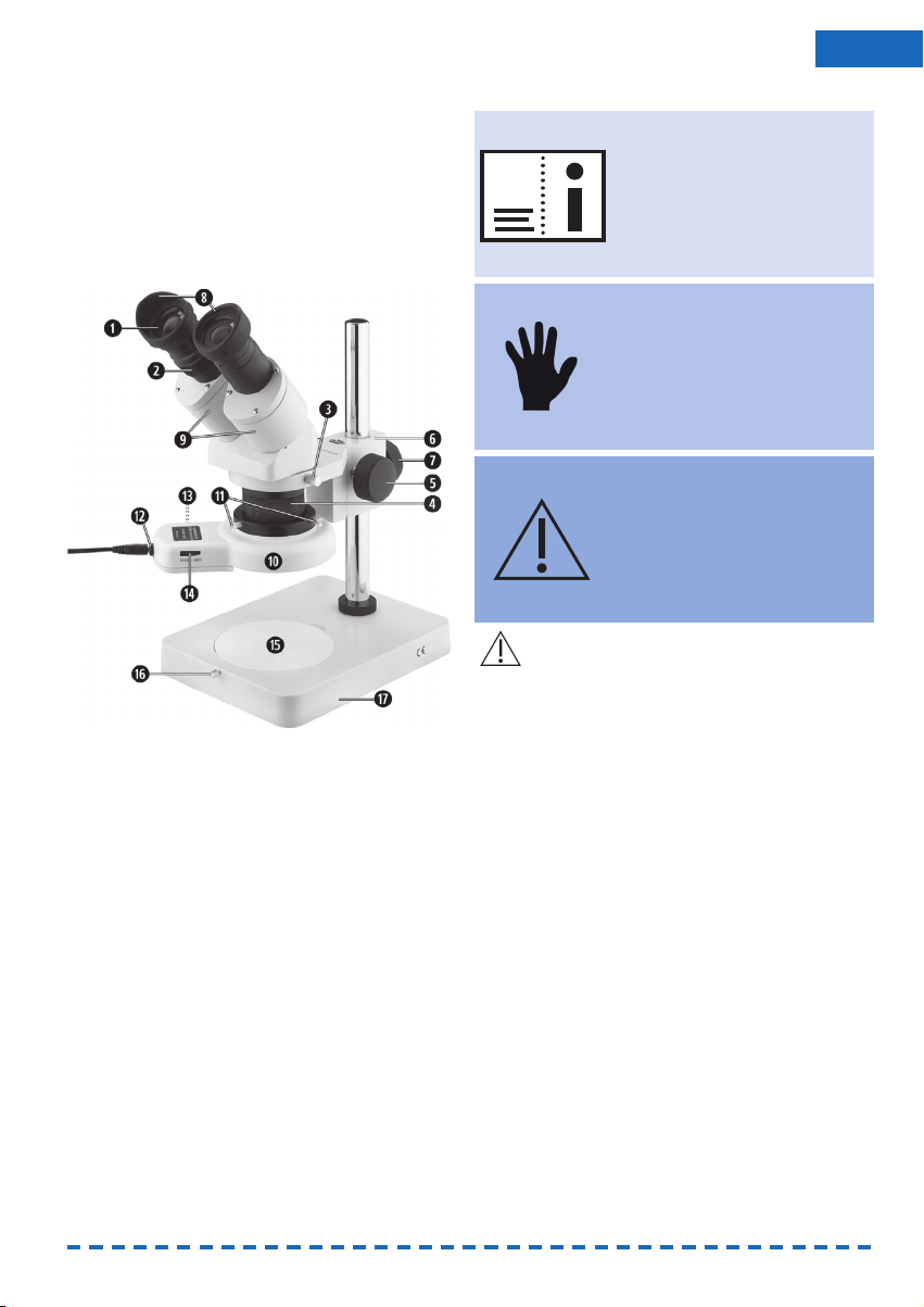
5. Handling
5.1 Using with a stand (item no. 86000)
The device is supplied almost entirely pre-assem-
bled.
• Raise the microscope knob a few centimetres
using the drive knob (5).
• Loosen the clamping screw for the microscope
head (3) and turn the microscope knob so that
the oculars (1) are facing the user. Secure the
clamping screw (3) again.
• Place both ocular viewfinders (8) on the oculars
(1).
• Unscrew the protective cap from the objective
tube (4) by turning it anticlockwise.
• Look through both oculars (1) and adjust the ocu-
lar distance in line with the interpupillary distance
by turning the objectives (9) inwards or outwards.
• For the required contrast in each case, select
either the black or the white side of the specimen
stage (15). To secure the stage, turn the clamping
screw (16) tightly by hand.
• Place the specimen to be viewed under the
microscope on the specimen stage.
• In the case of larger specimens, the distance
setting selected using the drive knobs at the side
may not be sufficient.
Adjust the distance using the locking knob (7).
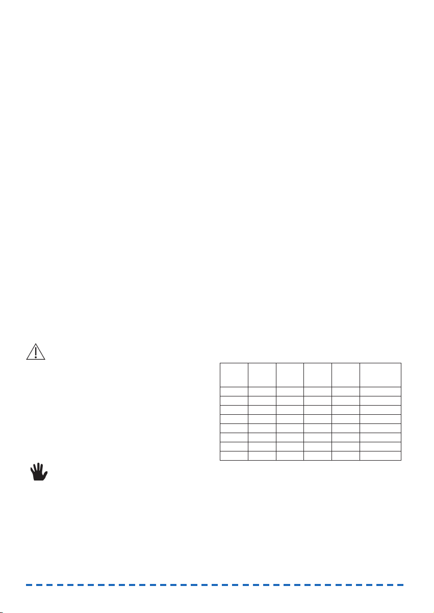
Guide values:
W= Widefield; Oculars 10x (supplied), other magni-
fications optionally available.
• Required magnification (1x or 2x) by turning the
objective tube (4) by 90° in each case.
• For fine adjustment, use the drive button (5) to
modify the distance to the object in order to
achieve maximum image precision.
• Set dioptre compensation (2) to suit individual
requirements.
Objective
magnification
Ocular
magnification
Overall
magnification
Working
distance(mm)
Field of view
ø (mm)
Field number =
Field of view ø
(mm) x objective
magnification
1x W 5x 5x 79 20 20
2x W 5x 10x 84 10 20
1x W 10x 10x 83 19 19
2x W 10x 20x 83 9,5 19
1x W 15x 15x 83 12,4 12,4
2x W 15x 30x 83 6,2 12,4
1x W 20x 20x 83 9,6 9,6
2x W 20x 40x 82 4,8 9,6
4

• The working distance and field of vision can be
further increased using the optional FINO add-on
lens with 0.5x reducing optics (item no. 86006).
The add-on lens can be screwed onto the quick-
action revolver.
5.2 Using with a joint arm
(item no. 86001)
The joint arm can be screwed on securely at the
workstation or secured flexibly using the table clamp
supplied. For both types of attachment, choose a
smooth, stable, horizontal surface for assembly.
Fixed assembly of the joint arm:
The screws must be drilled directly into the work
surface and leave drill holes.
• In the area selected for assembly, mark four drill
holes at a distance of 45 mm and pre-drill the
holes for the screws supplied:
• For easier assembly, remove the screw-on-flange
from the lower end of the joint arm. To do so,
unscrew and remove both socket head screws
from the side of the flange using the socket
wrench supplied and remove the flange from the
pivot of the joint arm.
• Assemble the screw-on-flange on the worktop
using the screws supplied.
• Carefully reinsert the pivot into the screw-on-
flange at the lower end of the joint arm, screw in
both socket head screws again, and tighten using
the socket wrench. The tightening torque of the
screws determines the ease of the swivel move-
ment of the joint arm.
Flexible assembly of the joint arm using the table
clamp:
The work surface is not damaged.
• Unscrew the four pre-assembled machine screws
from the table clamp supplied.
• For easier assembly, remove the screw-on-flange
from the lower end of the joint arm. To do so,
unscrew and remove both socket head screws
from the side of the flange using the socket
wrench supplied and remove the flange from the
pivot of the joint arm.
• Align the drill holes of the screw-on-flange over
the drill holes of the table clamp and screw the
screw-on-flange tightly onto the table clamp
using the socket wrench and machine screws
supplied.
• Attach the table clamp at the required location
on the worktop.
• Carefully reinsert the pivot into the screw-on-
flange at the lower end of the joint arm, screw in
both socket head screws again, and tighten using
the socket wrench. The tightening torque of the
screws determines the ease of the swivel move-
ment of the joint arm.
Attaching the FINO stereo microscope to the joint
arm:
• Unscrew the locking knob for locking when using
the table stand (7), and place to one side.
• Loosen the clamp screw for the microscope head
(3) and remove the microscope head from the
drive box (6).
• On the upper joint of the joint arm, you will find
a small horizontal ball-and-socket joint with a
threaded bolt and a pre-assembled hex nut.
Screw the drive box (6) of the microscope onto
this threaded bolt.
5
ENU

• With the drive box seated horizontally, secure
using the hex nut.
• Place the microscope head back into the drive
box and seat securely using the clamp screw (3).
Joint adjustment
The joint arm has a friction joint that is addi-
tionally supported at the centre and in the foot by
internal springs.
In order to adjust the joint arm, the wing nuts on the
joint arm must not be opened. The wing nuts are
used for basic adjustment of the friction and for
occasional readjustment.
Note:
The foot joint is adjusted using the quick-
release lever. The quick-release lever can transmit
forces that are so strong that the joint is completely
blocked. In this case, it is essential that the quick-
release lever is opened slightly prior to adjusting the
joint arm, as the joint arm will otherwise be dama-
ged.
Tip:
If the lever is pulled a little to the side away
from the joint, the lever can be moved to any requi-
red position without opening the joint.
Using the microscope:
• Place both ocular viewfinders (8) on the oculars
(1).
• Unscrew the protective cap from the objective
tube (4) by turning it anticlockwise.
• Look through both oculars (1) and adjust the ocu-
lar distance in line with the interpupillary distance
by turning the objectives (9) inwards or outwards.
• Place the specimen to be viewed under the
microscope on the specimen stage.
• In the case of larger specimens, the distance
setting selected using the drive knobs at the side
may not be sufficient.
Adjusting the distance using the joint arm (see
section on joint adjustment).
Guide values:
W= Widefield; Oculars 10x (supplied), other magnifi-
cations optionally available.
• Required magnification (1x or 2x) by turning the
objective tube (4) by 90° in each case.
• For fine adjustment, use the drive button (5) to
modify the distance to the object in order to
achieve maximum image precision.
• Set dioptre compensation (2) to suit individual
requirements.
• The working distance and field of vision can be
further increased using the optional FINO add-on
lens with 0.5x reducing optics (item no. 86006).
The add-on lens can be screwed onto the
quick-action revolver.
Objective
magnification
Ocular
magnification
Overall
magnification
Working
distance
(mm)
Field of view
ø (mm)
Field number =
Field of view ø
(mm) x objective
magnification
1x W 5x 5x 79 20 20
2x W 5x 10x 84 10 20
1x W 10x 10x 83 19 19
2x W 10x 20x 83 9,5 19
1x W 15x 15x 83 12,4 12,4
2x W 15x 30x 83 6,2 12,4
1x W 20x 20x 83 9,6 9,6
2x W 20x 40x 82 4,8 9,6
6

5.3 Working with an LED ring light
LED episcopic illumination (ring light) is supplied for
illumination of the specimen to be examined under
the microscope.
Use:
• Unscrew the three plastic screws (11) out of the
LED episcopic illumination (ring light) (10) only
until these screws no longer extend into the
opening for the objective tube (4).
• Push the LED episcopic illumination (ring light)
(10) over the objective tube (4) as shown in the
illustration under 2. Device setup, and carefully
tighten the three plastic screws (11).
• Plug the mains adapter supplied into a properly
connected socket and connect the connector of
the adapter cable with the socket (12) on the
LED episcopic illumination (ring light).
• Set the on/off switch for LED episcopic
illumination (ring light) (13) to position "I".
• Set the required illumination using the
MAX-MIN control (14).
• After use, set the on/off switch (13) to the "0"
position and switch off the LED episcopic
illumination (ring light).
6. Service and maintenance
• Do not use aggressive chemical substances,
solvents or scouring agents to clean the surface.
• After use, cover the device with the dust-
protection hood supplied in order to keep
dust and dirt to a minimum.
• Remove dirt using a soft, slightly moistened
cloth.
• Use a lens cleaning cloth to clean the oculars (1).
Be very careful when cleaning the oculars as their
surfaces can scratch easily.
7. Storage
Cover the device with the dust-protection hood
supplied.
Store unit in a dry and dust-free place.
8. Technical data
8.1 With stand, item no. 86000
Metal stand, column length 18.0 cm; Flat base 20.0 x
15.0 cm; Widefield oculars (pair) WF 10x; Revolver 1x
and 2x for magnification 10x/20x; LED episcopic illu-
mination (ring light) 100-240 V, 50/60 Hz; 3.6 W;
Power cable 2 m.
8.2 With joint arm, item no. 86001
Metal joint arm 85.0 cm; Widefield oculars (pair) 10x;
Magnification 10x/20x; LED episcopic illumination
(ring light) 100-240 V, 50/60 Hz; 3.6 W; Power cable
2 m.
9.Delivery forms
9.1 With stand, 1 unit, item no. 86000
FINO stereo microscope complete with stand; LED
episcopic illumination (ring light); Widefield oculars
(pair) 10x; Ocular viewfinders; Dust protection hood
and power cable.
9.2 With joint arm, 1 unit,
item no. 86001
FINO stereo microscope complete with spring-joint
arm; Table clamp; Screw-on-flange; Four screws;
Socket wrench; LED episcopic illumination (ring
light); Widefield oculars (pair) 10x; Ocular viewfin-
ders; Dust protection hood and power cable.
Accessories
FINO LED episcopic illumination
(ring light) 1 pc. 86011
FINO widefield oculars (pair) WF 5x 1 pc. 86002
FINO add-on lens 0.5x 1 pc. 86006
10. Guarantee
Our technical recommendations of application are
based on our own experiences and tests and should
only be regarded as guidelines. It rests with the skills
and experience of the user to verify that the products
supplied by us are suitable for the intended proce-
dures. Our products are undergoing a continuous
further development. We reserve the right of
changes in construction and composition. It is
understood that we guarantee the impeccable quali-
ty of our products.
7
ENU

11. Disposal in accordance with
EU guideline 2002/96/EU
This equipment may not be disposed in
domestic waste! Please contact the manu-
facturer or your dealer!
11.1 Registration Number
WEEE-Reg.-No. DE 3092617
Important!
FINO GmbH has prepared these instructions to help
users operate the unit and to make it easier to take
the unit into operation for the first time and then use
it. FINO GmbH cannot be held liable for damages
due to improper use or due to modifications made to
the device itself. The warranty will be voided if the
unit is used for any purpose other than its proper
intended purpose. FINO GmbH has a policy of conti-
nuously developing and improving its products. FINO
GmbH reserves the right to make changes or impro-
vements to the products described in this document
or to the document itself without prior notice. FINO
GmbH offers no guarantees for the completeness or
correctness of this document.
8

9
ENU

FINO GmbH
Mangelsfeld 18
D-97708 Bad Bocklet
Tel +49-97 08-90 94 20
Fax +49-97 08-90 94 21
This manual suits for next models
1
Table of contents