Omax M834 Series User manual

User Manual
Trinocular Compound
Microscope
Model M834 Series
MicroscopeNet.com

Table of Contents
i. Caution……..……………………………………………………………1
ii. Care and Maintenance……….………………………………….….…2
1. Component Illustration………………………….…………………..…3
2. Installation ……………………………………………………………...4
3. Operation...…………………….………………………….…………....7
4. Specifications…………………….………………………………….....10
5. Optional Parts…………………….………………………….………...11
6. Troubleshooting Guide………………….…………………….………13
7. Darkfield Condenser Installation and Operation Instructions……..15
8. Phase Contrast Kit Installation and Operation Instructions……..…16

www.microscopenet.com
- 1 -
i. Caution
1. Find the “UP” sign and place the Styrofoam container on your table or bench so
that the arrow is pointing upward. Open the shipping carton carefully to prevent
any accessory items (i.e. objectives or eyepieces) from dropping and being
damaged.
2. Do not discard the molded Styrofoam container. The container should be retained
should the microscope ever requires reshipment.
3. Keep the instrument out of direct sunlight, high temperature or humidity, and dusty
environments. Ensure that the microscope is located on a smooth, level and firm
surface.
4. If any specimen solutions or other liquids splash onto the stage, objective or any
other component, disconnect the power cord immediately and wipe up the
spillage. Otherwise, the instrument may be damaged.
5. All electrical connectors (power cord) should be inserted into an electrical surge
suppressor to prevent damage due to voltage fluctuations.
6. Important: the lamp, lamphouse and adjacent parts will become very hot during
or short after operation. Do not touch these parts until they have completely
cooled. Never attempt to handle a hot halogen bulb or mercury bulb.
7. Make sure there is sufficient room around the microscope base for heat
elimination.
8. For safety when replacing the lamps or fuses, be sure the main switch is off,
unplug the power cord, and only replace the bulb after the bulb and the
lamphouse has completely cooled.
9. Do not touch the surface of halogen bulbs with bare fingers. If so, clean the
surface with soft cloth.
10. Important: confirm that the input voltage (220V version available, contact seller)
indicated on your microscope corresponds to your line voltage. The use of a
different input voltage other than that as indicated will cause severe damage to the
microscope.

www.microscopenet.com
- 2 -
ii. Care and Maintenance
1. Do not attempt to disassemble any component including eyepieces, objectives or
focusing assembly.
2. Keep the instrument clean; remove dirt and debris regularly. Accumulated dirt on
metal surfaces should be cleaned with a damp cloth. More persistent dirt should be
removed using a mild soap solution. Do not use organic solvents for cleansing.
3. The outer surface of the optics should be inspected and cleaned periodically using
an air stream from an air bulb. If dirt remains on the optical surface, use a soft cloth
or cotton swab dampened with a lens cleaning solution (available at camera stores).
All optical lenses should be swabbed using a circular motion. A small amount of
absorbent cotton wound on the end of a tapered stick makes a useful tool for
cleaning recessed optical surfaces. Avoid using an excessive amount of solvents as
this may cause problems with optical coatings or cemented optics or the flowing
solvent may pick up grease making cleaning more difficult. Oil immersion objectives
should be cleaned immediately after use by removing the oil with lens tissue or a
clean, soft cloth.
4. Observe the specimen with the 4X, 10X and 40X objectives in order, then observe
the specimen with the 100X objective. Apply the immersion oil on the slide cover with
the 100X objective. Do not let the immersion oil to contact with the dry objectives
lens (especially the 40X). Clean the dry objective lens using the lens cleaning paper
if the immersion oil is on the dry objectives lens. Clean the 100X objective lens first
using the lens cleaning paper after observing the specimen with the 100X objective,
then clean the specimen. More persistent dirt should be removed using a little bit
alcohol. Do not use organic solvents for cleansing.
5. Store the instrument in a cool, dry environment. Cover the microscope with the dust
cover when not in use.

www.microscopenet.com
- 3 -
1. Components Illustration
1
Photo Tube
9
Fine Focus Knob
17
Mechanical Stage
2
Viewing Head
10
Power Switch
18
Condenser
3
Microscope Body
11
Microscope Base
19
Condenser Holder
4
Slide Holder
12
Eyepiece
20
X-Y Stage Moving Knobs
5
Condenser Lock Thumb Screw
13
Diopter Adjusting Ring
21
Light Collector
6
Condenser Focus Knob
14
Eyepiece Tube
22
Brightness Intensity Dial
7
Stage Upward Stopper
15
Nosepiece
8
Coarse Focus Knob
16
Objectives
2
4
5
6
7
8
9
1
3
13
15
16
17
18
19
20
21
12
14
10
11
22

www.microscopenet.com
- 4 -
2. Installation
2.1 Installation of the trinocular viewing head (Fig.1)
1) Loosen the set screw on the top of the microscope
body and remove the plastic cover.
2) Remove the cap on the dovetail of the trinocular
viewing head.
3) Seat the dovetail of trinocular viewing head into the
socket on the top of microscope body completely and
tighten the set screw.
Caution:
Do not release the viewing head from your hand grip until you are sure the viewing
head is installed securely.
2.2 Installation of the photo tube
1) Remove the cap on the top of the viewing head.
2) Thread the photo tube into the top of the viewing head.
2.3 Installation of the eyepieces
1) Remove the protective caps from the eyepiece tubes.
2) Insert the eyepieces into the eyepiece tubes.
2.4 Installation of the objectives
1) Adjust the coarse focus knob until the mechanical stage is at its lowest position.
2) Turn the caps counter-clockwise to remove them from the nosepiece.
3) Take the objectives out from the plastic cases and turn each one clock-wise into the
holes on the nosepiece. Install the 4X objective into the nosepiece first. Then in a
counter-clockwise direction, rotate the nosepiece and install each succeeding higher
magnification objective as shown in Fig. 2.
Note:
Inspect the objectives frequently for dirt or oil; clean if necessary.
Use the 10X objective to initially focus the image of your specimen.
When changing the objective magnification, rotate the objective nosepiece until
you hear a “click” sound or have a clear “in position” feeling. This ensures the
objective is centered in the optical light path.
Fig. 1
Set Screw
Fig.2

www.microscopenet.com
- 5 -
2.5 Installation of the glass color filter
1) Swing out the filter holder under the condenser.
2) Insert the filter into the holder as shown in Fig. 3, swing the holder in.
2.6 Installing (or changing) the halogen bulb
1) Turn the power off and disconnect the power cord.
2) Allow some time to cool down the lamp and light housing.
3) Take the eyepieces off and check if the view head is securely locked by the set
screw. Put the microscope down on its back gently.
4) Open the cover on the bottom of the base by pull the knob. Take out the dead bulb
and insert the new bulb. Be sure the pins on the bulb are completely inserted into the
lamp socket. See Fig. 4
5) Close the cover.
Caution:
Don’t touch the Halogen bulb with your bare fingers. The fingerprints left on the bulb
will shorten the bulb’s life.
Fig. 3
Fig. 4
Color Filter
Color Filter Holder
Knob
Bulb

www.microscopenet.com
- 6 -
2.7 Replacing the fuse of bottom light power supply
1) Turn off the power and disconnect the power cord.
2) Loosen the 5 screws on the back board and open the
board.
3) Find the fuses on the board inside and take it (them) out.
See Fig. 5.
4) Put in the new fuse(s) and put the board back its place.
5) Tighten the 5 screws.
2.8 Installation of the camera (optional, may not included in
your package)
1) Take off the plastic cover from the photo tube.
2) Insert the camera into the photo tube, and then
connect the camera to a computer via USB2.0 cable.
See Fig. 6.
3) The manual for the camera is on a CD (or mini CD).
Refer to the manual to install the driver and software
on to the computer.
4) The camera is optional and may have different color
and shape from the one in the figure, depending on the
model purchased.
2.9 Installation of darkfield condensers (optional, may
not included in your package)
Please see section 7 (Darkfield Condenser Installation and Operation Instructions)
2.10 Installation of phase contrast kit (optional, may not included in your package)
Please see section 8 (Phase Contrast Kit Installation and Operation Instruction)
Fuses
Fig. 6
Camera
Photo Tube
Fig. 5

www.microscopenet.com
- 7 -
3. Operation
3.1 Adjusting illumination
1) Plug the power cord into the power socket on the microscope and connect it to the
power outlet.
2) Turn on the power switch.
3) Rotate the brightness intensity dial to increase or decrease the brightness.
Caution:
A diffusion filter is attached beneath the condenser to get uniform light and protect
your eyes from strong light when a low power objective applied. The diffusion filter
can be swung out to make the view field brighter when observing with a high power
objective, such as 100X objective.
3.2 Placing specimen
1) Place the slide on the mechanical stage.
2) Use the slide holder to gently secure the slide.
3) Turn the X-Y stage moving knobs to position the specimen in the center of viewing
head.
Caution:
Be sure not to allow an objective to touch a specimen slide when changing objectives.
3.3 Focusing
1) With the 10X objective in position, raise the mechanical stage using the coarse focus
knob until the specimen is close to the objective.
2) Turn the coarse focus knob until the specimen is in focus.
3) Use the fine focus knob to obtain a sharp image.
4) To get a good focused image, you may need to combine the focus knob adjustment
and interpupillary distance adjustment, along with eyepiece diopter adjustment
stated in 3.6 and 3.7.
5) You may now switch to another magnification objective.
Tips:
To prevent your specimen slide from making contact
with an objective, raise the stage to its highest position
without contacting the 100X objective, then tighten the
stage upper stopper (Fig. 7). Give the stage a tiny
extra moving space to ensure the objective can be
focused every time.
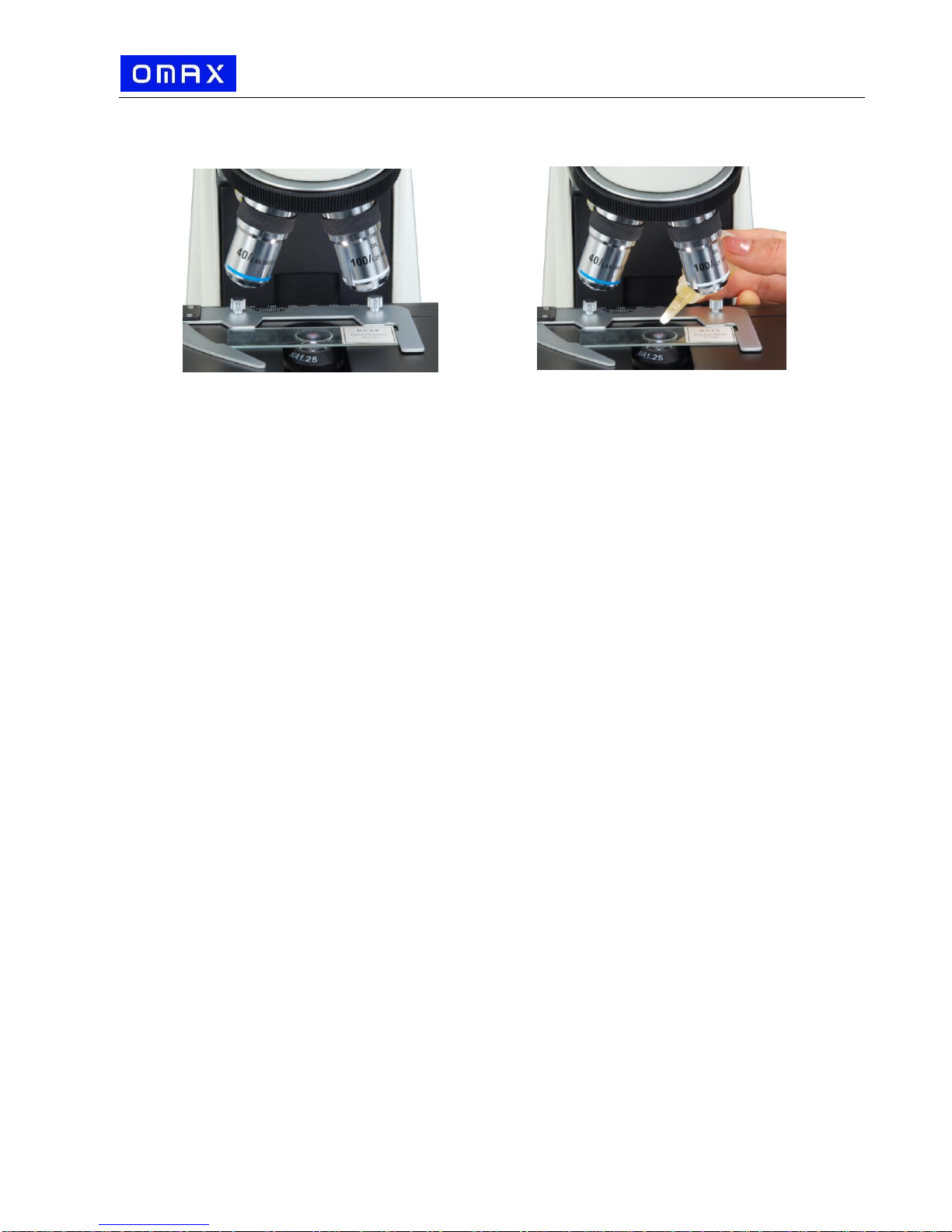
3.4 Applying the immersion oil
1) Rotate the objective nosepiece to seat the observing
position between the 40X and 100X objectives as
shown in Fig. 8 (a).
2) Place a drop of immersion oil on the slide cover as shown in Fig. 8 (b).
3) Rotate the objective nosepiece to seat the 100X objective to the observing position
until you hear a “click” sound.
4) After observing the specimen, use the lens cleaning paper to clean the 100X
objective lens gently and the specimen in time.
Stage Upward Stopper
Fig. 7

www.microscopenet.com
- 8 -
5) If it is hard to clean, you need a little bit alcohol to clean the 100X objective lens and
the specimen.
Caution (important):
When you use the 100X objective to observe the specimen, you have to finish
observing the specimen with the 4X, 10X, 40X objectives.
When you use the 100X objective to observe the specimen, you have to apply the
immersion oil on the top of the slide cover.
When you apply the immersion oil with the 100X objective, do not let the immersion
oil to contact with the dry objective lenses (especially the 40x). If the immersion oil is
on the dry objectives lens, please use the lens cleaning paper to clean the
objectives lens in time. The oil will damage the dry objective lenses.
After observing the specimen with the 100X objective, clean the 100X objective lens
first.
3.5 Adjusting condenser
1) Turn the condenser focus knob to raise or lower the condenser.
2) The condenser is raised when using high magnification objectives and lowered when
using low magnification objectives.
Note:
The centering of the condenser and the light axis of the objective are factory
adjusted. Do not attempt re-adjustment.
The highest position of the condenser has been factory adjusted. Do not attempt
re-adjustment.
3.6 Adjusting interpupillary distance
While observing with both eyes, hold the left and right eye tubes, swing inwards and
outwards. The interpupillary distance is correct when the left and right fields of view
converge completely into one image.
3.7 Adjusting eyepiece diopter
1) Using the 10X objective and your right eye only, observe your specimen through the
eyepiece and bring it into focus by adjusting the focus knobs.
2) Then observe the specimen with your left eye only through the left eyepiece. If the
specimen is not in focus, rotate the diopter ring until a sharp image is obtained.
Fig.8
Fig. 8
(b)
(a)

www.microscopenet.com
- 9 -
3.8 Adjusting Iris diaphragm
Swing the iris diaphragm lever (Fig. 9) left or right to
adjust the aperture size.
Note:
The iris diaphragm is designed to adjust the
aperture size, not to adjust the brightness although
the brightness will be changed when it's adjusted.
When aperture is adjusted to smaller size, the
contrast will be increased and the depth of field will
be increased as well. Turn up the intensity of the
light if the image is too dim.
3.9 Adjusting focus tension
The focus tension has been pre-set at the factory. If
the mechanical stage drops by itself, rotate the focus
tension ring (Fig. 10) situated between the coarse
focus knob and microscope body on the right side
until the tension is in maintained.
3.10 Camera (optional, may not included in your package)
1) Bring the microscope into focus by following the
procedures in 3.3.
2) Install the camera by following the procedures in 2.8.
3) Open image observing software to examine (more details
see camera's manual).
4) If the image is not clear, loosen the set screws (See Fig.
11) on the photo tube, turn the upper half part to lower
down or raise up the camera mounted on the top, till the
image is clear.
5) You also can capture images or record live videos through
the software, depending on the functions provided by the
software.
Note:
Please refer to the manuals in the camera’s CD for the
details of installation and operation of the camera.
3.11 Darkfield condensers observation (optional, may not included in your package)
Please see section 7 (Darkfield Condenser Installation and Operation Instructions)
3.12 Phase contrast kit observation (optional, may not included in your package)
Please see section 8 (Phase Contrast Kit Installation and Operation Instruction)
Fig.10
Fig.9
Fig.11
Iris Diaphragm Lever
Focus Tension Ring
Set Screw

www.microscopenet.com
- 10 -
4. Specifications General
Model
M834 series
Total Magnification
40X, 64X, 100X, 160X, 400X, 640X, 1000X, 1600X
Viewing Head
Trinocular, Siedentopf, inclined 30º, swiveling 360º
Swing interpupillary adjustment, 2-3/16" ~ 2-15/16" (55 ~ 75mm)
Adjustable diopter on left eyepiece tube
Photo Tube
Height adjustable
Eyepieces
1 pair of WF10X/18
1 pair of P16X
Objective Tube Length
160mm
Nosepiece
Reversed revolving quadruple
Objectives
DIN achromatic 4X, 10X, 40X (spring), 100X (spring, oil)
Condenser
Abbe, NA=1.25, w/ iris diaphragm and filter holder
Rack and pinion adjustment
Focus Mechanism
Coaxial coarse and fine focusing knobs on both sides w/ stage
upward stopper
Minimum fine focusing adjustment at 0.002mm, range 30mm
Mechanical Stage
Large double layer mechanical stage
Dimension: 5-1/2” x 4-1/4” (140mmx110mm)
Movement range: 3” x 2” (78mm X 52mm)
Cameras (optional)
Refer to the cameras specifications
Darkfield Condensers (optional)
Refer to the darkfield condensers specifications
Phase Contrast Kit (optional)
Refer to the phase contrast kit specification
Carrying Case (optional)
Net weight: 9 lbs 4.5 oz (4.25 kg)
Size: 17-1/2" x 11-1/4" x 14-1/8" (44.5cm x 28cm x 36cm)
Illumination
Transmitted: 6V/20W, halogen, variable intensity
Power Supply
AC 110V-115V, 50/60HZ (US and Canada plug)
(220V version available, contact seller)
Dimension
14-1/8” x 9-1/8” x 19” (36cm x 23cm x 48cm)
Net weight
20 lbs (9 kg)

www.microscopenet.com
- 11 -
5. Optional Parts
The optional parts may be included in some models or sold separately.)
1) Cameras
Model
Resolution
Operating System
Software
A1502
640 x 480 (0.3MP)
MS Windows
(32/64-bit)
Mac OS
Included
A1510
1280 x 1024 (1.3MP)
A1520C
1600 x 1200 (2.0MP)
A1530X
2048 x 1536 (3.0MP)
A1550X
2592 x 1944 (5.0MP)
A1590
3488 x 2616 (9.0MP)
MS Windows
(32/64-bit)
2) Darkfield Condensers
Model
Darkfield
Condenser
Numerical
Aperture
Objective
Mounting
Size(diameter)
A191
Dry
0.7-0.9
-
37mm
A191BOIL
Oil
1.36-1.25
Plan 100X/1.25 oil-0.5
160/0.17(spring), w/ iris
diaphragm
37mm

www.microscopenet.com
- 12 -
3) Phase Contrast Kits
Model
Phase Contrast Objective
Condenser
Annular Ring Plates
Centering
Telescope
A1PHB1
Plan achromatic 10X with
built-in phase plate
Plan achromatic 20X with
built-in phase plate
Plan achromatic 40X with
built-in phase plate, spring
Plan achromatic 100X with
built-in phase plate, spring,
oil
NA 1.25
five positions:
10 for 10X phase contrast
objective
20 for 20X phase contrast
objective
40 for 40X phase contrast
objective
100 for 100X phase contrast
objective
B for bright field observation,
with iris diaphragm
focusing
adjustable
A1PHB3
Achromatic 10X with built-in
phase plate
Achromatic 20X with built-in
phase plate
Achromatic 40X with built-in
phase plate, spring
Achromatic 100X with built-in
phase plate, spring, oil
five positions:
10 for 10X phase contrast
objective
20 for 20X phase contrast
objective
40 for 40X phase contrast
objective
100 for 100X phase contrast
objective
B for bright field observation,
with iris diaphragm
A1PHC1
Plan achromatic 10X with
phase plate
Plan achromatic 40X with
phase plate
three positions:
10 for 10X phase contrast
objective
40 for 40X phase contrast
objective
middle position for brightfield
observation
A1PHD
Achromatic 10X with built-in
phase plate
Achromatic 40X with built-in
phase plate, spring
Achromatic 100X with built-in
phase plate, spring, oil
10 for 10X phase contrast
objective
40 for 40X phase contrast
objective
100 for 100x phase contrast
objective

www.microscopenet.com
- 13 -
6. Troubleshooting Guide
GENERAL PROBLEMS
Problem
Cause
Solution
Lamp does not light
when switched on
No electrical power
Check power cord connection
Lamp bulb burnt out
Replace bulb
Fuse blown out
Replace fuse
Darkness at the
periphery or uneven
brightness in the field
of view
Revolving nosepiece not in click stop
position
Revolve the nosepiece to click-stop
position by swinging the objective
correctly into the optical path
The light source of the bulb is not at the
center
Adjust the position of the bulb
Dirt or dust on the
view
Dirt or dust on the eyepiece, condenser,
objective or collector lens or specimen
Clean the lens with a lens cleaning
paper
Poor image quality or
not able to get
focused image
No slide cover attached to the slide
Attach a 0.17mm slide cover
Slide cover is too thick or thin
Use a slide cover of the appropriate
thickness (0.17mm)
Slide may be upside down
(specimen at the bottom)
Turn slide over so the cover-glass faces
up
Immersion oil is on a dry objective
(especially the 40X)
Check the objectives, clean if necessary
No immersion oil used with 100X
objective
Use immersion oil
Air bubbles in immersion oil
Remove bubbles
Condenser aperture is closed or open
too much
Open or close properly
Condenser is positioned too low
Position the condenser upward
Specimen rises from stage surface
Secure the specimen in the slide holder
Blue filter not used
Use daylight blue filter
Lamp intensity is too high or low
Adjust the light intensity by rotating the
intensity control dial
Slippage of focus
when using the coarse
focusing knob Fine
focus is ineffective
Tension adjustment is set too low
Increase the tension on the focusing
knobs
Tension adjustment is set too high
Loosen the tension on the focusing
knobs

www.microscopenet.com
- 14 -
DARKFIELD PROBLEMS
Problem
Cause
Solution
It’s totally dark in
the viewing field
The light is not on
Turn on the light
(A191BOIL only) There is no oil in
between the condenser top lens
and slide
Place a drop of oil on the top lens of
condenser and let it contact the underside
of slide
(A191BOIL only) The built-in iris
diaphragm of 100X objective is not
in proper position
Adjust the iris diaphragm ring on the
objective
The condenser is not in the right
position
Lower or raise the condenser slightly to the
position that the specimen is the brightest.
(A191BOIL only) Make sure the oil contact
the bottom of the slide and the top of the
condenser during the adjustment.
The illumination is
insufficient or too
bright
The intensity of lamp is too low
Adjust the intensity dial to increase the
brightness
The condenser is not in the right
position
Lower or raise the condenser slightly to the
position that the specimen is the brightest.
(A191BOIL only) Make sure the oil contact
the bottom of the slide and the top of the
condenser during the adjustment.
The condenser is not centered
properly
Adjust the translational centering screws to
center the condenser
(A191BOIL only) The built-in iris
diaphragm of 100X objective is not
in proper position
Turn the iris diaphragm ring on the
objective
Image of the
specimen is not
clear and lacking in
sufficient contrast
The specimen is not suitable for
darkfield observation
Change to brightfield or phase contrast
(A191BOIL only) The built-in iris
diaphragm of 100X objective is not
in proper position
Turn the iris diaphragm ring on the
objective
The condenser is not in the right
position
Lower or raise the condenser slightly to the
position that the specimen is the brightest.
(A191BOIL only) Make sure the oil contact
the bottom of the slide and the top of the
condenser during the adjustment.

www.microscopenet.com
- 15 -
7. Darkfield Condenser Installation and Operation
Instructions
7.1 Dry darkfield condenser of A191
1) Mounting the dry darkfield condenser
Loosen the condenser lock thumb screw on the
condenser holder and remove the brightfield
condenser.
Install the dry darkfield condenser and tighten
the condenser lock thumb screw on the
condenser holder (see Fig. 12).
2) Centering the dry darkfield condenser
Turn the 4X objective to the light path.
Turn the condenser focus knob to lower the condenser till a dark spot showed in
the viewing field as shown in Fig. 13 (a).
Turn the condenser translational centering screws to move the dark spot to the
center as shown in Fig. 13 (b).
3) Place the slide on the stage.
4) Raise the condenser all the way to the top and
lower it a little bit.
5) Following the procedures in this manual to focus
and observe.
6) Move the condenser up or down slightly to get the
best darkfield viewing.
Note:
The dry darkfield condenser is used with the dry objectives only.
The dry darkfield condenser works with the 4X, 10X, 40X objectives.
The dry darkfield condenser won’t work with the 100X oil immersion objective.
7.2 Oil darkfield condenser of A191BOIL
1) Mounting the oil darkfield condensers
Loosen the condenser lock thumb screw on
the condenser holder and remove the
brightfield condenser.
Install the oil darkfield condensers and tighten
the condenser lock thumb screw on the
condenser holder (see Fig. 14).
2) Centering the oil darkfield condensers
Turn the 40X objective to the light path.
Turn the condenser focus knob to slowly lower
and raise the condenser till a dark spot showed in
the viewing field as shown in Fig. 15 (a).
Turn the condenser translational centering
screws to move the dark spot to the center as
shown in Fig. 15 (b).
Condenser Lock
Thumb Screw
Centering Screws
Condenser Holder
(a) (b)
(a) (b)
Fig.12
Fig.13
Fig.14
Fig.15
Condenser Lock
Thumb Screw
Centering Screws
Condenser Holder

www.microscopenet.com
- 16 -
3) Raise the condenser till the top lens is close to the opening of stage. Place a drop of
immersion oil on the top of the lens of the condenser.
4) Place the slide on the stage. Raise the condenser and let the oil
drop contact the bottom of the slide. If air bubbles exist in the oil,
clean the oil from the condenser lens and bottom of slide with a
camera cleaning paper and repeat the procedures.
5) Follow the procedures in this manual to bring the sample on slide
in focus and observe.
6) When using the 100X oil darkfield objective, you will need to drop
the immersion oil and adjust the iris ring (Fig. 16) to get proper
brightness and contrast of view field.
Note:
The condenser won’t work well if no oil drop applied on the condenser.
8. Phase Contrast Kit Installation and Operation
Instructions
8.1 Phase contrast kits of A1PHB1 or A1PHB3:
1) Mounting the phase contrast objectives
a. Take off all the objectives from the nosepiece.
b. Install the phase contrast objectives onto the nosepiece following the steps in
2.4.
2) Mounting the phase contrast condenser/annular ring disk
a. Rotate the nosepiece and set the 4X objective in position.
b. Turn the coarse focus knob to raise the mechanical stage to the highest position
without contacting the 4X objective.
c. Turn the condenser control knob to raise the condenser to the highest position.
d. Loosen the condenser lock thumb screw, pull down the condenser and take it off.
e. Insert the condenser/annular ring disk into the condenser holder, and tighten the
thumb screw.
f. Re-adjust the condenser height to its normal position.
g. Re-adjust the mechanical stage height to its
normal position.
Note:
When raising the mechanical stage, do not
make contact with the objective.
3) Turn the desired objective into light path.
4) Turn the annular ring disk to put the
corresponding ring into light path, i.e. if you are
using the 20X phase contrast objective, you
should turn the disk at 20 as shown in Fig. 17.
Fig.16
Iris Ring
20
Fig.17

www.microscopenet.com
- 17 -
(a) (b)
(c) (d)
5) Centering the annular ring.
a. Remove one eyepiece from the microscope
eyepiece tube and insert the centering telescope as
shown in Fig. 18.
b. Observe from the telescope. The bright ring and
dark ring should be coincided with each other as
shown in Fig.19 (d).
c. If the ring images are not clear, turn the top of
telescope until both ring images are in focus.
d. If the bright ring is still obscure as in Fig.19 (b),
adjust the condenser focus knob.
e. If the two ring images are not coincided as shown
in Fig.19 (c), hold the ring plate from the bottom of
the annular ring disk and adjust its position until
two ring images are coincided.
f. Remove the centering telescope and replace it with
the eyepiece.
g. Put the specimen on the stage and adjust the
illumination, focusing, etc following the instructions
in this manual.
Note:
The phase contrast condenser will be working as
a conventional Abbe condenser if the annular ring disk being put at B position.
8.2 Phase contrast kit of A1PHC1:
1) Mounting the phase contrast kit
a. Replace the bright field objective(s) on nosepiece with the phase contrast
objective(s).
b. Rotate the nosepiece and set the 4X objective in position.
c. Turn the coarse focus knob to raise the mechanical stage to the highest position
without contacting the 4X objective.
d. Turn the condenser control knob to raise the condenser to the highest position.
e. Loosen the condenser lock thumb screw (Fig. 20), pull down the condenser and
take it off.
f. Insert the condenser/annular ring disk into the condenser holder, and tighten the
thumb screw (Fig. 20).
g. Re-adjust the condenser height to its normal position.
h. Re-adjust the mechanical stage height to its normal position.
Fig.19
Fig.20
Condenser Holder
Condenser Lock Thumb Screw
Fig.18

www.microscopenet.com
- 18 -
Condenser Holder
Condenser Lock Thumb Screw
Note: there are 2 phase contrast objectives: 10X and 40X, and there are 2
condenser annular rings on the annular ring switch: 10X and 40X. The
corresponding objective and annular ring must work together, i.e. 10X phase
contrast objective must work with 10X condenser annular ring, and so on.
2) Centering the condenser ring plate
a. Connect the power cord to the microscope and insert the plug into a power outlet.
b. Turn the desired phase contrast objective into
light path. Slide the annular ring switch to the
required annular ring corresponding to the phase
contrast objective in the light path.
c. Remove one eyepiece from the microscope
eyepiece tube and insert the centering telescope.
d. Observe from the telescope. The bright ring and
dark ring should be coincided with each other as
shown in Fig. 21 (d).
e. If the ring images are not clear, turn the top of
telescope until both ring images are in focus.
f. If the bright ring is still obscure as in Fig. 21 (b),
adjust the condenser focusing knob.
g. If the two ring images are not coincided as shown
in Fig. 21 (c), adjust the two centering screws on
the phase contrast condenser.
h. Remove the centering telescope and replace the eyepiece.
8.3 Phase contrast kit of A1PHD:
1) Mounting the phase contrast kit
a. Replace the bright field objective(s) on nosepiece with
the phase contrast objective(s)
b. Thread the condenser ring plate onto the condenser as
shown in Fig.22.
c. Loosen the condenser lock thumb screw as shown in
Fig. 23; take off the original condenser from the holder.
d. Insert the phase contrast condenser into the condenser
holder as shown in Fig. 23; tighten the condenser lock
thumb screw.
Fig. 23
Fig.22
(b) (b)
(c) (d)
Fig. 21
Fig.22
This manual suits for next models
2
Table of contents
Other Omax Microscope manuals