FIOR & GENTZ NEURO VARIO-SPRING User manual
Systemknöchelgelenk
System Ankle Joint
Druckdatum: 2018-09
Der Inhalt dieser Produktbeilage wird regelmäßig aktualisiert und ist beim Einsatz des Produktes unbedingt zu beachten.
Sie finden diese Produktbeilage auch im Download-Bereich unserer Website unter www.fior-gentz.de/downloads. Seite 2
Date printed: 2018-09
This manual is regularly updated and should be strictly followed.
You can also find this manual in the download section on our website at www.fior-gentz.com/downloads. Page 16
DE
GB

16
Content Page
GB
1. Declaration of Conformity 17
2. Warranty 17
3. Safety Information 17
4. Safety Instructions 17
4.1 Classification of the Safety Instructions 17
4.2 All Instructions for a Safe Handling of the NEURO VARIO-SPRING System Ankle Joint 18
5. Application 20
6. Joint Function 20
7. Scope of Delivery 20
8. Load Capacity 20
9. Tools for Assembling the System Joint 21
10. Assembly/Lamination Dummies 21
11. Assembly Instructions 21
11.1 Mounting the Functional Unit 22
11.2 Mounting the System Stirrup 22
11.3 Mounting the Cover Plate 22
11.4 Checking the System Joint's Free Movement 23
11.5 Basic Alignment 23
11.6 Securing the Screws 23
12. Adjustment Options on the Orthosis 24
12.1 Adjustable Alignment 24
12.2 Adjustable Range of Motion 24
12.2.1 Filing the Range of Motion 24
12.2.2 Fine Adjusting the Range of Motion 24
12.2.3 Securing the Adjusting Screw 24
12.3 Reading Joint Angles 25
13. Converting the NEURO VARIO-SPRING into a NEURO VARIO-CLASSIC
System Ankle Joint 25
14. Advice on Production Techniques 25
14.1 Parallel Alignment of System Joints 26
14.2 Mounting to the System Side Bar/System Anchor 26
15. Maintenance 26
15.1 Repairing the Bearing Nut Bore 26
15.2 Replacing the Sliding Washers 27
15.3 Cleaning 27
16. Disposal 27
17. Spare Parts 28
18. Accessory Parts 29
19. Information for the Treatment Documentation 31
17
1. Declaration of Conformity
We declare that our medical devices as well as our accessories for medical devices are in conformity with the
requirements of the Medical Devices Directive 93/42/EEC. Therefore, the FIOR &GENTZ products bear the CE marking.
2. Warranty
The warranty only applies if the product is used under the described conditions and for the intended purpose.
The warranty expires if the product is used differently, if it is combined with other components or materials or
if it is mounted according to a different production technique than the one recommended by the FIOR &GENTZ
Orthosis Configurator. A combination with products from other manufacturers requires a written consent by the
seller. The warranty and guarantee expire if the product is mounted several times. For further information, we
refer to our General Terms and Conditions of Business Transactions, Sales, Delivery and Payment.
3. Safety Information
This manual is addressed to orthotists. That is why the content basically confines to features of the product. It
does not contain any notes about dangers which are obvious to orthotists. Please note that the product is not
supposed to be combined with other components or materials than with those recommended by the FIOR& GENTZ
Orthosis Configurator.
To achieve maximum safety, please show the patient and/or the care team how to use and maintain the product
correctly. Enclosed to this manual you will find a patient information which has to be given to the patient and/
or the care team.
For information reasons and for the safety of your patient, please note all information provided in this manual
including notes, tables and illustrations. In particular, note the safety instructions indicated by DANGER, WARNING,
CAUTION and NOTICE that are listed and explained in the following paragraph. Ignoring this information may
lead to patient injuries and property damage.
4. Safety Instructions
4.1 Classification of the Safety Instructions
DANGER Important information about a possible dangerous situation which,
if not avoided, leads to death or irreversible injuries.
WARNING
Important information about a possible dangerous situation which,
if not avoided, leads to reversible injuries that need medical treatment.
CAUTION
Important information about a possible dangerous situation which,
if not avoided, leads to light injuries that do not need medical treatment.
NOTICE
Important information about a possible situation which,
if not avoided, leads to damage of the product.
All serious incidents connected to the product shall be reported to the manufacturer or the responsible
authorities.
18
4.2 All Instructions for a Safe Handling of the NEURO VARIO-SPRING System Ankle Joint
DANGER
Potential Trac Accident Due to Limited Driving Ability
Advise the patient to gather information about all safety and security issues before driving
a motor vehicle with orthosis. The patient should be able to drive a motor vehicle safely.
WARNING
Risk of Falling Due to Improper Handling
Inform the patient about the correct use of the system joint and potential dangers especially
with regards to:
- moisture and water as well as
- excessive mechanical stress (e.g. due to sports, increased activity or weight gain).
WARNING
Risk of Falling Due to Loosely Attached Cover Plate
Mount the cover plate to the system joint according to the assembly instructions in this
manual. Secure the screws with the specified torque and the corresponding adhesive and
make sure that no sliding washers are damaged in the process.
WARNING
Risk of Falling Due to Permanent Higher Load
If patient data has changed (for example, due to weight gain, growth or increased activity),
recalculate the load capacity of the system joint. For this purpose, use the Orthosis Configurator
or contact Technical Support.
WARNING
Risk of Falling Due to Improper Shoe
Advise the patient to wear a shoe to which the orthosis is adjusted in order to avoid joint
dysfunction.
WARNING
Risk of Falling Due to Incorrectly Adjusted Adjusting Screw
Adjust the adjusting screw according to the information in this manual. Do not make a fine
adjustment of more than 10° and secure the adjusting screw with the securing pin and the
corresponding adhesive.
WARNING
Damage to the Anatomical Joint Due to Incorrect Position of the Joint’s Mechanical Pivot
Point
Determine the mechanical pivot points correctly in order to avoid a permanent incorrect
load on the anatomical joint. Please refer to the online tutorials on our website or contact
Technical Support.

19
WARNING
Jeopardising the Therapy Goal Due to Lack of Free Movement
Check if the system joint moves freely in order to avoid restrictions of the joint function.
Use suitable sliding washers according to the information in this manual.
WARNING
Jeopardising the Therapy Goal Due to Incorrectly Filed System Stirrup
Do not file the system stirrup too far. This applies especially to the dorsiflexion stop, otherwise
the forefoot lever is not activated. As a result, the patient is only stabilised insuciently by the
orthosis and the gait worsens. In order to avoid this, always file the system stirrup:
- gradually into the required stop angles and
- only so far that no more than a 10° fine adjustment is possible.
NOTICE
Limitation of the Joint Function Due to Improper Processing
Errors in processing can impair the joint function. Pay particular attention to:
- correctly connecting the system side bar/system anchor with the system case in accordance
with the production technique;
- greasing the joint components only slightly and
- adhering to the maintenance intervals.

20
5. Application
The NEURO VARIO-SPRING system ankle joint is exclusively for use for orthotic fittings of the lower extremity.
It must be handled by a professionally trained user. You will find more information about this product under
paragraph 6 Joint Function.
Every mechanical joint influences the orthosis' function and thus also the function of the leg. All FIOR &GENTZ
system joints were developed for everyday life activities such as standing, walking and running but not for
extreme loads due to sports such as climbing and parachuting.
Depending on the type of orthotic fittings and the patient’s individual physical abilities, driving a motor vehicle
safely should be guaranteed. This is subject to national laws and checked by authorised medical bodies. It is
recommended to modify the motor vehicle to the patient’s special needs (e.g. automatic transmission) so that
the driving ability is given even without a functioning orthosis.
6. Joint Function
The basic function of the NEURO VARIO-SPRING system ankle joint s to provide motion control with a dorsi-
flexion assist. The range of motion in dorsiflexion can be adjusted by filing the system stirrups and additionally
by using the adjusting screws. The dorsiflexion-assist effect can be changed by replacing the functional unit or
the pin and pressure spring.
7. Scope of Delivery
The scope of delivery includes the following articles:
Description Quantity
NEURO VARIO-SPRING system ankle joint (fig. 1) 1
securing pin (fig. 2) 1
AGOMET F330, 5g (fig. 3) 1
orthosis joint grease, 3g (fig. 4) 1
assembly/lamination dummy (fig. 5) 1
Corresponding system stirrups in different designs and for different production techniques have to be ordered
separately.
8. Load Capacity
You can find all relevant patient data for your selected system joint in the configuration you performed with the
Orthosis Configurator and/or on your completed orthotic treatment sheet.
fig. 1
fig. 3 fig. 4 fig. 5
fig. 2
21
9. Tools for Assembling the System Joint
Tools
System Width
14mm 16mm 20mm
T20 hexalobular screwdriver
as well as T20 hexalobular bit xxx
screwdriver for slotted screws with the blade size 3.5 x 0.6mm x x x
torque screwdriver 1-6Nm x x x
pin punch x x x
assembly aid for cover plate - x x
10. Assembly/Lamination Dummies
Assembly/lamination dummies are included in the scope of delivery of the system joint. You can find the article
numbers as well as the corresponding tools for the parallel alignment in our product catalogue System Joints
and Articulated System Side Bars.
11. Assembly Instructions
The system joint is delivered fully assembled (fig. 7). All functions are checked beforehand.
You have to disassemble the system joint for mounting it in the orthosis and for mainte-
nance. When disassembling the system joint, make sure not to interchange the different
parts with each other or with parts of other system joints. Clean all system components.
In order to clean the threads in the cover plate, use the Super Clean LOCTITE7063
(articleno.: WZ7063) to remove any insulating wax residues. To ensure optimum func-
tionality, please follow the assembly instructions below:
fig. 7
fig. 6

22
11.1 Mounting the Functional Unit
Start the assembly of the NEURO VARIO-SPRING system ankle joint by mounting the
functional unit. Proceed as follows:
1. Assemble the functional unit consisting of ball (1), pin (2) and pressure spring (3) in
the correct order (fig. 8).
2. Screw in the pressure screw (4) tightly in order to secure the functional unit in the
cover plate's spring duct.
11.2 Mounting the System Stirrup
Mount the system stirrup corresponding to the system width and production technique
to the NEURO VARIO-SPRING system ankle joint. Proceed as follows:
1.
Grease the axle bore of the system stirrup as well as the friction
surfaces of the bearing nut and the first sliding washer with the
delivered orthosis joint grease.
2. Put the bearing nut into the intended opening of the joint's upper
part. The bearing nut has to be placed completely into the opening.
- correct position of the bearing nut (fig. 9);
- incorrect position of the bearing nut (fig. 10).
3. Place the first sliding washer slightly greased on both sides onto the
joint's upper part (fig. 11).
4. Mount the system stirrup (fig. 12).
11.3 Mounting the Cover Plate
Then, mount the cover plate of the NEURO VARIO-SPRING system
ankle joint. Proceed as follows:
1. Clamp the assembly aid for cover plate into a vice.
2. Place the cover plate with the ball on the pin of the assembly aid for
cover plate and compress the pressure spring by pulling the cover
plate in your direction until the cover plate fits into the assembly aid
for cover plate.
3.
Remove the assembly aid for cover plate with the cover plate from
the vice (fig. 13).
4.
Apply spray adhesive on one side of the second sliding washer and adhere it to the cover plate (fig. 14). Grease
the other side of the sliding washer slightly with the delivered orthosis joint grease.
fig. 11 fig. 12
fig. 13
fig. 8
4
3
2
1
fig. 9 fig. 10
The assembly aid for cover plate can only be used for a NEUROVARIO-SPRING system ankle joint with
a system width of 16mm or 20mm. A NEURO VARIO-SPRING system ankle joint with a system width
of 14mm can be mounted effortlessly without the assembly aid.
fig. 14

23
Place the sliding washer in a way that prevents it from being damaged
when mounting the cover plate. If you have nevertheless placed the
sliding washer incorrectly (fig.15-16), remove the particles and place a
new sliding washer.
5.
Mount the cover plate using the assembly aid for cover plate by plac-
ing it sideways on the system stirrup (fig.17).
6.
Screw in the first countersunk flat head screw (axle screw, S1; fig.18)
according to the torque given in the table (see paragraph 11.6).
7. Now, screw in the second countersunk flat head screw (S2; fig. 19)
according to the torque given in the table (see paragraph 11.6).
8.
Remove the assembly aid for cover plate from the mounted cover plate
by grasping the assembly aid for cover plate at the top and carefully
pulling it up and then sideways from the functional unit.
11.4 Checking the System Joint's Free Movement
Check if the system joint moves freely. If the system joint runs with lateral
play, mount the next thicker sliding washer. If it does not move freely
(it is jammed), mount the next thinner sliding washer. For more informa-
tion about the sliding washers see paragraph 15.2.
11.5 Basic Alignment
When mounting the system ankle joint, mind the correct adjustment of the dorsiflexion stop as it is decisive for
the entire alignment of the orthosis. Correct the dorsiflexion stop, if necessary.
11.6 Securing the Screws
After the orthosis has been produced and tried on and before it is given to the patient, secure the screws for the
cover plate with a torque which corresponds to the system width (see table and cover plate of the system joint) and
LOCTITE 243 medium strength (article no.: KL2000). Let the adhesive harden (final strength after approx. 24 hours).
Position of the Screw (Fig. 19)
System Width
14mm 16mm 20mm
S1 (screw 1, axle screw) 4Nm 4Nm 4Nm
S2 (screw 2) 4Nm 4Nm 4Nm
fig. 16fig. 15
Jammed sliding washer particles cause lateral play in the system
joint and a damaged sliding washer could lead to restrictions of
the joint function.
The screws of the cover plate are not secured with the necessary torque at delivery.
fig. 18
fig. 17
fig. 19
S2
S1

24
12. Adjustment Options on the Orthosis
The NEURO VARIO-SPRING system ankle joint can be individually adjusted to the
patient's pathological gait with the help of two adjustment possibilities (fig. 20).
12.1 Adjustable Alignment
When producing an orthosis with the NEURO VARIO-SPRING system ankle joint,
the alignment of the orthosis has to be adjusted to the patient's pathological gait
using the adjusting screw (fig.20). Furthermore, changes in the pathological gait
can be treated flexibly. The position of the adjusting screw cannot change due to
a securing pin installed in the system joint (see paragraph 12.2.3).
12.2 Adjustable Range of Motion
The range of motion is the angle of rotation between two defined limita-
tions of movement.
12.2.1 Filing the Range of Motion
The range of motion of the system ankle joint in dorsiflexion can be
adjusted by filing. For this purpose, the system stirrup is marked with
lines which serve as orientation (fig.21). If the system stirrup is filed to
20°, the system joint becomes free moving in dorsiflexion.
12.2.2 Fine Adjusting the Range of Motion
The range of motion is roughly adjusted by filing the system stirrup. Use the adjusting screw of the system joint
to fine adjust the range of motion at a maximum of 10 more degrees (fig. 20). When screwing in the adjusting
screw too much (more than 10° fine adjusting), the surface pressure between adjusting screw and system stirrup
can become so high that the screw is compressed and loses its function.
12.2.3 Securing the Adjusting Screw
When the adjusting screw turns or loosens, it must be secured again with
the securing pin. Please follow the assembly instructions below:
1. Unscrew the adjusting screw out of the thread (fig. 20).
2. Demount the cover plate and drive out the premounted securing pin
with a pin punch (fig. 22).
3. Turn the worn position of the securing pin by about 90° (fig. 23) and
put it in again (fig. 24).
4. Mount the cover plate (fig. 25).
5. Now, screw the adjusting screw into the desired position (fig. 25).
fig. 20
15°
20°
10°
2°
4°
6°
8°
fig. 21
For more detailed information about the adjustment of the range of motion please refer to the
publications in the download section on our website at www.fior-gentz.com/downloads.
fig. 22 fig. 23
fig. 24 fig. 25
90°

25
6. Additionally, secure the adjusting screw with LOCTITE 243 (article no.:KL2000). Let the adhesive harden
(final strength after approx. 24 hours).
12.3 Reading Joint Angles
The lasered degree markings on the system stirrup and the lasered line
on the cover plate (fig.26) show the angle of the system joint towards
the system stirrup. When handing over the orthosis, you can check the
individual normal posture (the orthosis' basic alignment) by the markings.
You can read as well as record the joint angle indicated at this time. By
doing so, you can easily compare later adaptations or deviations of the
individual normal posture with your documentation.
The distances between the degree markings for each system width can
be seen in the following table.
Degree Marking
System Width 14mm 16mm 20mm
Degree 2° 2° 2°
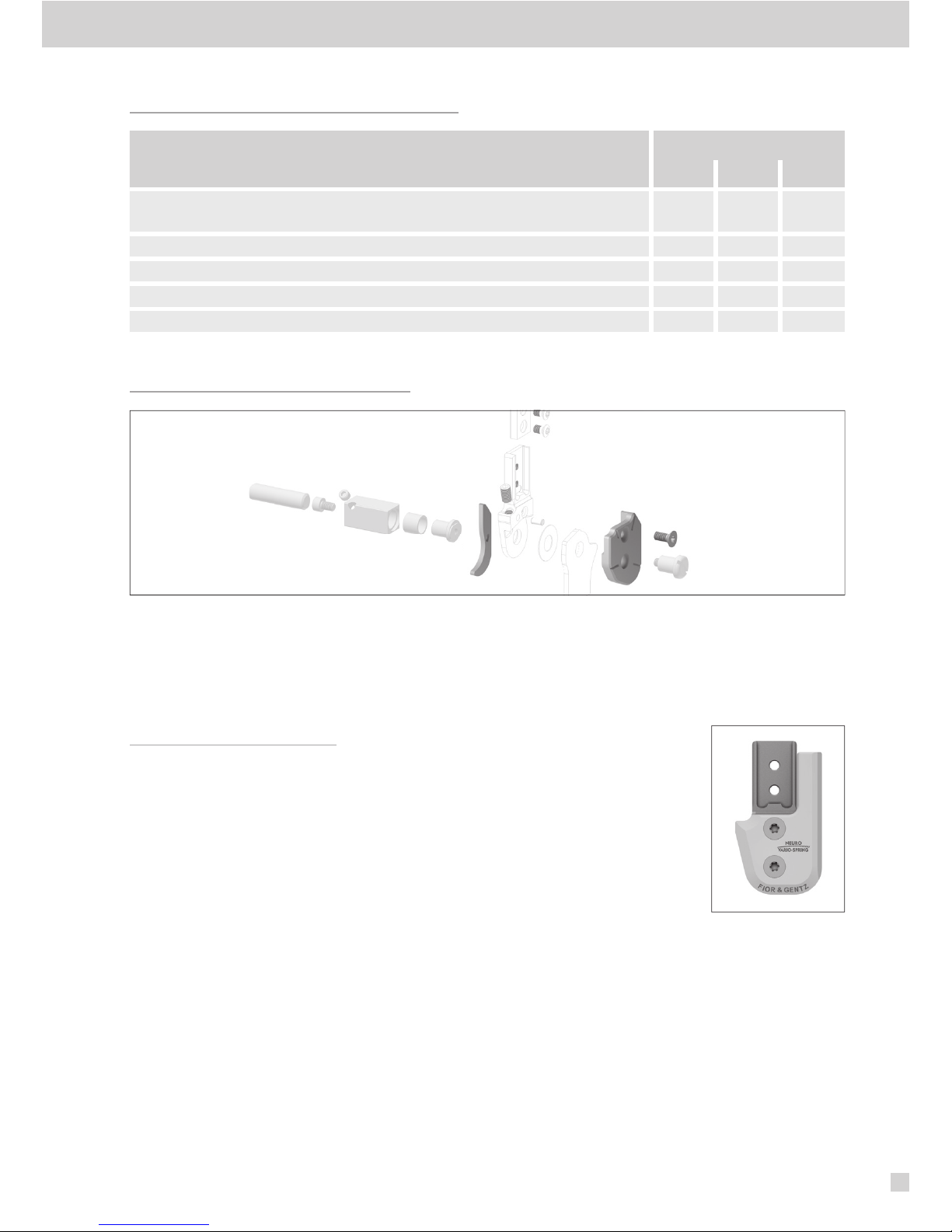
13.
Converting the NEURO VARIO-SPRING into a NEURO VARIO-CLASSIC System Ankle Joint
You can convert the system joint in order to use the orthosis without dor-
siflexion assist. The joints' upper parts of the NEURO VARIO-SPRING and
NEURO VARIO-CLASSIC system ankle joints are identical in construction.
Disassemble the functional unit of the NEURO VARIO-SPRING system
ankle joint and mount the cover plate of the NEURO VARIO-CLASSIC
system ankle joint (fig.27). When ordering the cover plate, note and
respect the corresponding system width.
14. Advice on Production Techniques
Use the system components determined by the Orthosis Configurator when
producing an orthosis and mind the recommended production technique.
If the securing pin is deformed after the driving, put in a new one (article no.:GS4007). If
necessary, cut the new pin with a sharp knife so that it does not protrude. An additional security
pin is included in the delivery.
fig. 26
You will find more information about the individual normal posture on the internet at
www.fior-gentz.com.
You will find detailed information about our production techniques in the section “Orthosis Production”
under “Online Tutorials” and “Producing the Orthosis” on our website www.fior-gentz.com.
fig. 27
26
14.1 Parallel Alignment of System Joints
You will find the necessary tools for the parallel alignment of the system joints on the positive cast in our latest
product catalogue System Joints and Articulated System Side Bars.
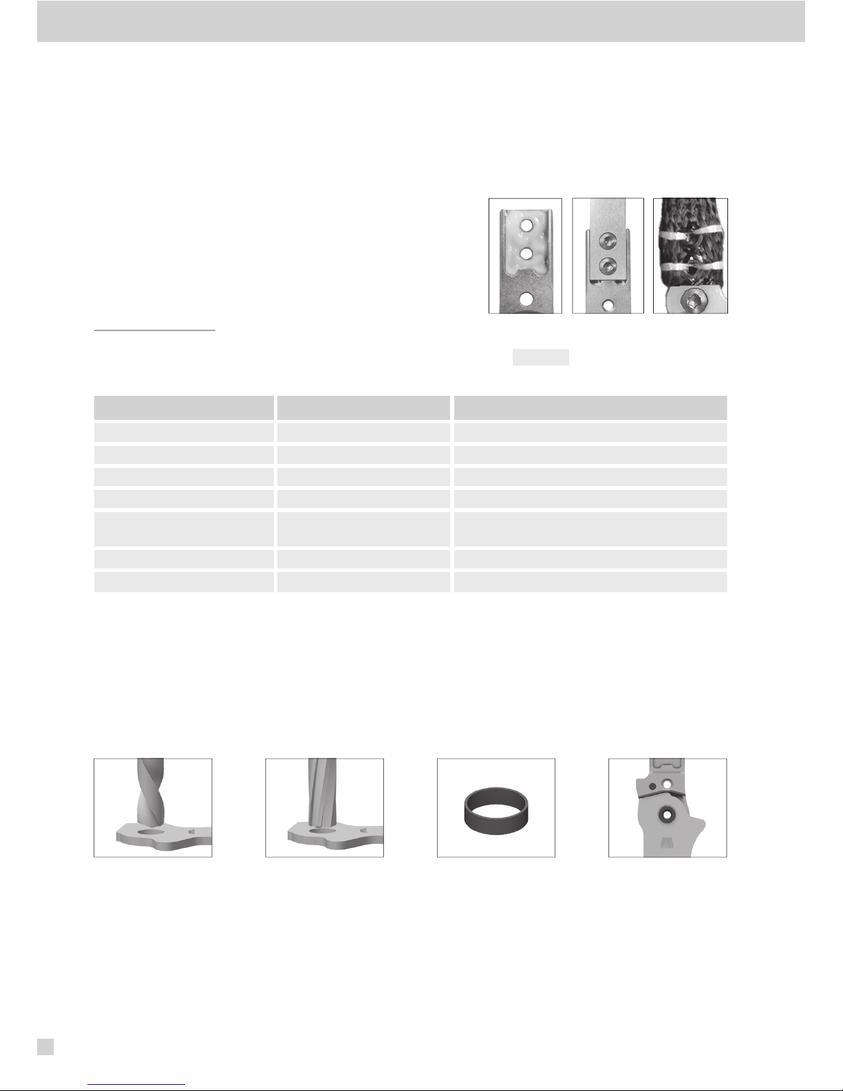
14.2 Mounting to the System Side Bar/System Anchor
Depending on the production technique, the system side bar/system
anchor must be adhered and screwed or sewed together with the
system joint (fig.28-30). You will find further information concerning
the different production techniques on the internet or in the manual
System Side Bars and System Anchors (article no.: PB1000-SA).
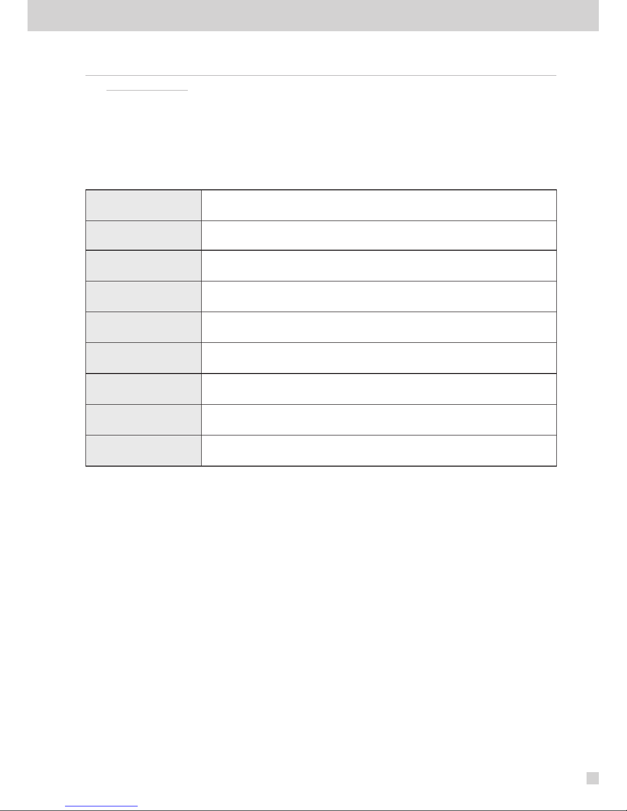
15. Maintenance
We recommend checking the system joint’s functionality and wear every 6 months.
Check the following parts in particular:
Joint Part Problem Measure
pressure spring fatigue of spring force replacing
pin wear replacing
bearing nut wear replacing
securing pin wear replacing, see paragraph 12.2.3
bore for bearing nut of
system stirrup oversize inserting repair bushing,
see paragraph 15.1
sliding washers wear replacing, see paragraph15.2
adjusting screw wear replacing
15.1 Repairing the Bearing Nut Bore
If the bore for the bearing nut is worn out at the system stirrup, bore (fig.31) and ream (fig.32) it with a reamer
(see product catalogue System Joints and Articulated System Side Bars) in order to insert a repair bushing
(boring and reaming measurements see table). For a centred boring and reaming, clamp the system stirrup firmly.
After inserting the repair bushing made of bronze (fig. 33), the bore has the specified size again. The joint system
is now free of play (fig.34).
fig. 34fig. 33fig. 32fig. 31
fig. 29
fig. 28 fig. 30

27
Boring and Reaming Measurements [mm]
System
Width
Bearing Nut
Outer Ø
Repair
Bushing
Inner Ø
Repair
Bushing
Outer Ø
Ø
Measurement
for Boring
Ø
Measurement
for Reaming
Art. No.
Repair Bushing
14mm 8.5 8.5 9.6 9.3 9.6 H7 BR1009-L025
16mm 9.6 9.6 10.5 10.2 10.5 H7
BR1110-L030
20mm 10.5 10.5 11.5 11.2 11.5 H7
BR1211-L030
15.2 Replacing the Sliding Washers
If the premounted sliding washers wear out, they have to be replaced by new ones with the same thickness. The
article numbers of the premounted sliding washers are on the back page of this manual. The last three digits of
the article number stand for the thickness of the sliding washer, e.g. GS1407-040. The thickness of this sliding
washer is 0.40mm. In total, the sliding washers are available in five dierent thicknesses. The thickness of a sliding
washer is indicated by the markings. For example, a sliding washer with two grooves is 0.40mm thick, whereas a
sliding washer with one notch is 0.55mm thick (fig.35). Note and respect that when reordering.
15.3 Cleaning
While using the orthosis, the system joint has to be cleaned if needed and during regularly carried out mainte-
nance. For this purpose, disassemble the system joint and clean the soiled system components with a dry cloth.
16. Disposal
Dispose of the system joint and its individual parts properly. The product must not be disposed
of with the residual waste (fig.36). Please comply with the applicable national laws and
local regulations for the proper recycling of recyclable materials.
0.45mm 0.50mm 0.55mm 0.60mm
0.40mm
fig. 35
fig. 36
For proper disposal, it is necessary to demount the system joint from the orthosis.
28
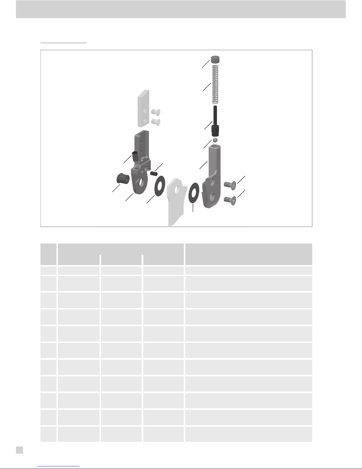
17. Spare Parts
Item
Article Number for System Width
Description
14mm 16mm 20mm
1 SB8559-L0620 SB9669-L0760 SB1069-L0810 bearing nut
2 SF0412-L/ST SF0413-L/ST SF0415-L/ST upper part, left lateral or right medial, straight,
steel (with adjusting screw)
2 SF0412-R/ST SF0413-R/ST SF0415-R/ST upper part, left medial or right lateral, straight,
steel (with adjusting screw)
2 SF0412-L/TI SF0413-L/TI SF0415-L/TI upper part, left lateral or right medial, straight,
titanium (with adjusting screw)
2 SF0412-R/TI SF0413-R/TI SF0415-R/TI upper part, left medial or right lateral, straight,
titanium (with adjusting screw)
2 SF0432-L/ST SF0433-L/ST SF0435-L/ST upper part, left lateral or right medial, bent
inwards, steel (with adjusting screw)
2 SF0432-R/ST SF0433-R/ST SF0435-R/ST upper part, left medial or right lateral, bent
inwards, steel (with adjusting screw)
2 SF0432-L/TI SF0433-L/TI SF0435-L/TI upper part, left lateral or right medial, bent
inwards, titanium (with adjusting screw)
2 SF0432-R/TI SF0433-R/TI SF0435-R/TI upper part, left medial or right lateral, bent
inwards, titanium (with adjusting screw)
2 SF0432-8L/ST SF0433-8L/ST SF0435-8L/ST upper part, left lateral or right medial, bent
outwards, steel (with adjusting screw)
2 SF0432-8R/ST SF0433-8R/ST SF0435-8R/ST upper part, left medial or right lateral, bent
outwards, steel (with adjusting screw)
1
24
10
11
9
3
8
7
6
5
2a
4
fig. 37

29
Item
Article Number for System Width
Description
14mm 16mm 20mm
2 SF0432-8L/TI SF0433-8L/TI SF0435-8L/TI upper part, left lateral or right medial, bent
outwards, titanium (with adjusting screw)
2 SF0432-8R/TI SF0433-8R/TI SF0435-8R/TI upper part, left medial or right lateral, bent
outwards, titanium (with adjusting screw)
2a SC9605-L08ST SC9606-L10ST SC9606-L10ST adjusting screw
3 GS4007 GS4007 GS4007 securing pin
4 GS2009-* GS2210-* GS2611-* sliding washer*
5 SC2108-L04 SC2109-L05 SC2110-L05 pressure screw
6 FE1634-02 FE2836-02 FE2752-02 pressure spring, golden
7 SF0342-75 SF0343-72 SF0345-81 pin
8 KU1005-ST KU1005-ST KU1005-ST ball
9 SF0462-L/AL SF0463-L/AL SF0465-L/AL cover plate, left lateral or right medial
9 SF0462-R/AL SF0463-R/AL SF0465-R/AL cover plate, left medial or right lateral
10 SC1405-L10 SC1405-L11 SC1405-L12 countersunk flat head screw, hexalobular socket
11 SC1405-L10 SC1405-L11 SC1406-L12 countersunk flat head screw, hexalobular socket
(axle screw)
5-11 SF4972-L/AL SF4973-L/AL SF4975-L/AL functional unit NEURO VARIO-SPRING, left
lateral or right medial
5-11 SF4972-R/AL SF4973-R/AL SF4975-R/AL functional unit NEURO VARIO-SPRING, left
medial or right lateral
* Sliding Washers
Article Number for System Width
14mm 16mm 20mm
Ø = 20mm Ø = 22mm Ø = 26mm
GS2009-040 GS2210-040 GS2611-040
GS2009-045 GS2210-045 GS2611-045
GS2009-050 GS2210-050 GS2611-050
GS2009-055 GS2210-055 GS2611-055
GS2009-060 GS2210-060 GS2611-060
18. Accessory Parts
You will find a big variety of accessory parts in our latest product catalogue System Joints and Articulated
System Side Bars.
When reordering, note and respect the thickness of the sliding washers (explanation see paragraph15.2).
31
19.
Informationen für die Versorgungsdokumentation/Information for the Treatment
Documentation
Bitte heften Sie diese Produktbeilage zu Ihrer Versorgungsdokumentation!
Add this manual to your treatment documentation!
Patientendaten/Patient´s Data
Name
Name
Straße
Address
PLZ, Wohnort
Postcode, City
Telefon privat
Home Telephone
Telefon geschäftlich
Telephone at Work
Kostenträger
Insurance
Mitgliedsnummer
Insurance No.
Behandelnder Arzt
Attending Physician
Diagnose
Diagnosis
Die Angaben der Produktbeilage beziehen sich auf den aktuellen Stand bei Drucklegung. Produktangaben sind
Richtwerte. Technische Änderungen vorbehalten.
Alle Urheberrechte, besonders die Rechte der Verbreitung, Vervielfältigung und Übersetzung, bleiben ausschließlich
der FIOR &GENTZ Gesellschaft für Entwicklung und Vertrieb von orthopädietechnischen Systemen mbH vorbehalten.
Nachdrucke, Kopien sowie sonstige Vervielfältigungen elektronischer Art dürfen auch auszugsweise nicht ohne
schriftliche Genehmigung der FIOR &GENTZ Gesellschaft für Entwicklung und Vertrieb von orthopädietechnischen
Systemen mbH vorgenommen werden.
The information in this manual is valid at the date of printing. The contained product information serves as a guideline. Subject
to technical modifications.
All rights, particularly the distribution, copy and translation of this manual or any part of it, in paper or as electronic document,
must be authorised in writing by FIOR &GENTZ Gesellschaft für Entwicklung und Vertrieb von orthopädietechnischen Systemen
mbH. Reprints, copies and any other electronic reproduction, even partial, must be authorised in writing by FIOR &GENTZ
Gesellschaft für Entwicklung und Vertrieb von orthopädietechnischen Systemen mbH.

PB4000-SF-09/2018
Montierte Gleitscheiben-Version
Mounted Sliding Washer Version
1. GS ____________ - ________
2. GS ____________ - ________
Beinseite
Leg Side
links/left rechts/right
Der Qualitätsstandard der Firma FIOR & GENTZ ist durch eine unabhängige Zertifizierungsgesellschaft
nach den internationalen Normen ISO 9001 und ISO 13485 geprüft und bescheinigt worden.
The quality standard of the FIOR & GENTZ company has been controlled and certified by an independent certification
organisation according to the international standards ISO 9001 and ISO 13485.
Gesellschaft für Entwicklung und Vertrieb
von orthopädietechnischen Systemen mbH
Dorette-von-Stern-Straße 5
21337 Lüneburg (Germany)
info@fior-gentz.de
www.fior-gentz.com
+49 4131 24445-0
+49 4131 24445-57
Table of contents
Popular Power Tools manuals by other brands


Milwaukee
Milwaukee M12 AL-0 Original instructions

SCHUNK
SCHUNK KSO 65 Installation and operating instruction

Ribimex
Ribimex PRS499 quick start guide

EINHELL
EINHELL TE-MS 18/210 Li Original operating instructions

AutoTeks
AutoTeks BUILDEX Operator's manual and maintenance instructions

Geo Knight
Geo Knight Digital DK20 16x20 manual


