GEZE GC 334 User manual

GEZE GmbH / Reinhold-Vöster-Straße 21-29 / 71229 Leonberg / Germany / Tel. ++49(0)7152-203-0 / Fax ++49(0)7152-203-310
Mat.-Nr. 126833 Änd.-St. 03 Zeichn.-Nr. 70710-9-9508 Printed in Germany Änderungen vorbehalten
2
1
4
5
1
1
3
1
1
2
1
2
1
2
1
1
1
2
1
2
3
1
3
2
4
2
©GEZE | Originalbedienungsanleitung | 47.0167 / V1 - 05.17
Hiermit erklärt GEZE, dass sich der GC 334 in Übereinstimmung mit den grundlegenden Anforderungen und den übrigen einschlägigen Bestimmungen
der Richtlinien 2014/30/EU, 2006/42/EG und 2011/65/EU befindet.
Bennante Stelle für EG-Baumusterprüfung: 0044 - TÜV NORD CERT GmbH, Langemarckstr. 20, D-45141 Essen
EG-Baumusterprüfbescheinigungsnummer: 44 205 12 405038
Leonberg, Juni 2016 Hermann Alber, Bevollmächtigter und verantwortlich für die technische Dokumentation
Die vollständige Konformitätserklärung kann auf unserer Webseite heruntergeladen werden: www.geze.com
Nur für EU-Länder: Gemäß der Europäischen Richtlinie 2012/19/EU über Elektro- und Elektronik-Altgeräte (WEEE)
• Andere Anwendungen des Geräts entsprechen nicht dem zugelassenen Zweck und können nicht vom Hersteller garantiert werden.
• Die Risikobeurteilung und die Installation des Sensors und des Türsystems gemäß der nationalen und internationalen Vorschriften und
Normen zur Türsicherheit, fällt in den Verantwortungsbereich des Türherstellers.
• Der Hersteller kann die Verantwortung für mangelhafte Installationen oder Einstellungen des Sensors nicht übernehmen.
• Montage und Inbetriebnahme des Sensors nur durch geschultes Fachpersonal.
• Jeglicher Reparaturversuch durch unbefugtes Personal annulliert die werksseitige Garantie.
LED-SIGNALE
Orange LED blinkt
1x alle 3 Sekunden.
Die orange LED
leuchtet
ununterbrochen auf.
Orange LED blinkt
schnell.
Einlernen starten.
Den Sensor zur Überprüfung zurück ans Werk
schicken.
Lange auf Drucktaster drücken um
DIP-Einstellungen zu bestätigen.
Stromversorgung überprüfen.
Kabellänge kürzen oder Kabel austauschen.
Sensor zeigt keine
Funktion, aber
Einlernen
funktioniert.
Anschluss überprüfen.
- ROT/BLAU an Überwachungsausgang anklemmen.
- Bei Türsteuerung ohne Überwachung:
BLAU auf 0 V und ROT auf +12 V - 30 V DC.
Orange LED blinkt
2x alle 3 Sekunden.
Orange LED blinkt
3x alle 3 Sekunden.
Orange LED blinkt
4x alle 3 Sekunden.
Orange LED blinkt
5x alle 3 Sekunden.
Verkabelung zwischen Modulen überprüfen.
Modulzählung starten: Lange auf Drucktaster des
MASTERS drücken bis grüne LED Anzahl Module
anzeigt.
Spannungsversorgung zu
niedrig oder zu hoch.
Stromversorgung des Sensors aus/einschalten.
Leuchtet orange LED wieder auf, Sensor austauschen.
Der Sensor meldet einen
internen Fehler.
Schlechte Einstellung der
Grauzone.
Die Überwachung ist
aktiviert und der
Überwachungseingang
des Sensors ist stromlos.
Kommunikationsfehler
zwischen Module.
Der Sensor hat ein Speicher-
problem.
DIP-Schalter Einstellung in
Erwartung der Bestätigung.
Der Sensor empfängt zu
wenig IR-Energie.
Rote oder grüne LED
leuchtet sporadisch
oder ununterbrochen
auf.
Schlechtes Einlernen
Der Sensor wird durch
Lampen oder einen anderen
Sensor gestört.
Pro Modul verschiedene Frequenz wählen (DIP 2).
Einlernen starten.
Fehler beim Einlernen Montagehöhe überprüfen.
Position der Einlernschraube ändern.
Einlernen starten.
Hintergrund deaktivieren (DIP 3 = OFF).
Überprüfen ob DIP 4 (Grauzone) korrekt geschaltet ist.
Einlernen starten.
Einlernen starten und aus dem Erfassungsfeld treten.
Winkel ändern.
Hintergrund deaktivieren (DIP 3 = OFF).
1
2
3
4
5
6
7
8
9
10
11
DRAFT
E
R
L
A
U
B
T
Z
E
R
T
I
F
I
Z
I
E
R
U
N
G
N
A
C
H
EN 16005
E
N
A
B
L
E
S
A
C
C
O
R
D
A
N
C
E
W
I
T
H
E
R
L
A
U
B
T
Z
E
R
T
I
F
I
Z
I
E
R
U
N
G
N
A
C
H
DIN 18650
E
N
A
B
L
E
S
A
C
C
O
R
D
A
N
C
E
W
I
T
H
TECHNISCHE DATEN
BESCHREIBUNG
Absicherungssensor
für automatische Drehflügeltüren
DEUTSCH
1. Profil
2. Haltebock
3. Anschlussstecker
4. DIP-Schalter
5. Einlernschraube
6. Empfänger
7. Seitenkappe
8. Haltebock mit Schraube zur
Winkeleinstellung
9. Sender (TX)
10. Drucktaster
11. Frontblende
Aktiv Infrarot mit Hintergrundausblendung
400 mm (B) x 70 mm (T) (4 Spots bei 2 m Montagehöhe)
1,3 m bis 3,5 m
64 ms (typ)
unbegrenzt
12 V - 24 V AC +/-10% ; 12 V - 30 V DC -5%/+10%
(Das Gerät darf nur an Schutzkleinspannungen (SELV) mit sicherer elektrischer Trennung betrieben werden)
95 mA @ 24 V AC/ 70 mA @ 24 V DC; 170 mA @ 12 V AC/ 130 mA @ 12 V DC (MASTER)
85 mA @ 24 V AC/ 60 mA @ 24 V DC; 180 mA @ 12 V AC/ 113 mA @ 12 V DC (andere Module)
2 Relais (Potentialfreier Kontakt)
42 V AC/DC
1 A (Ohmsche Last)
30 W (DC) / 42 VA (AC)
1 Optokoppler (Potentialfrei)
30 V
Hoch: >10 V; Tief: <1 V
4 (bis zu 6 bei 24 V DC)
min 5% bei IR-Wellenlänge von 850 nm
IP53
-25 °C bis +55 °C; 0-95% relative Luftfeuchtigkeit, nicht kondensierend
20 Jahre
DIN 18650-1 ch. 5.7.4; BS 7036-2*; EN 16005 ch. 4.6.8;
EN 12978; EN 61508; IEC 61496-2; BGR 232;
EN ISO 13849-1 Performance Level «c» CAT. 2
(unter der Bedingung dass der Türantrieb den Sensor mindestens einmal pro Türzyklus überwacht)
Technologie:
Erfassungsfeld:
Montagehöhe:
Reaktionszeit:
Max. Anwesenheitszeit:
Stromversorgung:
Stromaufnahme:
Ausgang:
Max. Kontaktspannung:
Max. Schaltstrom:
Max. Schaltleistung:
Eingang:
Max. Kontaktspannung:
Schaltschwelle:
Max Gesamtanzahl der Module:
Benötigte Reflektivität:
Schutzklasse:
Temperaturbereich:
Geschätzte Lebensdauer:
Normkonformität:
Änderungen vorbehalten.
A
lle Werte
g
emessen bei Optimalbedin
g
un
g
en.
ZUR SPÄTEREN VERWENDUNG AUFBEWAHREN
ZUM FARBDRUCK ENTWORFEN
Bedienungsanleitung für Produktversion ab 0500
Siehe Produktetikett für Seriennummer
* max. Montagehöhe für BS 7036-Konformität (Vereinigtes Königreich): 3,25 m

1
2
3
2 cm
NO NC
GC 334
180°
/
/
MONTAGE DER PROFILE
POSITIONIERUNG DER MODULE
ANSCHLUSS
KEIN STROM
KEINE ERFASSUNG
ERFASSUNG
Das Modul, dass an der Türsteuerung
angeschlossen wird, ist der MASTER.
Schliessen Sie
das SLAVE KABEL
zwischen den
Modulen an.
Profile so nah wie möglich an der abzusichernden Kante montieren.
2 cm Abstand für schwarze Endkappe einhalten. Bei Bohrungen für
Kabeldurchführung und Anbringen der Befestigungs-schrauben, auf
spätere Positionierung der weißen Halteböcke achten.
Der Türantrieb und das Türprofil müssen ordnungsgemäß geerdet sein.
Zum Lösen der Module, bitte
einen Schraubenzieher nutzen.
Die Senderlinsen (TX) an die abzusichernde
Kante positionieren.
Haltebock mit Einstellschraube muss sich
neben den Senderlinsen befinden.
Falls notwendig, das Modul drehen und die
Halteböcke wie abgebildet positionieren.
1. Abklemmen
2. Um 180° drehen
3. Festklemmen
4
6
5
4
5
X
GC 334
EINSTELLUNGEN
TÜRSICHERHEITSCHECK
EINLERNEN (CALIBRATION)
WICHTIG: Testen Sie ob der Sensor
ordnungsgemäß installiert ist bevor
Sie die Installation verlassen.
Falls notwendig, Spots zur Tür hin
oder von Tür weg positionieren und
Einlernprozess wiederholen.
Nach Veränderung eines DIP-Schalters, blinkt die orange LED.
Ein LANGES Drücken des Tasters auf dem MASTER,
bestätigt die Einstellungen auf ALLEN MODULEN.
Anschliessend wird durch grünes Blinken (x) die Anzahl der
angeschlossenen Module angezeigt.
Ein KURZES Drücken des Tasters auf dem MASTER, startet einen
Einlernprozess auf ALLEN MODULEN.
Bitte nicht im Erfassungsfeld stehen!
LED ist aus auf allen Modulen > Tastweite ist OK!
Tastweite ist zu kurz: Schraube im Uhrzeigersinn
drehen
Tastweite ist zu lang: Schraube im
Gegenuhrzeigersinn drehen
Aus dem Erfassungsfeld treten.
Wenn notwendig, Winkel ändern oder Hintergrund deaktivieren (DIP 3 = OFF).
Neues Einlernen starten.
Die Blinkfrequenz der LED
erhöht sich, je näher man
der Solleinstellung kommt.
MONTAGE-
SEITE FREQUENZ HINTERGRUND GRAUZONE
RELAIS 1
BANDSEITE
RELAIS 2
BANDGEGENSEITE
FREQ A
FREQ B
AN
AUS
HOCH*
NIEDRIG
ON
OFF
LED bei Erfassung:
R1 > ROT
R2 > GRÜN
Benachbarten Modulen
bitte unterschiedliche
Frequenzen zuweisen.
Zu wenig
Hintergrundreflektivität:
Hintergrund AUS-schalten
Geschätzte Werte für eine
Montagehöhe von 2 m:
hoch= 40 cm, niedrig = 15 cm
ROT-GRÜN AUS
GRÜN
ROT
ORANGE
ORANGE AUS
GRÜN
WERKSEINSTELLUNG
* Für die meisten Anwendungen empfohlen.
Montagehöhe > 2,7 m: auf NIEDRIG schalten für
EN 16005 und DIN 18650-Konformität

GEZE GmbH / Reinhold-Vöster-Straße 21-29 / 71229 Leonberg / Germany / Tel. ++49(0)7152-203-0 / Fax ++49(0)7152-203-310
Mat.-Nr. 126833 Änd.-St. 03 Zeichn.-Nr. 70710-9-9508 Printed in Germany Änderungen vorbehalten
2
1
4
5
1
1
3
1
1
2
1
2
1
2
1
1
1
2
1
2
3
1
3
2
4
2
©GEZE | Original instructions | 47.0167 / V1 - 05.17
GEZE hereby declares that the GC 334 is in conformity with the basic requirements and the other relevant provisions of the directives
2014/30/EU, 2006/42/EC and 2011/65/EU.
Notified Body for EC inspection: 0044 - TÜV NORD CERT GmbH, Langemarckstr. 20, D-45141 Essen
EC-type examination certificate number: 44 205 12 405038
Leonberg, June 2016 Hermann Alber, Authorized representative and responsible for technical documentation
The complete declaration of conformity is available on our website: www.geze.com
Only for EC countries: According to the European Guideline 2012/19/EU for Waste Electrical and Electronic Equipment (WEEE)
- The device cannot be used for purposes other than its intended use. All other uses cannot be guaranteed by the manufacturer of the sensor.
- The manufacturer of the door system is responsible for carrying out a risk assessment and installing the sensor and the door system in compliance
with applicable national and international regulations and standards on door safety.
- The manufacturer of the sensor cannot be held responsible for incorrect installations or inappropriate adjustments of the sensor.
- Only trained and qualified personnel may install and setup the sensor.
- The warranty is invalid if unauthorized repairs are made or attempted by unauthorized personnel.
The ORANGE LED
flashes 1 x
every 3 seconds.
Bad calibration
The ORANGE LED is
on permanently.
The ORANGE LED
flashes quickly.
The RED or GREEN
LED is ON sporadicly
or permanently.
Launch a calibration.
Send the sensor back for a technical check-up.
Corfirm the DIP-switch setting:
long push on the push button.
Cut and restore power supply.
If orange LED flashes again, replace sensor.
The sensor does not
react, but a calibration
can be launched.
Chech wiring.
- Door control with test:
Connect RED and BLUE wires to test output.
- Door control without test:
Connect BLUE to 0 V and RED to +12 V - 30 V DC.
The ORANGE LED
flashes 2 x
every 3 seconds.
The ORANGE LED
flashes 3 x
every 3 seconds.
The ORANGE LED
flashes 4 x
every 3 seconds.
The ORANGE LED
flashes 5 x
every 3 seconds.
Check power supply (tension, capacity).
Reduce the cable length or change cable.
Check wiring between modules.
Launch a module count: long push on push button
of MASTER.
Power supply is out of limit.
The sensor signals an
internal fault.
Bad adjustment of the
uncovered zone.
The monitoring is activated,
but the test input is not
powered.
Communication error
between modules.
The sensor receives
not enough IR-energy.
The sensor encounters a
memory problem.
DIP-switch setting
awaiting confirmation.
The sensor is disturbed by
lamps or another sensor. Select a different frequency for each module (DIP 2).
Launch a calibration.
Calibration error Check mounting height.
Change position of calibration screw.
Launch a new calibration.
Switch off background (DIP3: OFF)
Check if the DIP-switch 4 is in correct position.
Launch a calibration.
LED-SIGNALS
Launch a new calibration and step out of
the detection field.
Change angle of spots.
Switch off background (DIP 3: OFF).
1
2
3
4
5
6
7
8
9
10
11
DRAFT
E
R
L
A
U
B
T
Z
E
R
T
I
F
I
Z
I
E
R
U
N
G
N
A
C
H
EN 16005
E
N
A
B
L
E
S
A
C
C
O
R
D
A
N
C
E
W
I
T
H
E
R
L
A
U
B
T
Z
E
R
T
I
F
I
Z
I
E
R
U
N
G
N
A
C
H
DIN 18650
E
N
A
B
L
E
S
A
C
C
O
R
D
A
N
C
E
W
I
T
H
TECHNICAL SPECIFICATIONS
1. profile
2. supporting clip
3. main connector
4. DIP-switch
5. calibration screw
6. receiver
DESCRIPTION
ENGLISH
Safety sensor
for automatic swing doors
7. end cap
8. clip with angle adjustment screw
9. transmitter (TX)
10. push button
11. front face
active infrared with background suppression
400 mm (W) x 70 mm (D) (at 2 m mounting height; 4 spots active)
1.3 m to 3.5 m
64 ms (typ)
infinite
12 V - 24 V AC +/-10% ; 12 V - 30 V DC -5%/+10%
(to be operated from SELV compatible power supplies only)
95 mA @ 24 V AC/ 70 mA @ 24 V DC; 170 mA @ 12 V AC/ 130 mA @ 12 V DC (MASTER)
85 mA @ 24 V AC/ 60 mA @ 24 V DC; 180 mA @ 12 V AC/ 113 mA @ 12 V DC (other modules)
2 relays (free of potential contact)
42 V AC/DC
1 A (resistive)
30 W (DC) / 42 VA (AC)
1 optocoupler (free of potential contact)
30 V
high: >10 V DC; low: <1 V DC
4 (up to 6 if 24 V DC)
min. 5% at IR-wavelength of 850 nm
IP53
-25 °C to +55 °C; 0-95% relative humidity, non condensing
20 years
DIN 18650-1 ch. 5.7.4; BS 7036-2*; EN 16005 ch. 4.6.8;
EN 12978; EN 61508; IEC 61496-2; BGR 232;
EN ISO 13849-1 Performance Level «c» CAT. 2
(under the condition that the door control system monitors the sensor at least once per door cycle)
Technology:
Detection field:
Mounting height:
Reaction time:
Max. presence time:
Supply voltage:
Max current consumption:
Output:
Max. contact voltage
Max. contact current
Max. switching power
Input:
Max. contact voltage:
Voltage threshold:
Max. number of modules:
Reflectivity:
Degree of protection:
Temperature range:
Expected lifetime:
Norm conformity:
PLEASE KEEP FOR FURTHER USE
DESIGNED FOR COLOUR PRINTING
Specifications are subject to changes without prior notice
.
All values measured in specific conditions.
User’s Guide for product version 0500 and higher
See product label for serial number
* max. mounting height for BS 7036-conformity (UK): 3.25 m

1
2
3
2 cm
NO NC
GC 334
180°
/
/
MOUNTING THE PROFILE
POSITIONING THE MODULES
WIRING
NO POWER
NO DETECTION
DETECTION
The module connected to the door controller
becomes the MASTER.
Plug the SLAVE
CABLE between
the modules in
one of the two
placements.
Mount the profiles as close as possible to the closing edge. Leave 2 cm
for the black end caps. Take the position of the white clips into account
before drilling and fastening the screws.
To loosen the modules, please use
a screwdriver.
Place the transmitter (TX) next to the door
edges that needs to be protected.
Position the angle adjustment clip next to the
transmitter.
If necessary, turn the module and
reposition the clips as indicated.
1. Detach the clips
2. Turn them by 180°
3. Reattach
4
6
5
4
5
X
GC 334
SETTINGS
DOOR SAFETY CHECK
CALIBRATION
IMPORTANT: Test the good
functioning of the installation
before leaving the premises.
If necessary, position spots
closer to or away from the door
and relaunch a calibration.
After changing a DIP-switch, the orange LED flashes.
A LONG push on the push button of the MASTER
confirms the settings of ALL MODULES.
Afterwards, a number of green flashes (x) indicates
the number of connected modules.
A SHORT push on the button of the MASTER launches a
calibration on ALL MODULES.
Do not stand in the detection field!
When the LED is off on all modules, the detection zone is OK.
The detection zone is too short:
turn the screw clockwise.
The detection zone is too long:
turn the screw anticlockwise.
Step out of the detection field.
If necessary, change angle or switch off background (DIP 3 = OFF).
Launch a new calibration.
The flashing speed of
the LED increases when
approaching the optimal
position.
MOUNTING
SIDE FREQUENCY BACKGROUND UNCOVERED
ZONE
RELAY 1
OPENING SIDE
RELAY 2
CLOSING SIDE
FREQ A
FREQ B
ON
OFF
HIGH*
LOW
ON
OFF
LED during detection:
R1 > RED
R2 > GREEN
Set different
frequencies on
modules close to
each other.
Not enough background
reflectivity: switch to OFF Approximate values at 2 m:
high= 40 cm, low = 15 cm
RED-GREEN OFF
GREEN
RED
ORANGE
ORANGE GREEN OFF
FACTORY VALUE
* Recommended for most applications.
Mounting height > 2.7 m: set to LOW for
EN 16005 and DIN 18650-conformity.

GEZE GmbH / Reinhold-Vöster-Straße 21-29 / 71229 Leonberg / Germany / Tel. ++49(0)7152-203-0 / Fax ++49(0)7152-203-310
Mat.-Nr. 126833 Änd.-St. 03 Zeichn.-Nr. 70710-9-9508 Printed in Germany Änderungen vorbehalten
2
1
4
5
1
1
3
1
1
2
1
2
1
2
1
1
1
2
1
2
3
1
3
2
4
2
©GEZE | Notice originale | 47.0167 / V1 - 05.17
Par la présente, GEZE déclare que le GC 334 est conforme aux exigences essentielles et aux autres dispositions pertinentes des directives
2014/30/UE, 2006/42/CE et 2011/65/UE.
Agence de certification pour inspection EC: 0044 - TÜV NORD CERT GmbH, Langemarckstr. 20, D-45141 Essen
Numéro de certificat de contrôle de modèle type CE: 44 205 12 405038
Leonberg, juin 2016 Hermann Alber, Représentant autorisé et responsable pour la documentation technique
La déclaration de conformité complète est disponible sur notre site internet : www.geze.com
Seulement pour les pays de l’UE: Conforme à la directive européenne 2012/19/UE relative aux déchets d’équipements électriques et électroniques (DEEE).
• Toute autre utilisation de l’appareil en dehors du but autorisé ne peut pas être garantie par le fabricant.
• Le fabricant du système de porte est responsable de l’évaluation des risques et de l’installation du détecteur en comformité
avec les prescriptions nationales et internationales en matière de sécurité des portes.
• Le fabricant ne peut être tenu pour responsable de l’installation incorrecte ou des réglages inappropriés du détecteur.
• Le montage et la mise en service du détecteur doivent être effectués uniquement par un spécialiste formé.
• La garantie est nulle lorsque toute réparation est effectuée sur le produit par du personnel non autorisé.
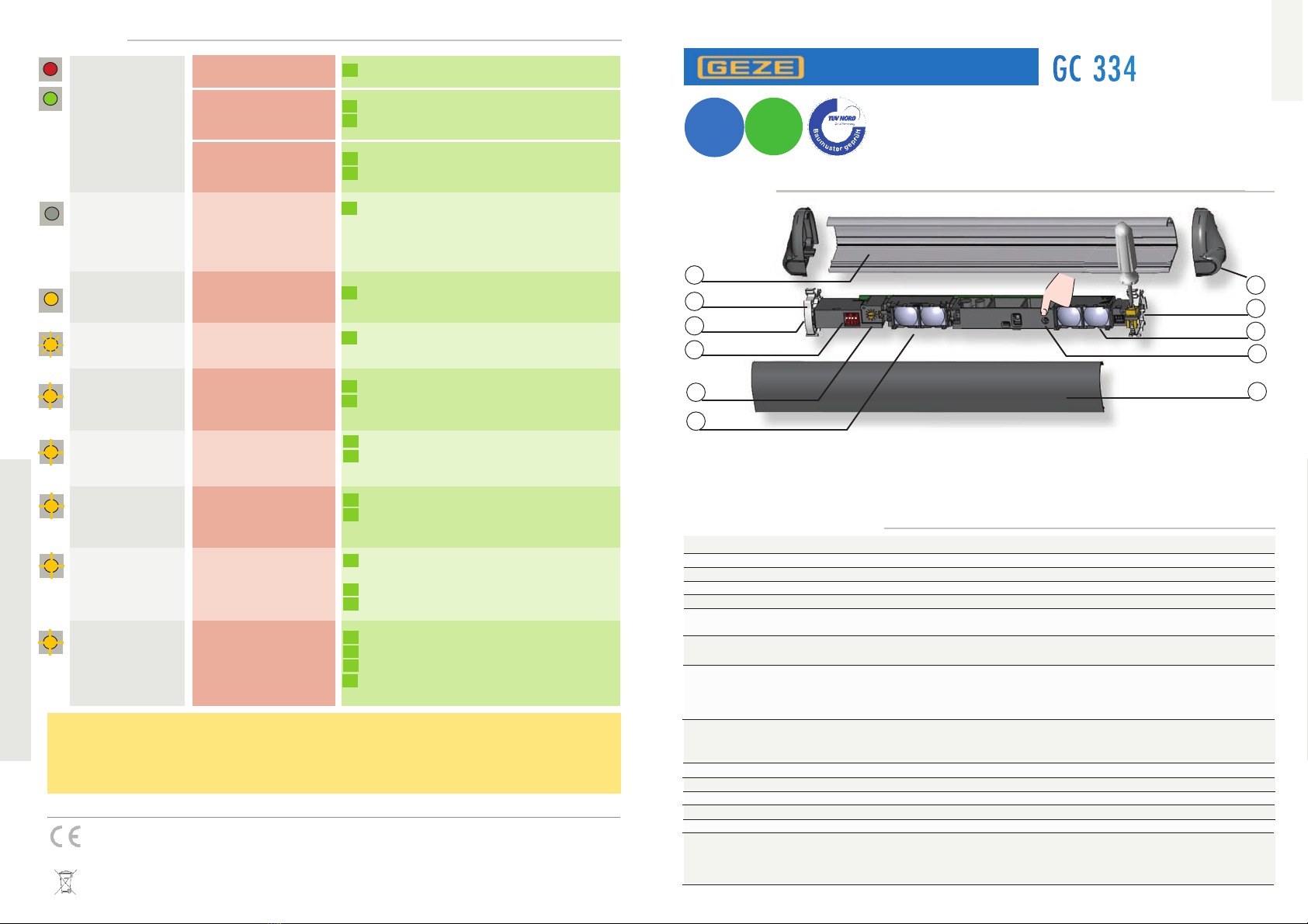
SIGNAUX LED
La LED orange
clignote 1x toutes
les 3 secondes.
La LED orange reste
allumée en
permanence.
La LED orange
clignote vite.
La LED rouge ou
verte s’allume
sporadiquement ou
reste allumée.
Lancez une calibration.
Renvoyez le détecteur à l’usine pour vérification
technique.
Maintenez le bouton poussoir enfoncé pour
confirmer le réglage du DIP-switch.
Coupez et restaurez l’alimentation.
Si la LED orange clignote encore, changez le détecteur.
Le détecteur ne
réagit pas mais un
calibrage peut être
lancé.
Vérifiez le câblage.
- Connectez le ROUGE et le BLEU à la sortie
de test de l’opérateur.
- Si l’opérateur n’est pas monitoré : branchez le
BLEU sur 0 V et le ROUGE sur +12 V - 30 V DC.
La LED orange
clignote 2x toutes
les 3 secondes.
La LED orange
clignote 3x toutes
les 3 secondes.
La LED orange
clignote 4x toutes
les 3 secondes.
La LED orange
clignote 5x toutes
les 3 secondes.
Vérifiez l’alimentation.
Réduisez la longueur du câble ou changez le câble.
Vérifiez le câblage entre modules.
Lancez un comptage des modules :
maintenez enfoncé le bouton poussoir du MASTER.
L’alimentation est trop basse
ou trop haute.
Le détecteur signale un
problème interne.
Mauvais réglage de la zone
de non couverture.
La surveillance est activée,
mais l’entrée de surveillance
n’est pas alimentée.
Erreur de communication
entre modules.
Le détecteur rencontre
un problème de mémoire.
Réglage DIP-switch en
attente de confirmation.
Le détecteur reçoit
trop peu d’énergie IR.
Mauvaise calibration
Le détecteur est perturbé
par des lampes ou un autre
détecteur proche.
Sélectionnez une autre fréquence par module (DIP 2).
Lancez une calibration.
Erreur de calibration Vérifiez la hauteur de montage.
Changez la position de la vis de calibration.
Lancez une calibration.
Désactivez l’arrière-plan (DIP 3: OFF).
Vérifiez si le DIP 4 est reglé correctement.
Lancez une calibration.
Lancez une calibration et sortez du champ
de détection.
Changez l’angle des spots.
Désactivez l’arrière-plan (DIP 3: OFF).
1
2
3
4
5
6
7
8
9
10
11
DRAFT
E
R
L
A
U
B
T
Z
E
R
T
I
F
I
Z
I
E
R
U
N
G
N
A
C
H
EN 16005
E
N
A
B
L
E
S
A
C
C
O
R
D
A
N
C
E
W
I
T
H
E
R
L
A
U
B
T
Z
E
R
T
I
F
I
Z
I
E
R
U
N
G
N
A
C
H
DIN 18650
E
N
A
B
L
E
S
A
C
C
O
R
D
A
N
C
E
W
I
T
H
SPECIFICATIONS TECHNIQUES
DESCRIPTION
FRANCAIS
Détecteur de sécurisation
pour portes battantes automatiques
infrarouge actif avec suppression de l’arrière-plan
400 mm (L) x 70 mm (P) (4 spots à 2 m de hauteur de montage)
1,3 m à 3,5 m
64 ms (typ)
infini
12 V - 24 V AC +/-10% ; 12 V - 30 V DC -5%/+10%
(l’appareil doit uniquement fonctionner sur basse tension de protection (SELV) avec coupure électrique sûre)
95 mA @ 24 V AC/ 70 mA @ 24 V DC; 170 mA @ 12 V AC/ 130 mA @ 12 V DC (MASTER)
85 mA @ 24 V AC/ 60 mA @ 24 V DC; 180 mA @ 12 V AC/ 113 mA @ 12 V DC (autres modules)
2 relais (libres de potentiel)
42 V AC/DC
1 A (resistif)
30 W (DC) / 42 VA (AC)
1 optocoupleur (libre de potentiel)
30 V
Etat haut: > 10 V; Etat bas: < 1 V
4 (jusque 6 si 24 V DC)
min 5% à une longueur d’ondes IR de 850 nm
IP53
-25 °C à +55 °C; 0-95% humidité relative, non condensante
20 ans
DIN 18650-1 ch. 5.7.4; BS 7036-2*; EN 16005 ch. 4.6.8;
EN 12978; EN 61508; IEC 61496-2; BGR 232;
EN ISO 13849-1 Performance Level «c» CAT. 2
(à condition que l’opérateur surveille le détecteur au moins une fois par cycle de porte)
Technologie :
Champ de détection :
Hauteur de montage :
Temps de réponse :
Temps de présence max:
Alimentation :
Consommation de courant max. :
Sorties :
Tension max. aux contacts :
Courant max. aux contacts :
Pouvoir de coupure max. :
Entrée:
Tension max. aux contacts:
Seuil de tension:
Nombre max. de modules:
Reflectivité:
Degré de protection:
Gamme de température :
Durée de vie estimée :
Conformité aux normes :
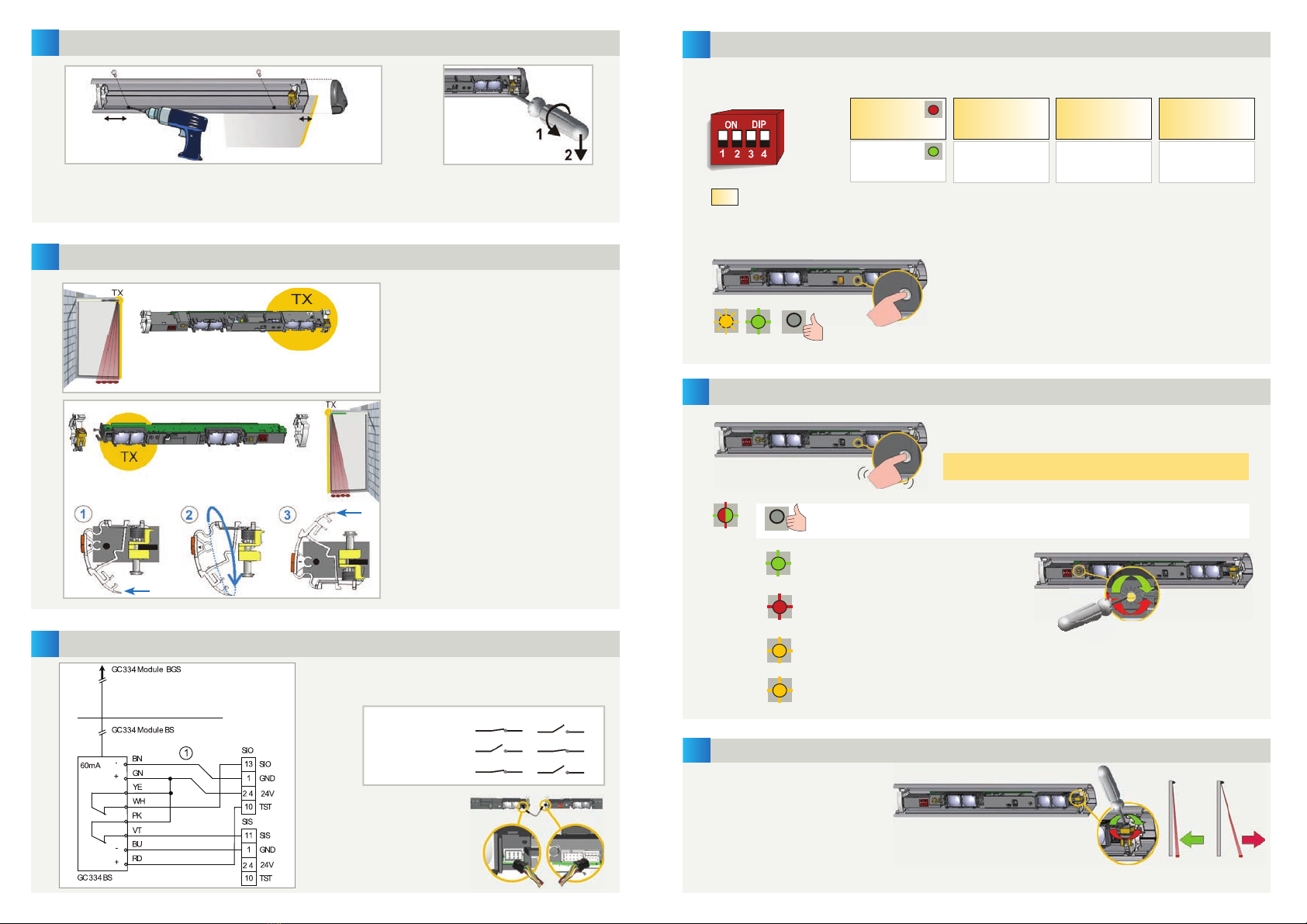
1. profilé
2. clip de support
3. connecteur principal
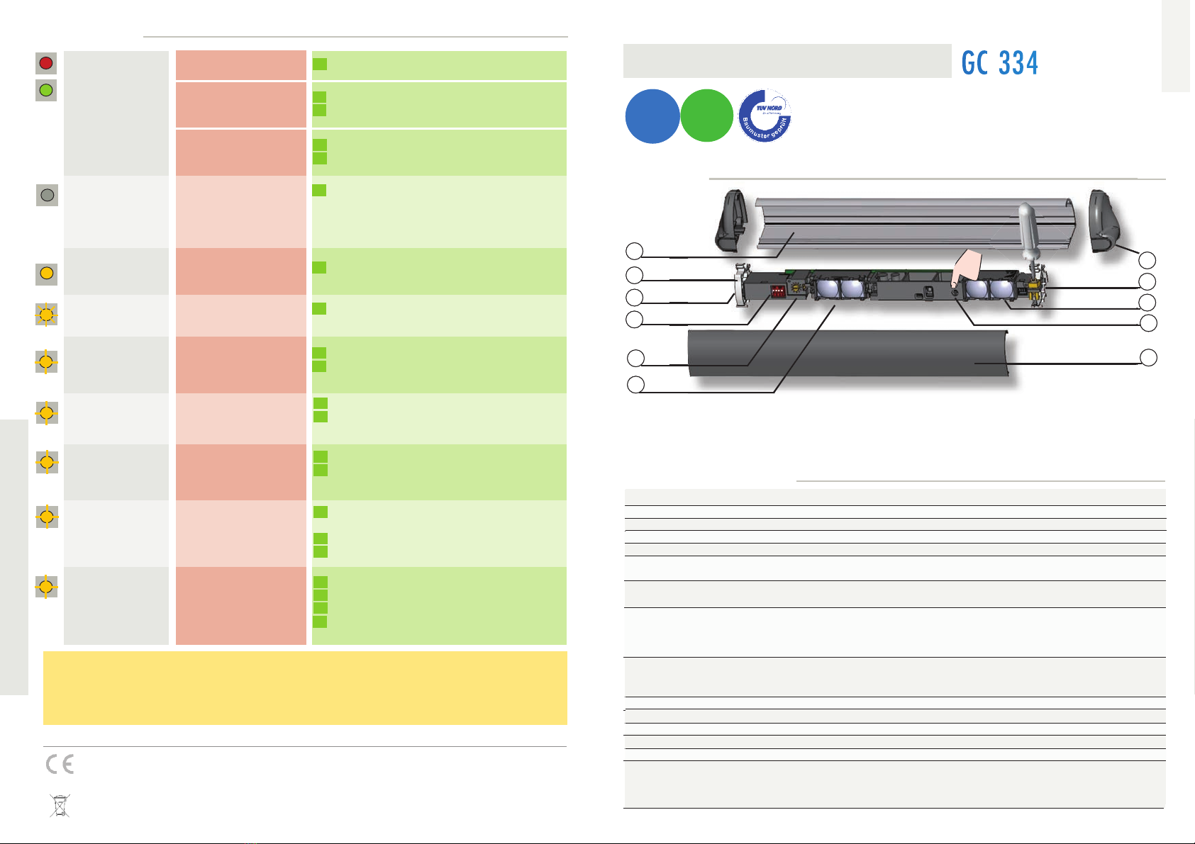
4. DIP-switch
5. vis de calibrage
6. recepteur
7. flasque
8. clip avec vis d’ajustement angulaire
9. émetteur (TX)
10. bouton poussoir
11. face avant
L
es spécifications techniques sont susceptibles de changer sans préavis
.
Toutes les valeurs sont mesurées dans des conditions optimales.
A CONSERVER POUR RÉFÉRENCE ULTÉRIEURE
PRÉVU POUR IMPRESSION EN COULEUR
Manuel d’utilisation pour produits à partir de la version 0500
Voir étiquette produit pour le numéro de série
* hauteur de montage max. pour une conformité à la BS 7036 (Royaume-Uni): 3,25 m
Other manuals for GC 334
1
Table of contents
Languages:
Other GEZE Accessories manuals