Braun A5S1-n Series User manual

A5S1…-n
A5S1-n-Manual_EN_Rev02 2021_JAN_19 Page 1 of 36
Manual
Ex nA Sensors Series A5S1…-n (non-sparking)
(Original operating manual)
valid for versions
A5S1DD0…-n (1x speed, signal range 0 Hz…25 kHz)
A5S1DD3…-n (1x speed / 1x direction, signal range 0 Hz…25 kHz)
A5S1DD4…-n (2x speed, phase shifted, signal range 0 Hz…25 kHz)
A5S1DS0…-n (1x speed, signal range 0 Hz…12 kHz)
A5S1DS3…-n (1x speed / 1x direction, signal range 0 Hz…12 kHz)
A5S1DS4…-n (2x speed, phase shifted, signal range 0 Hz…12 kHz)
(valid from Serial-No. 1602050001)
A5S view
(version A5S1DS0M2210B48-n shown)
Speed Sensors
for Hazardous Areas zone 2
based on Differential-Hall-Effect Principle
TÜV certified for IEC 61508:2010; SIL 3
DIN EN ISO 13849-1:2016; PL e; Kat. 3
DIN EN ISO 13849-2:2012; PL e; Kat. 3
IEC 62061:2015; SILCL 3

A5S1-n-Manual_EN_Rev02 2021_JAN_19 Page 2 of 36
Table of Contents
Contents Page
Table of Contents........................................................................................................................................................2
1General Information ...........................................................................................................................................3
1.1 List of Figures..............................................................................................................................................3
1.2 List of Abbreviations ....................................................................................................................................4
1.3 Application characteristics...........................................................................................................................5
1.4 Mounting of the Sensor ...............................................................................................................................5
1.4.1 Notes on Pole Wheel..........................................................................................................................6
1.4.2 Positioning of Sensor..........................................................................................................................6
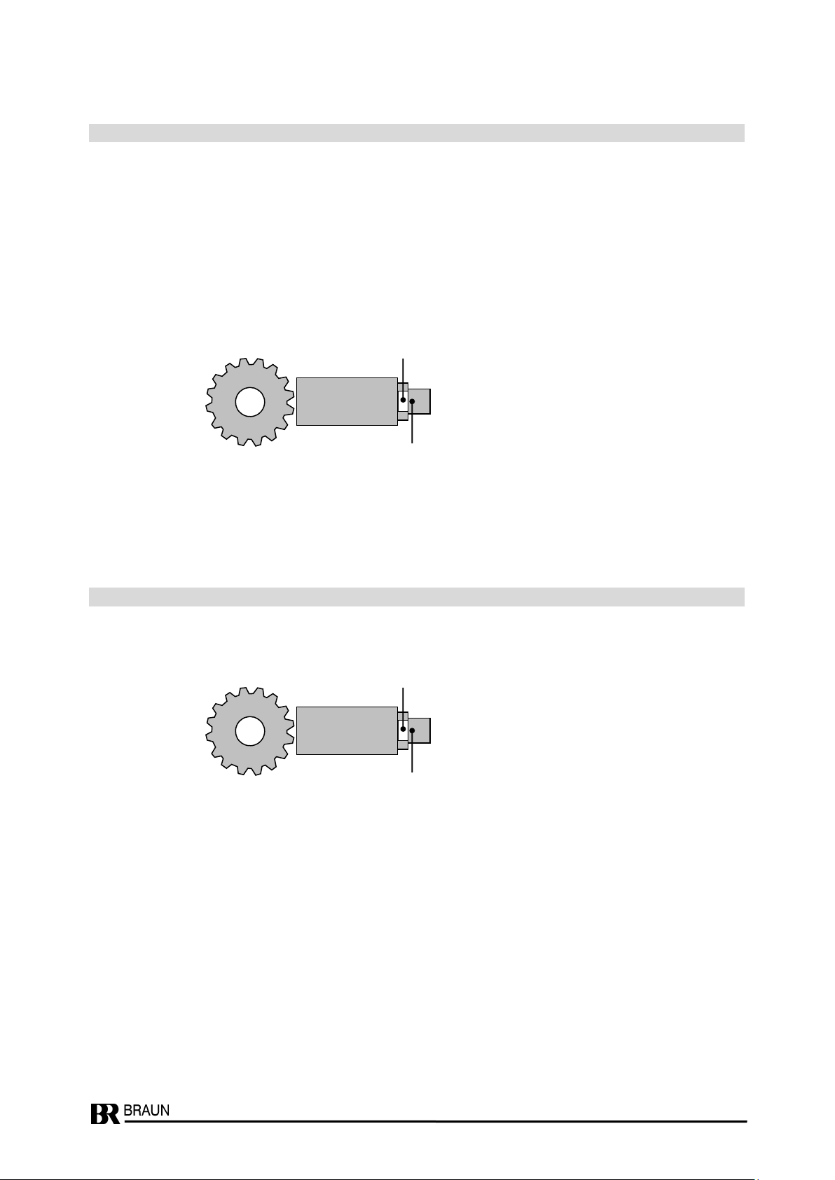
1.4.2.1 Alignment of Sensor.......................................................................................................................6
1.4.2.2 Recommended Air Gap..................................................................................................................7
1.4.3 Maximum fastening torques / wrench sizes / thickness of BRAUN nuts.............................................7
1.5 Connection (pin assignment resp. wire assignment) ...................................................................................8
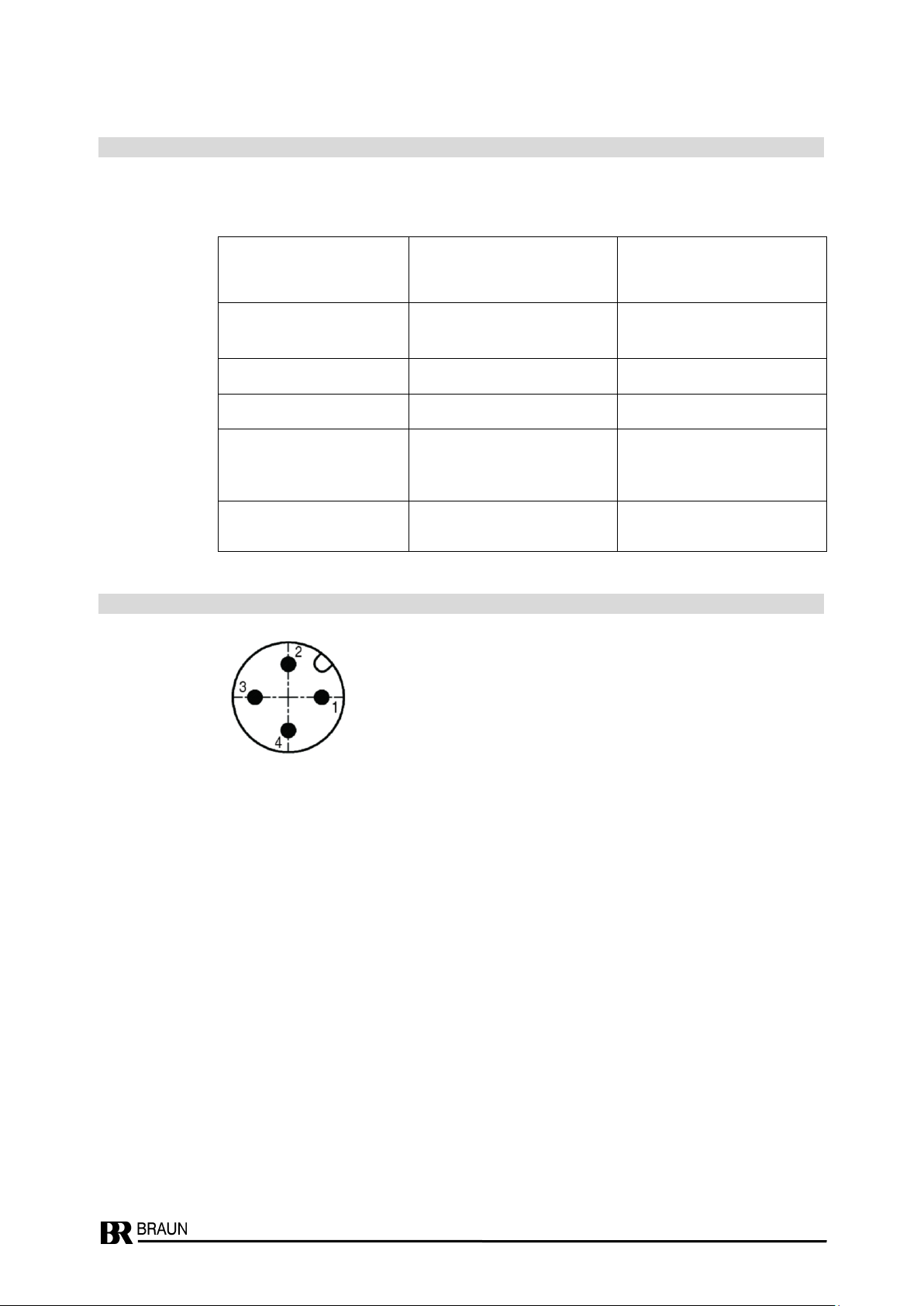
1.6 Arrangement of Pins in Sensor Plug ...........................................................................................................8
1.7 Signal Transmission ....................................................................................................................................9
1.8 Direction of rotation signal for sensor series A5S1DD3…-n / A5S1DS3…-n.............................................10
1.9 Speed signal f2 (phase shifted) for sensor series A5S1DD4…-n / A5S1DS4…-n.....................................10
1.10 Level and shape of the output signal.........................................................................................................11
1.11 Ordering Key for Sensors of A5S1…-n Series...........................................................................................12
1.12 Safety Data................................................................................................................................................13
1.13 General Certificates / Approvals ................................................................................................................13
1.13.1 Certification IEC 61508:2010; SIL 3..................................................................................................13
1.13.2 Certification DIN EN ISO 13849-1:2016; PLe; Kat. 3........................................................................13
1.13.3 Certification DIN EN ISO 13849-2:2012; PLe; Kat. 3........................................................................13
1.13.4 Certification IEC 62061:2015; SILCL 3 ..............................................................................................13
1.13.5 SIL 3 Certificate ................................................................................................................................14
1.13.6 EU Declaration of Conformity ...........................................................................................................15
2Hazardous protection ......................................................................................................................................16
2.1 Relevant technical Data for Hazardous Area.............................................................................................16
2.2 ATEX Certification of the Input Circuit .......................................................................................................16
2.3 Explosive relevant Certificates / Approvals................................................................................................16
2.3.1 ATEX ................................................................................................................................................16
2.3.2 IECEx ...............................................................................................................................................16
2.3.3 USA (NEC) and Canada (CEC) ........................................................................................................16
2.3.4 EAC Ex.............................................................................................................................................16
2.3.5 ATEX Type Examination Certificate ..................................................................................................17
2.3.6 IECEx Certificate of Conformity ........................................................................................................20
2.3.7 NEC/CEC Certificate of Conformity ..................................................................................................26
2.3.8 EAC Ex TR CU Certificate ................................................................................................................28
3Safety Notes for Installation and Operation...................................................................................................32
3.1 General Instructions ..................................................................................................................................32
3.2 EMI............................................................................................................................................................32
3.3 Safety note about metallic abrasion in the machine ..................................................................................32
3.4 Safety Notes on Installation.......................................................................................................................32
3.4.1 Initial Commissioning and Installation...............................................................................................32
3.5 Safety Notes on Operation ........................................................................................................................32
3.5.1 Machine Maintenance or Overhaul...................................................................................................32
4Technical Specifications..................................................................................................................................33
4.1 Conformity to Standards............................................................................................................................33

A5S1-n-Manual_EN_Rev02 2021_JAN_19 Page 3 of 36
4.2 Power Supply ............................................................................................................................................33
4.3 Signal Output.............................................................................................................................................33
4.4 Speed (Frequency-) Range.......................................................................................................................33
4.5 Signal Transmission ..................................................................................................................................33
4.6 Electrical Protective Measures ..................................................................................................................33
4.7 Connection ................................................................................................................................................33
4.8 Permissible Ambient Temperature.............................................................................................................33
4.9 Installation Dimensions .............................................................................................................................33
4.10 Cable diameters of BRAUN Cables...........................................................................................................34
4.11 Weight .......................................................................................................................................................34
5Accessories (optional).....................................................................................................................................34
6Useful Lifetime, Proof Test Interval and replacement of A5S sensors ........................................................34
7Dimensions at different Connection Types....................................................................................................35
8Revision Notes .................................................................................................................................................36
1 General Information
1.1 List of Figures
Figure 1: Adjustment to the profile edges ......................................................................................................... 5
Figure 2: Alignment of sensor........................................................................................................................... 6
Figure 3: Information on profile size..................................................................................................................7
Figure 4: SIL 3 Certificate ............................................................................................................................... 14
Figure 5: EU Declaration of Conformity .......................................................................................................... 15
Figure 6: ATEX Type Examination Certificate part 1....................................................................................... 17
Figure 7: ATEX Type Examination Certificate part 2....................................................................................... 18
Figure 8: ATEX Type Examination Certificate part 3....................................................................................... 19
Figure 9: IECEx Certificate of Conformity part 1............................................................................................. 20
Figure 10: IECEx Certificate of Conformity part 2............................................................................................. 21
Figure 11: IECEx Certificate of Conformity part 3 ............................................................................................. 22
Figure 12: IECEx Certificate of Conformity part 4............................................................................................. 23
Figure 13: IECEx Certificate of Conformity part 5............................................................................................. 24
Figure 14: IECEx Certificate of Conformity part 6............................................................................................. 25
Figure 15: NEC/CEC Certificate of Conformity part 1 ....................................................................................... 26
Figure 16: NEC/CEC Certificate of Conformity part 2 ....................................................................................... 27
Figure 17: EAC Ex TR CU Certificate part 1..................................................................................................... 28
Figure 18: EAC Ex TR CU Certificate part 2..................................................................................................... 29
Figure 19: EAC Ex TR CU Certificate part 3..................................................................................................... 30
Figure 20: EAC Ex TR CU Certificate part 4..................................................................................................... 31
Figure 21: Dimensions at different connection types ........................................................................................ 35

A5S1-n-Manual_EN_Rev02 2021_JAN_19 Page 4 of 36
1.2 List of Abbreviations
Abbreviation
Meaning
altern.
alternative
API
Technical standards of the "American Petroleum Institute"
A5S
BRAUN GmbH Sensor series
ATEX
stands for ATmosphère Explosibles (meaning the ATEX EU directives for explosion protection)
DIN
German Institute for Standardisation (Deutsches Institut für Normung)
EMC
Electromagnetic compatibility
EN
European Norm
Ex nA
Type of protection "non-sparking", approval for hazardous areas zone 2
F/R
Forward/Reverse (Forward/Backward)
IEC
International Electrotechnical Commission
incl.
inclusive
IPxx
Ingress Protection Number xx according to DIN EN 60529
ISO
International Organization for Standardization
max.
maximum
min.
minimum
MTTFd
Mean Time To Failure dangerous
n
Short term for Speed
NEMAx
National Electrical Manufacturers Association Number x
Nm
Newton meter
PELV
Protective Extra Low Voltage
PFDavg
Probability of Failure on Demand average
RPM
Revolutions Per Minute
sec
second
SELV
Safety Extra Low Voltage
SILx
Safety Integrity Level x
TMR
Triple Modular Redundant
Ub
+ supply voltage
UL
Underwriter Laboratories
Vdc or
V dc
Volt direct current

A5S1-n-Manual_EN_Rev02 2021_JAN_19 Page 5 of 36
Figure 1: Adjustment to the profile edges
1.3 Application characteristics
Speed sensors for applications such as turbines, compressors, expanders, etc. in hazardous
areas of zones 2. The sensors are approved as “non-sparking/non-incendive”equipment with
protection class Ex nA IIC, temperature class T4 (at Ta = -40 ° C to +125 ° C) or temperature
class T6 (at Ta = -20 ° C to + 40 ° C). The power supply must comply with the regulations for this
(see chapter 4.2 "Power supply" or Chapter 3 "Safety instructions"). Safety classification up to
SIL 3 / IEC 61508:2010 resp. DIN EN ISO 13849-1:2016 PL e Kat. 3, DIN EN ISO 13849-2:2012
PL e Kat. 3 and IEC 62061:2015; useable in applications up to SILCL 3 as speed sensors.
Their low end of 0 Hz allows monitoring the machine down to zero speed. They are contact-free,
wear-free, maintenance-free and unsusceptible versus external magnetic stray fields and
machine vibration.
Sensors A5S1DD0…-n and A5S1DS0…-n for detection of rotational speed
Single Channel, the output provides the rotational speed as a single-track frequency signal.
Sensors A5S1DD3…-n and A5S1DS3…-n for detection of rotational speed and direction of
rotation
Dual Channel, 1 track = rotational speed as frequency, 1 track = F/R status as binary signal.
Sensors A5S1DD4…-n and A5S1DS4…-n for detection of rotational speed and direction of
rotation with two phase-shifted speed signals
Dual Channel, the output provides the rotational speed as a twin-track frequency signal (phase
shifted). Suitable for external direction detection with enhanced safety.
1.4 Mounting of the Sensor
The sensor should be mounted in radial direction so that it points to the axis of rotation of the
rotating profile. An arrangement parallel to the axis of rotation for frontal scanning is also
possible. Then, a possible axial displacement in the machine must be considered. All our
information applies to radial scanning.
For mounting, it is best to have the same thread in the fixed part. The sensor is then fixed in the
correct position with the supplied nut.
The mounting may be made flush in any material; several sensors can also be placed close to
each other.
Slots for positioning with
NPT at rear end
Mounting preferably in radial
direction and in alignment
with the profile
rotation of
target
wrench planes at rear or front end
of sensor
profile
edge
Adjustment to the profile edges

A5S1-n-Manual_EN_Rev02 2021_JAN_19 Page 6 of 36
Figure 2: Alignment of sensor
1.4.1 Notes on Pole Wheel
The pole wheel must be made of ferromagnetic steel. Non-ferrous material, stainless steel or
plastics do not work.
The grooves / bolts of the pole wheel must be equidistant; otherwise the speed signal will be
unsteady.
The pole wheel should have no damage or burrs; otherwise the speed signal can become
unsteady. If there is any damage, increasing the gap in the air can eliminate a possible fault
(double pulses).
1.4.2 Positioning of Sensor
1.4.2.1 Alignment of Sensor
The sensor must be aligned with the flanks of the profile to be scanned. It is correctly installed if
the two planes at the end of the sensor (which also serve as wrench planes for screwing in)
point in the direction of the profile or perpendicular to the profile edges (for example the tooth
flanks of a gear).
A deviation of up to ± 20 ° is permitted.
Correct alignment of the sensor
Incorrect alignment of the sensor

A5S1-n-Manual_EN_Rev02 2021_JAN_19 Page 7 of 36
Figure 3: Information on profile size
D
W
T
Profile size of a
grooved wheel
D = min. 3 mm
W = min. 3 mm
T = min. 5 mm
1.4.2.2 Recommended Air Gap
The recommended air gap between the sensor front surface and the rotating part must be
observed. It increases with the size of the profile: For cams or milled grooves with their width,
distance and depth, for a gear with its module (= diameter / number of teeth). The field between
grooves or cams must be at least as large as the specified width (W), the depth D = at least 3
mm. Thickness of a gear or length (T) of a milled recess of at least 5 mm (plus a possible axial
displacement).
The guideline values given below for the profile size (D / W / T) of a rotor are the minimum
dimensions, they may be exceeded in any direction. However, the maximum permissible air gap
between the sensor and the pole wheel will not increase.
Air gap in dependency of profile size
A5S1DS0…-n
A5S1DD0…-n
A5S1DS3…-n and DS4…-n
A5S1DD3…-n and DD4…-n
Module of a
gear wheel
Diametrical Pitch
approx.
min. width W of a
groove wheel
Recommended
air gap
Recommended
air gap
m1
25.40 mm
3 mm
0.5 –0.8 mm
--
m1.5
16.93 mm
3 mm
0.5 –1.0 mm
--
m2
12.70 mm
3 mm
0.8 –1.5 mm
0.3 –0.8 mm
m3
8.47 mm
3 mm
0.8 –2.0 mm
0.3 –1.2 mm
m4
6.35 mm
3 mm
1.0 –2.5 mm
0.5 –1.5 mm
1.4.3 Maximum fastening torques / wrench sizes / thickness of BRAUN nuts
Nut
Maximum
fastening torque
wrench size
thickness
(+/- 0.5 mm)
M12 x 1
12 Nm
WS 19
6 mm
M14 x 1
25 Nm
WS 22
4 mm
M14 x 1.5
25 Nm
WS 22
7 mm
3/4“-16
25 Nm
WS 28
10 mm
M16 x 1
35 Nm
WS 24
8 mm
M18 x 1
50 Nm
WS 26
9 mm
3/4“-20
50 Nm
WS 24
6 mm
M18 x 1.5
50 Nm
WS 26
9 mm
5/8“-18
50 Nm
WS 24
10 mm
M22 x 1
75 Nm
WS 30
6 mm

A5S1-n-Manual_EN_Rev02 2021_JAN_19 Page 8 of 36
1.5 Connection (pin assignment resp. wire assignment)
All sensors described here can have different dimensions and different connection types.
For the connections applies to the different types:
Assignment
with plug
pin no.
with open cable ends of
BRAUN cables
wire color
Signal output 1:
(speed signal f1)
4
white
Common zero
3
green
+ sensor supply Ub
1
brown
Signal output 2:
(speed signal f2 resp.
rotation direction signal)
2
red (at Teflon® cable)
resp.
yellow (at PVC cable)
Screen (not connected to
sensor housing)
black
1.6 Arrangement of Pins in Sensor Plug

A5S1-n-Manual_EN_Rev02 2021_JAN_19 Page 9 of 36
1.7 Signal Transmission
The possible transmission distance is essentially determined by the highest occurring signal
frequency, the properties of the transmission line and the input of the connected receiving
device.
When connected to our equipment for fixed installation, signal frequency of 25000 Hz can be
safely transmitted over a distance of up to 500 m. If the signal frequency is lower, a corres-
pondingly longer transmission distance applies. The cable is based on a 3-core or 4-core
shielded version LiYCY or LiTCT with 3x0.5 mm2or 4x0.5 mm2, as supplied by us (R <36 Ohm /
km, C <150 pF / m).
The signal frequency in Hz is calculated with a uniformly divided profile by:
Number of poles x speed / 60.
For narrow poles, the effective frequency must be set higher in accordance with the relationship
between pole and gap.
Important in the transmission:
A continuous good shielding must be provided. The shield must be connected directly to a shield
rail on the receiving side. Never transmit multiple signals under one common screen!
Lay transmission line separately from sources of interference.

A5S1-n-Manual_EN_Rev02 2021_JAN_19 Page 10 of 36
1.8 Direction of rotation signal for sensor series A5S1DD3…-n / A5S1DS3…-n
The sensor indicates the direction of rotation by a constant signal, which is either high or low
depending on the direction (see below for level values). The change is instantaneous as soon as
a pole pitch (e.g., 1 tooth) has passed the sensor. At standstill, the last reported direction is
retained. A hysteresis in the direction change or the combination with a speed lower limit must
be implemented in the connected evaluation unit.
The assignment between the signal level and the direction of rotation results from the installation
position of the sensor. For the purpose of predetermination, a mark o is placed on the type strip
of the sensor. If the profile wheel rotates clockwise in the viewing direction to this mark, the
output has high level, otherwise low level.
Relationship between mark and direction signal
o mark visible and rotation in clockwise direction = direction output high
o mark visible and rotation in counterclockwise direction = direction output low
o mark not visible: output inverse to above
1.9 Speed signal f2 (phase shifted) for sensor series A5S1DD4…-n / A5S1DS4…-n
The sensor provides two phase shifted frequency signals f1 and f2:
Relationship between mark and phase position
o mark visible and rotation in clockwise direction: f1 is ahead
o mark visible and rotation in counterclockwise direction: f2 is ahead
o mark not visible: phase position inverse to above
wrench plane
o mark
wrench plane
o mark

A5S1-n-Manual_EN_Rev02 2021_JAN_19 Page 11 of 36
1.10 Level and shape of the output signal
Rectangular pulses at low frequencies and with short lines. At higher frequencies and with long
lines, the signal at the receiver becomes a saw tooth tread profile.
Pulse pitch depends on the profile shape, when sampling a gear wheel profile, it is about 1:1.
The level is the same over the entire speed range. The built-in output stage can pull loads to
zero and to operating voltage equally strong.
The signal level during no-load running is almost equal to the supply voltage. The diagrams
show how it gets smaller when the current load increases (the high-level decreases, the low
level becomes higher). If the permissible maximum load of 25 mA is exceeded, the level drops
sharply. The sensor is not damaged, the output is short-circuit proof.
The maximum load corresponds to a load resistance of 1000 ohms at 24 V supply voltage, 500
ohms are permissible with 12 V supply voltage.
Output level with load against zero
Output level with load against Ub (+ supply)
high level
low level
volts
Ub-1.5V
Ub-2.5V
1V
maximum
load
high level
low level
volts
Ub
Ub-1.5V
maximum
load
high level
1V
low level
2V
output
+ sensor supply Ub
common zero
output
+ sensor supply Ub
common zero

A5S1-n-Manual_EN_Rev02 2021_JAN_19 Page 12 of 36
1.11 Ordering Key for Sensors of A5S1…-n Series
A5S1 b c d e f g - I -n
Signal frequency Cable length in meters
b = DD : 0 Hz…25 kHz i = 1m to 99m*
b = DS : 0 Hz…12 kHz *only with versions with fixed cable
Signal output Nominal thread length in mm
c = 0 : 1x frequency Standard length for thread:
c = 3 : 1x frequency / 1x direction*g = 50, 80, 120 : M12x1 (1210)
c = 4 : 2x frequency, phase shifted*g = 50, 90, 154 : M14x1 (1410)
*minimum nominal thread length 74 mm g = 50, 90, 154 : M14x1.5 (1415)
g = 48 : M16x1 (1610)
Unit of shaft diameter g = 80, 154 : M16x1.5 (1615)
d = M : metric g = 48, 94 : M18x1 (1810)
d = N : inch and ½-NPT at end of sensor g = 50, 74, 94 : M18x1.5 (1815)
d = U : inch g = 48, 94 : M22x1 (2210)
g = 90 : 3/4“-16 (3416)
Thread of shaft diameter g = 90 : 3/4“-20 (3420)
Standard thread: g = 48, 100, 165 : 5/8“-18 (5818)
e = 1210 : M12x1 (metric) other lengths on request
e = 1410 : M14x1 (metric)
e = 1415 : M14x1.5 (metric) Connection type
e = 1610 : M16x1 (metric) f = B : screw-plug-in connection
e = 1615 : M16x1.5 (metric) f = C : fixed PVC cable
e = 1810 : M18x1 (metric) f = T : fixed Teflon®cable
e = 1815 : M18x1.5 (metric)
e = 2210 : M22x1 (metric)
e = 3416 : 3/4“-16 (inch)
e = 3420 : 3/4“-20 (inch)
e = 5818 : 5/8“-18 (inch)
other threads or flat shafts on request
Examples:
A5S1DD0M1210B80-n = Signal frequency up to 25 kHz, signal output 1x frequency, thread M12x1,
screw-plug-in connection, nominal length 80 mm
A5S1DS0M1415B90-n = Signal frequency up to 12 kHz, signal output 1x frequency, thread M14x1.5,
screw-plug-in connection, nominal length 90 mm
A5S1DD3M1615T80-5m-n = Signal frequency up to 25 kHz, signal output 1x frequency / 1x direction,
thread M16x1.5, Teflon®cable with 5m length, nominal length 80 mm
A5S1DS3M2210C94-5m-n = Signal frequency up to 12 kHz, signal output 1x frequency / 1x direction,
thread M22x1, PVC cable with 5m length, nominal length 94 mm
A5S1DD4U5818B100-n = Signal frequency up to 25 kHz, signal output 2x frequency (phase shifted),
thread UNF5/8-18, screw-plug-in connection, nominal length 100 mm
A5S1DS4M1815T94-2m-n = Signal frequency up to 12 kHz, signal output 2x frequency (phase shifted),
thread M18x1.5, Teflon®cable with 2m length, nominal length 94 mm

A5S1-n-Manual_EN_Rev02 2021_JAN_19 Page 13 of 36
1.12 Safety Data
See A5S-SIL-Datasheet.
1.13 General Certificates / Approvals
1.13.1 Certification IEC 61508:2010; SIL 3
The A5S…series differential hall effect sensors are TÜV certified according to IEC 61508:2010;
suitable up to SIL3 as stand-alone speed sensors for the functions:
•speed monitoring in connection with BRAUN E16 machine protection systems
•output of a correct speed signal (frequency) with an accuracy of +/- 1Hz
1.13.2 Certification DIN EN ISO 13849-1:2016; PLe; Kat. 3
The A5S… series differential hall effect sensors are TÜV certified according to DIN EN ISO
13849-1:2016; suitable up to PLe; Kat. 3 as stand-alone speed sensors for the functions:
•speed monitoring in connection with BRAUN E16 machine protection systems
•output of a correct speed signal (frequency) with an accuracy of +/- 1Hz
1.13.3 Certification DIN EN ISO 13849-2:2012; PLe; Kat. 3
The A5S… series differential hall effect sensors are TÜV certified according to DIN EN ISO
13849-2:2012; suitable up to PLe; Kat. 3 as stand-alone speed sensors for the functions:
•speed monitoring in connection with BRAUN E16 machine protection systems
•output of a correct speed signal (frequency) with an accuracy of +/- 1Hz
1.13.4 Certification IEC 62061:2015; SILCL 3
The A5S… series differential hall effect sensors are TÜV certified according to IEC 62061:2015;
suitable in applications up to SILCL 3 as stand-alone speed sensors for the functions:
•speed monitoring in connection with BRAUN E16 machine protection systems
•output of a correct speed signal (frequency) with an accuracy of +/- 1Hz

A5S1-n-Manual_EN_Rev02 2021_JAN_19 Page 14 of 36
1.13.5 SIL 3 Certificate
Figure 4: SIL 3 Certificate

A5S1-n-Manual_EN_Rev02 2021_JAN_19 Page 15 of 36
1.13.6 EU Declaration of Conformity
EU-Konformitätserklärung
EU Declaration of Conformity
BRAUN GmbH Industrie-Elektronik, Esslinger Str. 26, 71334 Waiblingen, Germany
erklärt in alleiniger Verantwortung, declares in its sole responsibility,
dass das Produkt:
Hall-Effekt Drehzahl-Sensor
that the product:
Hall-Effect Speed Sensor
Typ(en), types:
A5S1…-n
den genannten Europäischen Richtlinien und harmonisierten Normen entspricht, is in conformity with the
listed European Directives and harmonized standards.
EU-Richtlinie(n) / EU-Directive(s)
Norm(en), Standard(s)
2014/34/EU ATEX-Produktrichtlinie
2014/34/EU ATEX Product Directive
EN IEC 60079-0:2018
EN IEC 60079-15:2019
Kennzeichnung, marking:
II 3 G Ex nA IIC T* Gc
(T* = T4 or T6)
Konformitätsbescheinigung Nr.:
Type Examination Certificate No:
Aussteller, notified Body:
Benannte Stelle Nr., notified Body No:
CML 14ATEX4076X
Certification Management Limited B.V. (CML)
Hoogoorddreef 15
Amsterdam, 1101 BA
The Netherlands
2776
EU-Richtlinie(n) / EU-Directive(s)
Norm(en), Standard(s)
2014/30/EU EMV-Richtlinie
2014/30/EU EMC Directive
2014/35/EU Niederspannungsrichtlinie
2014/35/EU Low Voltage Directive (LVD)
2011/65/EU RoHS-Richtlinie
2011/65/EU RoHS Directive
EN 61326-1:2013
EN IEC 61326-3-2:2018
EN 61010-1:2010 + A1:2019 + A1:2019/AC:2019
EN IEC 63000:2018
Diese Erklärung gilt für alle Sensoren der Baureihe A5S1…-n, die mit Typenschildern der oben genannten
Typen versehen sind. Zusatzbezeichnungen an Stelle von ... stehen für die spezifische Ausführung.
This declaration is valid for all sensors of series A5S1…-n, which are provided with type labels of the types
mentioned above. Suffixes instead of ... are dummy variables for the specific model.
Unbedingte Beachtung aller Punkte der mitgelieferten Betriebsanleitung ist hierbei Voraussetzung.
Strict observance of the operation manual is an indispensable precondition, hereto.
Unterzeichnet für und im Namen der BRAUN GmbH / Signed for and on behalf of BRAUN GmbH
Waiblingen, 19-JAN-2021
_____________________________ _____________________________
Ort und Datum Albrecht Braun
Place and date Geschäftsführer
Managing Director
Figure 5: EU Declaration of Conformity

A5S1-n-Manual_EN_Rev02 2021_JAN_19 Page 16 of 36
2 Hazardous protection
The safety requirements as determined by EN 1127-1, as well as the corresponding national
regulations, are to be complied with regarding primary explosion protection, i.e. measures which
prevent or restrict the formation of a hazardous explosive atmosphere.
In the case of secondary hazardous protection, i.e. measures that prevent the ignition of an
explosive atmosphere surrounding electrical equipment, the series of standards applicable to
EN 60079 and the relevant national regulations must be observed.
2.1 Relevant technical Data for Hazardous Area
See the following certificates from chapter 2.3.1
2.2 ATEX Certification of the Input Circuit
II 3 G Ex nA IIC T4/T6 Gc
Type Examination Certificate: CML 14ATEX4076X
2.3 Explosive relevant Certificates / Approvals
2.3.1 ATEX
The series A5S1…-n Differential Hall Effect Ex sensors are certified according to ATEX Type
Examination Certificate No. CML 14ATEX4076X and are compliant according to ATEX Product
Directive 2014/34/EU.
Marking see ATEX Type Examination Certificate chapter 2.3.5.
2.3.2 IECEx
The series A5S1…-n Differential Hall Effect Ex sensors are certified according to IECEx
Certificate of Conformity No. CML 14.0030X.
Marking see IECEx Certificate of Conformity chapter 2.3.6.
2.3.3 USA (NEC) and Canada (CEC)
The series A5S1...-n Differential Hall Effect Ex sensors are certified for the USA and Canada
according to QPS Certificate of Conformity No. LR 1323-1.
Marking see NEC/CEC Certificate of Conformity chapter 2.3.7.
2.3.4 EAC Ex
The series A5S1…-n Differential Hall Effect Ex sensors are certified for EAC (Russia, Kazakh-
stan and Belarus Customs Union) according to TR-Certificate No. RU С-DE.ОБ01.B.00175 and
TR CU 012/2011.
Marking see EAC Ex TR CU Certificate chapter 2.3.8.

A5S1-n-Manual_EN_Rev02 2021_JAN_19 Page 17 of 36
2.3.5 ATEX Type Examination Certificate
Figure 6: ATEX Type Examination Certificate part 1

A5S1-n-Manual_EN_Rev02 2021_JAN_19 Page 18 of 36
Figure 7: ATEX Type Examination Certificate part 2

A5S1-n-Manual_EN_Rev02 2021_JAN_19 Page 19 of 36
Figure 8: ATEX Type Examination Certificate part 3

A5S1-n-Manual_EN_Rev02 2021_JAN_19 Page 20 of 36
2.3.6 IECEx Certificate of Conformity
Figure 9: IECEx Certificate of Conformity part 1
This manual suits for next models
14
Table of contents
Other Braun Accessories manuals
Popular Accessories manuals by other brands

Jumpking
Jumpking JKR1014G16 user guide

omi
omi RA Series Operation & maintenance manual

ECG
ECG ED 8026 instruction manual

Panasonic
Panasonic WRT 3367-8 installation manual

LINDR
LINDR Kontakt 40-K-us Green Line instruction manual

Hubbell
Hubbell Universal Cable Reel-Direct Drive UE24 Installation and maintenance instructions

Merlin Gerin
Merlin Gerin Masterpact NT installation manual

S&S Northern
S&S Northern Merlin CH4CO user guide

LEGRAND
LEGRAND Wiremold Modulink 880MP Series installation instructions

DirekTronik
DirekTronik LDS02 user manual

Dometic
Dometic 9500E installation instructions

ROSE DISPLAYS
ROSE DISPLAYS ANOFRAME ROUND NO LOAD WITH MULTICLIPS manual