FIP FLS M9.10 User manual

1
FLS M9.10
DUAL-PARAMETER ANALOG
MONITOR & TRANSMITTER
SAFETY INSTRUCTIONS
PACKING LIST
General Statements
• Do not install and service the product without following the Instruction
Manual
• This item is designed to be connected to other instruments which can be
hazardous if used improperly. Read and follow all associated instrument
manuals before using with it
• Product installation and wiring connections should only be performed by
qualied sta
• Do not modify product construction
Installation and Commissioning Statements
• Remove power to the instrument before wiring input and output connections
• Do not exceed maximum specications using the instrument
• To clean the unit, use only chemical compatible products
Please verify that the product is complete and without any damage.
The following items must be included:
• M9.10 Dual Analog Input Monitor and Transmitter
• Instruction Manual for M9.10 Dual Analog Input Monitor and Transmitter

2
DESCRIPTION
CONNECTIONS TO INSTRUMENTS
The new FLS M9.10 is a powerful monitor designed to manage analog and
frequency signals (or two analog signals) from every types of device which
provide a 4-20mA or a frequency output. M9.10 is equipped with a wide full
graphic display 4” which shows measured values clearly and a lot of other
useful information. Moreover, due to a multicolor display plus a powerful
backlight, measurement status can be determined easily from afar also.
A tutorial software guarantees a mistake-proof and fast set up of every
parameters. Calibration of 4-20mA input can be performed just xing 2
points as well as 1 point or using a reference value through a new “in-line
calibration”. Calibration of frequency input can be performed just xing
installation features or using a reference value through a new “in-line
calibration”. Two independent 4-20mA outputs are available to remote
measures to external devices. A proper combination of digital outputs (2 x SSR
and 2 x relays) allows customized setups for any process to be controlled.
TECHNICAL DATA
General
• Associated sensors: FLS hall eect ow sensors with frequency output, FLS
F6.60 ow magmeters family and every devices which generate a passive
or active 4-20mA signal.
• Materials:
- case: ABS
- display window: PC
- panel & wall gasket: silicone rubber
- keypad: 5-button silicone rubber
• Display:
- LC full graphic display
- backlight version: 3-colours
- backlight activation: User adjustable with 5 levels of timing
- update rate: 1 second
- enclosure: IP65 front
• Frequency input range (frequency): 0÷1000Hz
• Frequency accuracy (frequency): 0,5%
• Analog input range (frequency): 3,8÷21,0mA
• Analog input accuracy (frequency): 0,01mA
F3.00 F3.20 F6.30 F3.10 F3.05 F6.60 F6.61 F111
M9.10 X X - X - X X X
ULF F3.80 pH/
ORP200
pH/
ORP400
pH/
ORP600
pH/
ORP800
C150/
200
C100/
C300 C6.30
M9.10 X X X X X X - - -

3
Electrical
• Supply Voltage: 12 to 24 VDC ± 10% regulated
• Maximum current consumption: 300 mA
• FLS hall eect ow Sensor power:
- 5 VDC @< 20 mA
- Optically isolated from current loop
- Short circuit protected
• 2 x Current input power:
- 18VDC @ ≤ 20mA
• 2 x Current output:
- 4-20 mA, isolated, fully adjustable and reversible
- Max loop impedance: 800 Ω @ 24 VDC - 250 Ω @ 12 VDC
• 2 x Solid State Relay output:
- User selectable as MIN alarm, MAX alarm, ON-OFF mode, Timed mode,
Proportional mode, Frequency mode, Pulse Out (only for frequency input),
Window IN Alarm, Window OUT Alarm, O
- Optically isolated, 50 mA MAX sink, 24 VDC MAX pull-up voltage
- Max pulse/min: 300
- Hysteresis: User selectable
• 2 x Relay output:
- User selectable as MIN alarm, MAX alarm, ON-OFF mode, Timed mode,
Proportional mode, Frequency mode, Pulse Out (only for frequency input),
Window IN Alarm, Window OUT Alarm, O
- Mechanical SPDT contact
- Expected mechanical life (min. operations): 107
- Expected electrical life (min. operations): 105N.O./N.C. switching capacity
5A/240VAC
- Max pulse/min: 60
- Hysteresis: User selectable
Environmental
• Operating temperature: -20 to +70°C (-4 to 158°F)
• Storage temperature: -30 to +80°C (-22 to 176°F)
• Relative humidity: 0 to 95% not condensing
Standards & Approvals
• Manufactured under ISO 9001
• Manufactured under ISO 14001
• CE
• RoHS Compliant
• EAC
4
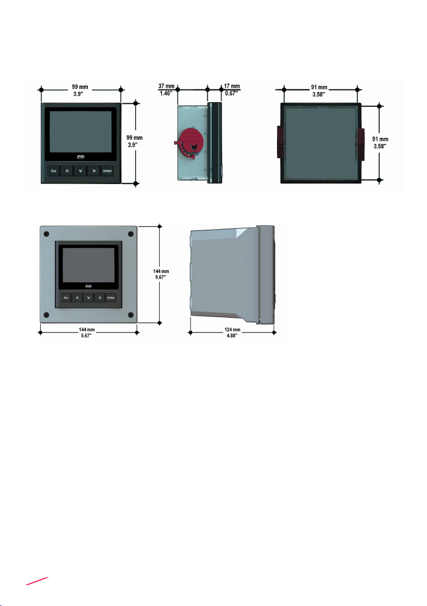
DIMENSIONS
INSTALLATION
Mechanical installation
Dual Analog Input Monitor and Transmitter M9.10 is available just in one
packaging for panel or wall installation.
The panel version is installed using the panel mounting kit (M9.SN1), while
the wall mounting version is got xing the panel mounting version on the wall
mounting kit (M9.KWX). The mounting kits can be ordered directly connected
to the monitor or separately and then simply installed on it.
PANEL MOUNTING
WALL MOUNTING

5
Panel installation
Fix instrument on the panel rotating by hand the xing snails (M9.SN1).
Wall installation
Use the panel mounting kit (M9.SN1) to x the M9.10 on the dedicated frontal
cutout of the wall mounting kit (M9.KWX).
Tighten front screws of box and waterproof connectors of cables, internally
mount caps on screw sites to get a IP65 watertight installation.
6
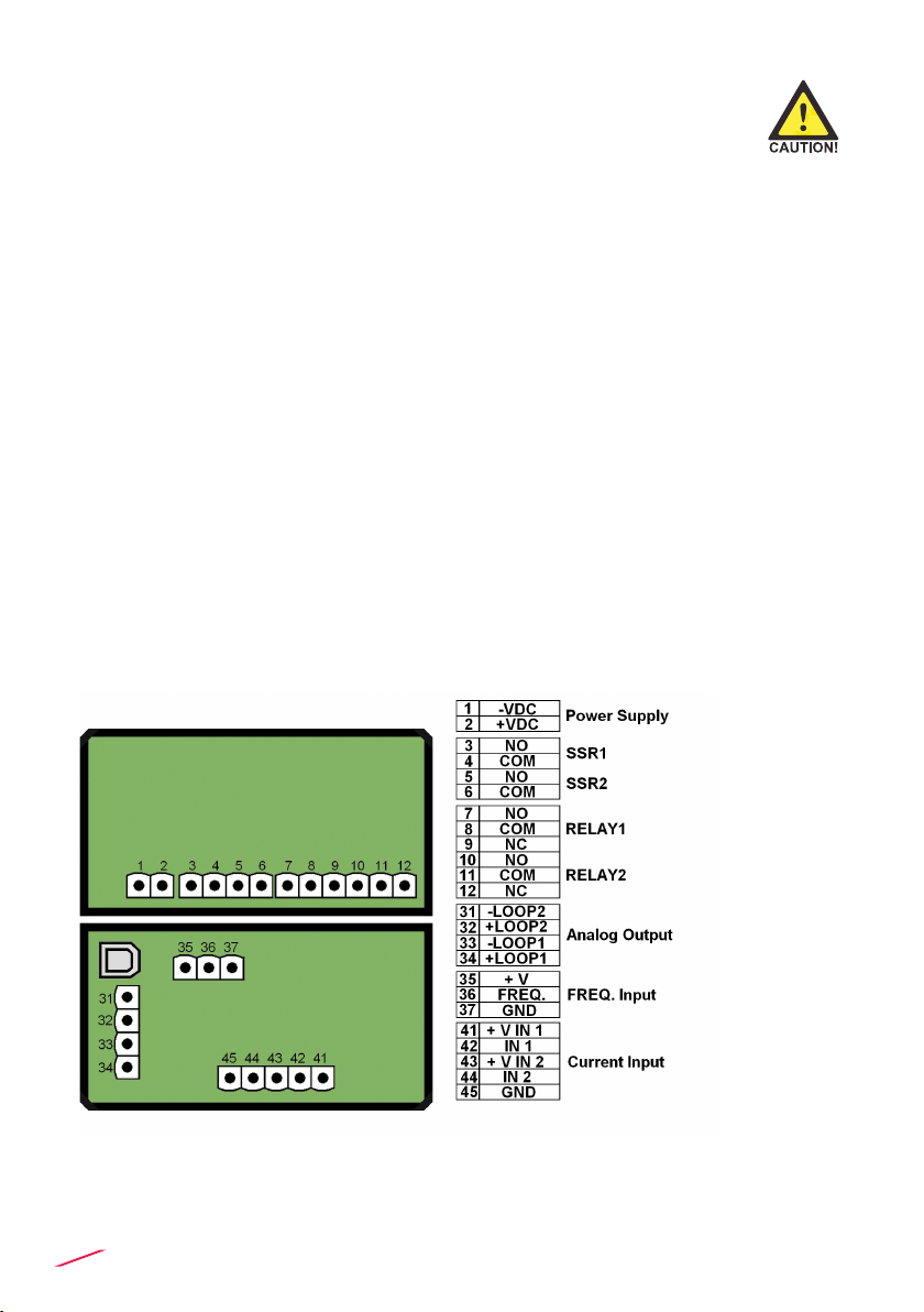
WIRING
REAR TERMINAL VIEW
General recommendation
Always ensure the power supply is switched o before working on the device.
Make wiring connections according to wiring diagrams.
• Terminals accept 26 to 12 AWG (0.08 to 2.5 mm2)
• Strip around 10 mm (0.4”) of insulation from the wire tips and tin bare ends to
avoid fraying.
• Ferrules are suggested when connecting more than one wire to a single
terminal.
• Remove the upper part of the terminals for an easy cabling.
• Insert wire tip or ferrule completely into the terminal and x with the screw
until nger tight.
• Do not route the sensor, DC power, or 4-20mA cables in conduit containing
AC power wiring. Electrical noise may interfere with sensor signal.
• Routing the sensor cable in grounded metal conduit can help prevent
electrical noise and mechanical damage.
Wall Installation
Use electrical cables with the proper external diameter for the liquid tight
connector:
PG11/PG9: external diameter between 2-7 mm (0.079-0.276”)
Refer to dedicated ow sensor manual for its wiring.
7
POWER WIRING DIAGRAM
Power Supply
12 - 24 VDC
12 - 24 VDC
+ VDC
- VDC
2
1
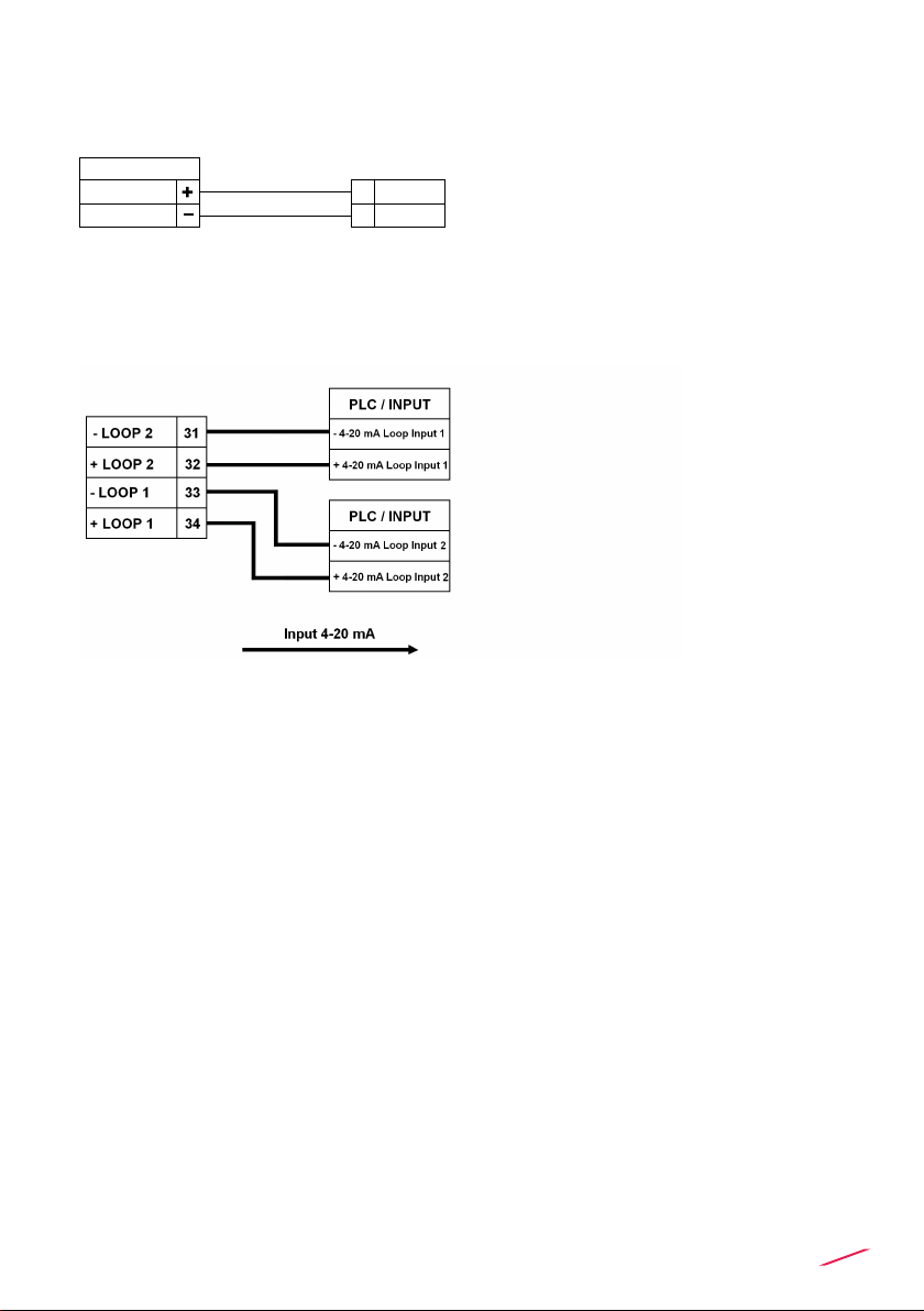
LOOP WIRING DIAGRAM

8
Internal PLC
connection
N.O.
COM
4
3
PLC
Imax = 50 mA
Power sup.
Power sup.
O.C. IN
O.C. IN
SOLID-STATE RELAY WIRING DIAGRAM
(FOR SSR1 AND SSR2)
INPUT WIRING DIAGRAM
Connection to a PLC with NPN input
Active loop devices Passive loop devices
Connection to a PLC with PNP input
N.O.
COM
4
3
PLC
Imax = 50 mA
Power sup.
Power sup.
O.C. IN
O.C. IN
Internal PLC
connection
Connection to a PLC / Instrument
digital input with separate Power
Supply
Connection to a PLC / Instrument
digital input for Voltage Free Contacts
(REED)
N.O.
COM
3
4
Power Supply
12 - 24 VDC
12 - 24 VDC
PLC / Instrument
Digital INPUT
Digital INPUT
Imax = 50mA
lmax = 50mA
lmax = 50mA
PLC
DIGITAL INPUT N
DIGITAL INPUT 2
DIGITAL INPUT 1
REF PLC
N.O.
Imax = 50 mA
Imax
COM
3
4
lmax = 50mA
lmax = 50mA
USB PORT
A USB port (type B) is available on the M9.10 PCB. The USB connection
allows the updating of device software. To update the software you need: USB
cable (M9.KUSB), the interface software "FLS Calibration System” and the
new updating software for M9.10 which are both downloadable from www.
snet.it freely on product page.

9
SOLID-STATE RELAY WIRING DIAGRAM
(FOR SSR1 AND SSR2)
RELAY WIRING DIAGRAM
(FOR RELAY 1 & RELAY 2)
The alarm is OFF during normal
operation and goes ON according to
Relay settings
The alarm is ON during normal
operation and goes OFF according to
Relay settings
The alarm is o during normal
operation and goes ON according to
Relay setting.
If Imax > 50 mA use external Relay
Connection to an User
NO
10
11
12
RELAY 2
NC
COM
Alarm
AC or DC
Power NO
10
11
12
RELAY 2
NC
COM
Alarm
AC or DC
Power
N.O.3
4 COM
AC or DC
Power
User
Imax = 50mA
N.O.3
4 COM
AC or DC
Power User
Imax = 50mA
lmax = 50mA
N.O.3
4 COM
AC or DC
Power
User
Imax = 50mA
N.O.3
4 COM
AC or DC
Power User Imax = 50mA
lmax = 50mA
N.O.
N.O.
N.C.
COM
4
3
COM
External Relay
V= 12-24 VAC/VDC
Imax = 50 mA
Imax
Imax
+V
-V lmax = 50mA
10
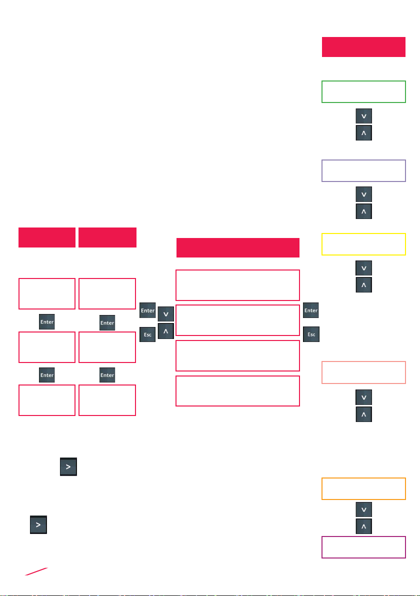
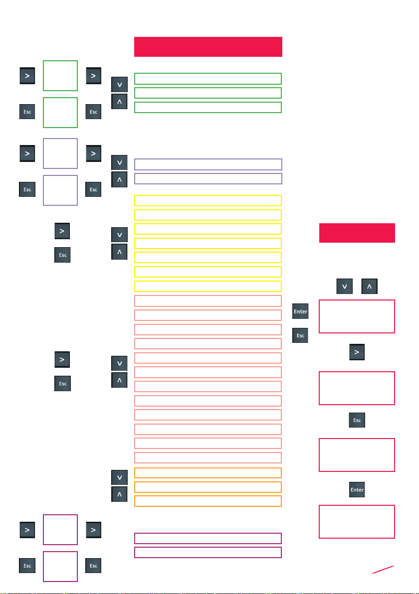
OPERATIONAL
OVERVIEW
The M9.10 Dual Analog Input Monitor and Transmitter
features a full graphic display and a ve-button keypad
for system set-up, calibration and operation. Full graphic
display has a white backlight during standard conditions,
a red backlight in case a set alarm is activated (MAX,
MIN, WINDOW IN, WINDOW OUT MODE: always with
priority), a green backlight in case a external device
control is activated (PROPORTIONAL FREQUENCY,
PROPORTIONAL PULSE, TIMED MODE, ON-OFF MODE)
VIEW LEVEL
MENU DIRECTORY
↓
↓
IN1 - IN2
(Delta IN1-IN2)**
IN 2 – OUT mA 2
IN 1 – OUT mA 1
Output Settings ***
Settings
Calibration
Outputs
Options
View data
Adjust
input mA
* For negative values rstly set the corresponding positive value
and then move the position indicator beyond the last position on
the right using to get the minus sign (not available for ow measurement)
*** for more info about Outputs
**** Use the same Engineering Unit on both INPUTS
** Delta visualization can be activated in Options Menù.
1SSR , 3 RELAY, 4-20 mA 1 can be assigned to the rst input.
2 SSR, 4 RELAY, 4-20 mA 2 can be assigned to the second input.
SET THE
FOLLOWING
PARAMETERS
SET THE
FOLLOWING
PARAMETERS
FIRST INPUT:
CURRENT
SECOND INPUT:
CURRENT
INPUT UNIT INPUT UNIT
INPUT 4 mA* INPUT 4 mA*
INPUT 20 mA* INPUT 20 mA*
↓
↓
11
EDIT LEVEL
PUSH BUTTON
MENU LEVEL
IN LINE-ADJUSTEMENT*
2 POINT CALIBRATION*
RESET STATISTICS
SIGNAL PROBE
OUTPUT STATISTICS
ADJUST INPUT 4 mA
ADJUST INPUT 20 mA
to modify an item
to scroll right
to return to Menu
without saving
to save new settings
↓
↓
↓
↓
INPUT 20 mA*
mA INPUT UNIT
INPUT 4 mA*
↓
↓
1 SSR*
2 SSR*
3 RELAY*
4 RELAY*
4-20 mA 1*
4-20 mA 2*
TEST OUTPUT
↓
↓
↓
↓
INPUT 1
INPUT 2
↓
↓
↓
↓
INPUT 1
INPUT 2
↓
↓
↓
↓
INPUT 1
INPUT 2
LANGUAGE
DECIMAL POINT INPUT 1
FILTER INPUT 1
DECIMAL POINT INPUT 2
FILTER INPUT 2
PASSWORD
BACKLIGHT
OUTPUT ACTIVATION
DELTA IN****
CONTRAST
UPGRADE FIRMWARE
DEFAULT DATA

12
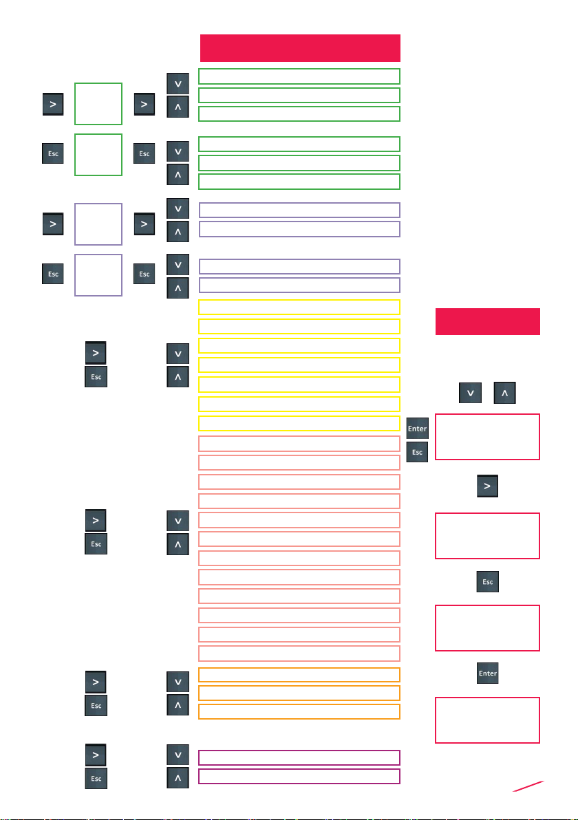
OPERATIONAL
OVERVIEW
The M9.10 Dual Analog Input Monitor and Transmitter
features a full graphic display and a ve-button keypad
for system set-up, calibration and operation. Full graphic
display has a white backlight during standard conditions,
a red backlight in case a set alarm is activated (MAX,
MIN, WINDOW IN, WINDOW OUT MODE: always with
priority), a green backlight in case a external device
control is activated( PROPORTIONAL FREQUENCY,
PROPORTIONAL PULSE, ON-OFF MODE, TIMED MODE).
SET THE
FOLLOWING
PARAMETERS
SET THE
FOLLOWING
PARAMETERS
VIEW LEVEL
FIRST INPUT:
CURRENT
SECOND INPUT:
FREQUENCY
MENU DIRECTORY
↓
↓
↓
↓
IN1 - IN2
(Delta IN1-IN2)**
INPUT UNIT K FACTOR
VALUE(b)
IN 2 – INFINITE TOTALIZER -
RESETTABLE TOTALIZER *
IN 2 – OUT mA 2
IN 1 – OUT mA 1
Output Settings **
INPUT 4 mA(a) FLOW UNIT
INPUT 20 mA(a) VOLUME UNIT
Settings
Calibration
Outputs
Options
View data
Adjust
input mA
* Resettable totalizers can be reset using on view level (only with frequency input).
*** for more info about Outputs
** Delta visualization can be activated in Option Menù.
**** Use the same Engineering Unit on both INPUTS
1 SSR , 3 RELAY, 4-20 mA 1 can be assigned to the rst input.
(b) K factor is value of pulses/liter (available on technical manual of connected FLS
sensor)
2 SSR, 4 RELAY, 4-20 mA 2 can be assigned to the second input.
(a) For negative values rstly set the corresponding positive value and then move the
position indicator beyond the last position on the right using to get the minus sign
(not available for ow measurement)
13
EDIT LEVEL
PUSH BUTTON
MENU LEVEL
to modify an item
to scroll right
to return to Menu
without saving
to save new settings
↓
↓
INPUT 20 mA (a)
mA INPUT UNIT
INPUT 4 mA (a)
K FACTOR VALUE
FLOW UNIT
VOLUME UNIT
↓
↓
↓
↓
IN LINE-ADJUSTEMENT(a)
2 POINT CALIBRATION(a)
CORRECTION FACTOR
AUTO CALIBRATION
1 SSR (a)
2 SSR
3 RELAY (a)
4 RELAY
4-20 mA 1 (a)
4-20 mA 2
TEST OUTPUT
↓
↓
LANGUAGE
DECIMAL POINT INPUT 1
FILTER INPUT 1
DECIMAL POINT INPUT 2
FILTER INPUT 2
PASSWORD
BACKLIGHT
OUTPUT ACTIVATION
UPGRADE FIRMWARE
DELTA FLOW ****
DEFAULT DATA
CONTRAST
↓
↓
RESET STATISTICS
SIGNAL PROBE
OUTPUT STATISTICS
↓
↓
ADJUST INPUT 4 mA
ADJUST INPUT 20 mA
↓
↓
INPUT 1
INPUT 2
↓
↓
↓
↓
INPUT 1
INPUT 2

14
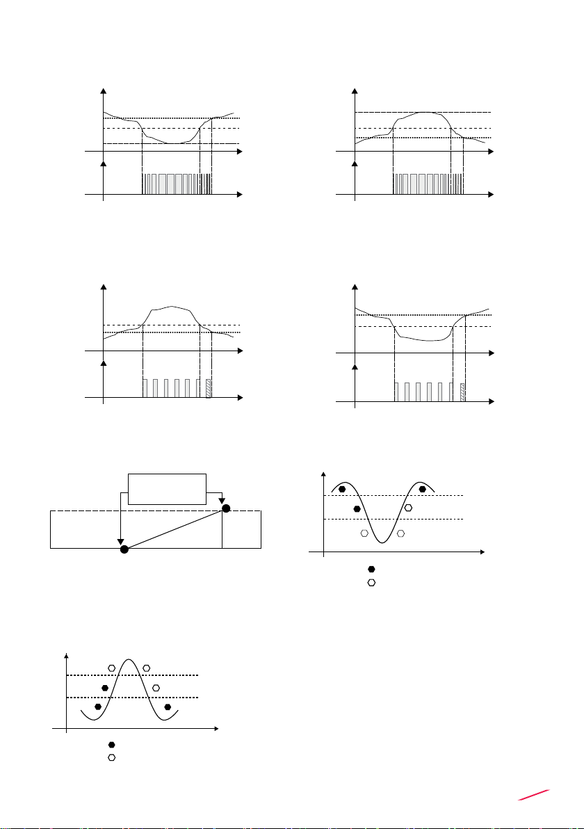
OUTPUT MODE
The M9.10 Dual Analog monitor and transmitter features 2 solid state relays
and 2 mechanical relay in addition to an 2 analog output 4-20mA.
1 SSR , 3 RELAY, 4-20 mA 1 can be assigned to the rst input.
2 SSR, 4 RELAY, 4-20 mA 2 can be assigned to the second input.
PROCEDURE FOR OUTPUTS SETTING
- go to the “Options” menu
- enter into the “Outputs activation” sub menu
- enable output(s)
- go to the “Outputs” menu
- set the operating mode for each enabled output
Digital outputs can be set in the following way:
Monitor without digital
output activated
In case a digital output
is enabled, a icon will
appear
In case a digital output
is set, icon reports the
operating mode
In case set digital
output is activated, the
icon will turn to black
ON-OFF MODE (icon reports O-F)
LOW LEVEL
ON-OFF MODE (icon reports O-F)
HIGH LEVEL
Hysteresis
Setpoint
Output relaxed
Output energized
Cond.
Time
Hysteresis
Setpoint
Output relaxed
Output energized
Cond.
Time
ENT ER T O CONFIGURE
ENT ER T O CONFIGURE
ENT ER T O CONFIGURE ENT ER T O CONFIGURE
1 PRP
15
PROPORTIONAL MODE (icon
reports PRP) LOW LEVEL
TIMED MODE (icon reports TMD)
HIGH LEVEL
FREQUENCY MODE
(icon reports FRQ)
PROPORTIONAL MODE (icon
reports PRP) HIGH LEVEL
TIMED MODE (icon reports TMD)
LOW LEVEL
Set Point I + His
Set Point I
Prop. Band
Relay
Prop
Cond.
Set Point I + His
Set Point I
Cond.
Relay
Timed
Endpoint
100 pulses
from 0 to max
pulses / min
Starting point
0 pulses
5 10
Set Point I + His
Set Point I
Prop. Band
Relay
Prop
Cond.
Set Point I + His
Cond.
Set Point I
Relay
Timed
MIN MODE (icon reports MIN)
MAX MODE (icon reports MAX)
Flow
Time
Hysteresis
Output relaxed
Output energized
Setpoint
Flow
Time
Hysteresis
Output relaxed
Output energized
Setpoint
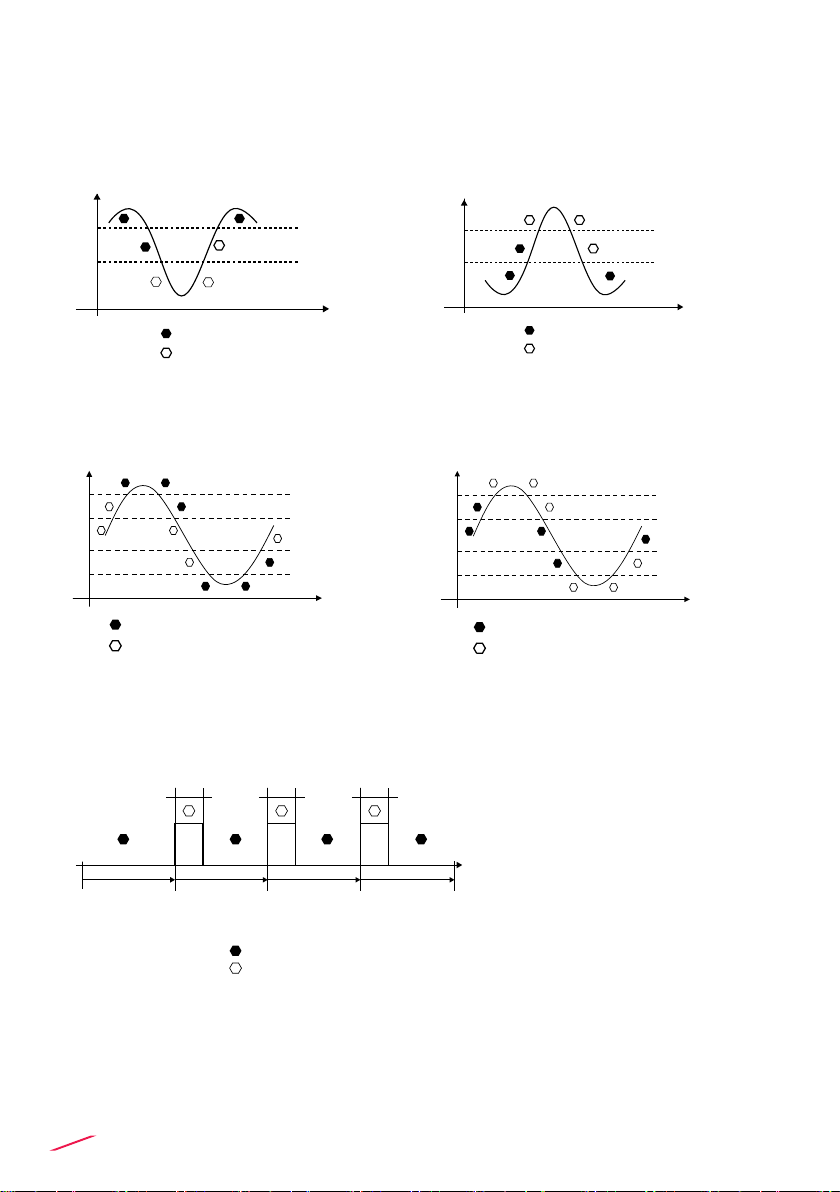
16
In case frequency input is activated, digital outputs (2 SSR, 4 RELAY) can be
set in following way:
MIN MODE (icon reports MIN)
WINDOW IN MODE
(icon reports WIN)
WINDOW OUT MODE
(icon reports WOT)
MAX MODE (icon reports MAX)
PULSE MODE (icon reports PLS)
Flow
Time
Hysteresis
Output relaxed
Output energized
Setpoint
Flow
Time
Hysteresis
Output relaxed
Output energized
Setpoint
Pulse duration
Volume Volume Volume
Pulse duration Pulse duration
Output relaxed
Output energized
Output relaxed
Output energized
Time
Flow
Hysteresis
Setpoint
Setpoint
Hysteresis
Flow
Time
Hysteresis
Output relaxed
Output energized
Setpoint
Output relaxed
Output energized
Time
Flow
Hysteresis
Setpoint
Setpoint
Hysteresis
Output relaxed
Output energized
Time
Flow
Hysteresis
Setpoint
Setpoint
Hysteresis
Output relaxed
Output energized
Time
Flow
Hysteresis
Setpoint
Setpoint
Hysteresis
Output relaxed
Output energized
Time
Flow
Hysteresis
Setpoint
Setpoint
Hysteresis
Flow
Time
Hysteresis
Output relaxed
Output energized
Setpoint
Output relaxed
Output energized
Time
Flow
Hysteresis
Setpoint
Setpoint
Hysteresis
Output relaxed
Output energized
Time
Flow
Hysteresis
Setpoint
Setpoint
Hysteresis
Output relaxed
Output energized
Time
Flow
Hysteresis
Setpoint
Setpoint
Hysteresis
Output relaxed
Output energized
Time
Flow
Hysteresis
Setpoint
Setpoint
Hysteresis
Output relaxed
Output energized
Time
Flow
Hysteresis
Setpoint
Setpoint
Hysteresis

17
SOFTWARE UPDATING
In order to update the Instrument Software with a New Firmware Release
follow the suggested procedures
TO UPDATE INSTALLED UNITS
- Download the interface software “FLS Calibration System”
and the Updated Software on www.snet.it
- Launch the software "FLS Calibration System" on the laptop
- Select OPTION and then UPGRADE FIRMWARE
- Conrm the "Firmware Upgrade" procedure by ENTER
- Connect M9.10 to the laptop by the USB cable
- Select the item which appears on NAVIGATION area
on the "FLS Calibration System" software
- Conrm FW UPGRADE and select the Updated Software
NOTE: At the end of the procedure restart the instruments in order to refresh
M9.10 software (It takes 90 seconds to refresh the SW. Please do not interrupt
the restarting process).
TO UPDATE NEW UNITS
- Download the interface software “FLS Calibration System”
and the updated software on www.snet.it
- Launch the software "FLS Calibration System" on the laptop
- Push together ENTER and ESC powering the monitor
- Connect M9.10 to the laptop by the USB cable
- Select the item which appears on the NAVIGATION
area on the software "FLS Calibration System"
- Conrm FW UPGRADE and select the Updated Software
NOTE: At the end of the procedure restart the instruments in order to refresh
M9.10 software (It takes 90 seconds to refresh the SW. Please do not interrupt
the restarting process).

18
ORDERING DATA
Part No. Description
/Name
Power
supply
Wire power
Technology
Sensor
Input Output
M9.10.P1
Panel
mount Dual
Parameter
Analog
monitor &
transmitter
12 - 24 VDC 3/4 wire 2 * 4-20mA
2*(4-20mA),
2*(S.S.R.),
2*(mech. relay)
M9.10.W1
Wall mount
Dual-
Parameter
Analog
monitor &
transmitter
12 - 24 VDC 3/4 wire 2 * 4-20mA
2*(4-20mA),
2*(S.S.R.),
2*(mech. relay)
M9.10.W2
Wall mount
Dual-
Parameter
Analog
monitor &
transmitter
110 - 230 VAC 3/4 wire 2 * 4-20mA
2*(4-20mA),
2*(S.S.R.),
2*(mech. relay)
ACCESSORIES
SPARE PARTS
Part No. Name Description
M9.KW1 Wall mounting kit 144x144mm plastic box for wall installation
of all panel mount monitors
M9.KW2 Wall mounting kit with
power supply
144x144mm plastic box and 110/230VAC to 24 VDC power
supply for wall installation of all panel mount monitors
M9.KUSB USB cable for device
interfacing USB cable dedicated to FLS products, 1,5 meter long
Part No. Name Description
M9.SN1 Fixing snails 2 xing snails for panel installation of FLS monitors

19
NOTE

FIP - Formatura Iniezione Polimeri S.p.A.
Loc. Pian di Parata
16015 Casella
Genova - Italy
Tel. +39 010 96211
Fax +39 010 9621209
www.flsnet.it
I2374 IMM910E REV-01 - 12/2016
Table of contents
Other FIP Transmitter manuals


Popular Transmitter manuals by other brands

Huato
Huato HE200 Series Operational manual

GTO
GTO SW2002XLS instructions

Rosslare
Rosslare SA-26 installation instructions

Greystone Energy Systems
Greystone Energy Systems GDT Series installation instructions

Visonic
Visonic TOWER 10 AM - installation instructions

MK
MK K5786 Installation & operating instructions


Intelix
Intelix DIGI-VGASD2-T8 installation guide

Nice
Nice P1I/U Instructions and warnings for installation and use

ADEMCO
ADEMCO 5817 installation instructions

Honeywell
Honeywell XNX Universal Transmitter installation guide

LYNXTechnik
LYNXTechnik Yellobrik OTX 1712 quick reference

VARIZOOM
VARIZOOM VZ-WFF instruction manual