Huato HE200 Series Quick start guide

Operational manual of universal temperature
humidity transmitter
HE200 Series HE400 Series

--------P.1--------
Introduction:
HE400 series and HE200 series are temperature, relative humidity transmitters, adopt import
components and high-performance low-power SCM design, which assure the quality and stability. HE400
series and HE200 series support two kinds of output, Voltage and Current. They have unique design
features to ensure no circuit interface of themselves. They are wall-mounted and enjoy widely measuring
range and high accuracy, suitable for DC16V-30V. HE400 series has LCD display, HE200 series has no
LCD display. Besides, both of them have internal and external probe. Customers can have many choices
according to their demands.
Applications:
HE400 series and HE200 series are designed for temperature and humidity control in conditioning and
ventilation application in the following sectors: pharmacy, museums, clean rooms, ventilation ducts,
industrial and civil sectors, crowded places, canteens, auditoria, gyms, high-density farms, greenhouse, etc.
Model list:
Model HE200A HE200A-EX HE200V5 HE200V5-EX HE200V10 HE200V10-EX
HE400A HE400A-EX HE400V5 HE400V5-EX HE400V10 HE400V10-EX
Temperature accuracy ±0.5℃ ±0.5℃ ±0.5℃ ±0.5℃ ±0.5℃ ±0.5℃
Humidity accuracy ±3%RH ±3%RH ±3%RH ±3%RH ±3%RH ±3%RH
Sensor type Internal External Internal External Internal External
Measuring range 0~50℃ -30~70℃ 0~50℃ -30~70℃ 0~50℃ -30~70℃
Output 4~20mA 4~20mA 0-5V 0-5V 0-10V 0-10V
Wire mode 3 lead terminals 4 lead terminals
Measuring range 0~100%RH
Mechanical drawings:
The port of external sensor
HUATO
External sensor size:
L=3m(standard accessories)
L=5m(optional accessories)
D1=16mm(0.63")
D2=10mm(0.39")

--------P.2--------
Technical specifications:
Temperature Humidity
Measuring
range 0℃~50℃(internal)
-30℃~70℃(external)
0%RH~100%RH
temperature
accuracy ±0.5℃ ≤±3%RH(25℃,20-90%RH)
Working
range
-10℃~60℃ 0%RH~100%RH(non-condensing)
Power
supply
DC16~30V (suggest 24V)
Output Voltage 0~5V / 0-10V Current 4-20mA
Canning
material
ABS Engineering Plastics
Wire mode Voltage 4 lead terminals Current 3 lead terminals
Look-up table for analog output:
0-5V 0-10V 4~20mA
Humidity 0%RH 0 0 4mA
100%RH 5v 10v 20mA
Temperature 0℃ (-30) 0 0 4mA
50℃ (70) 5v 10v 20mA
Order of connection for voltage:
1 2 3 4 5 6
T_out RH_out Gnd VCC
Temperature output Humidity output Negative wire Positive wire
Order of connection for current:
1 2 3 4 5 6
T_out RH_out VCC
Temperature output Humidity output Positive wire
Installation instructions:
Fist fix the drain pan onto the right installation position,then buckle the watch case upon the installed
drain pain.

--------P.3--------
Button instructions:
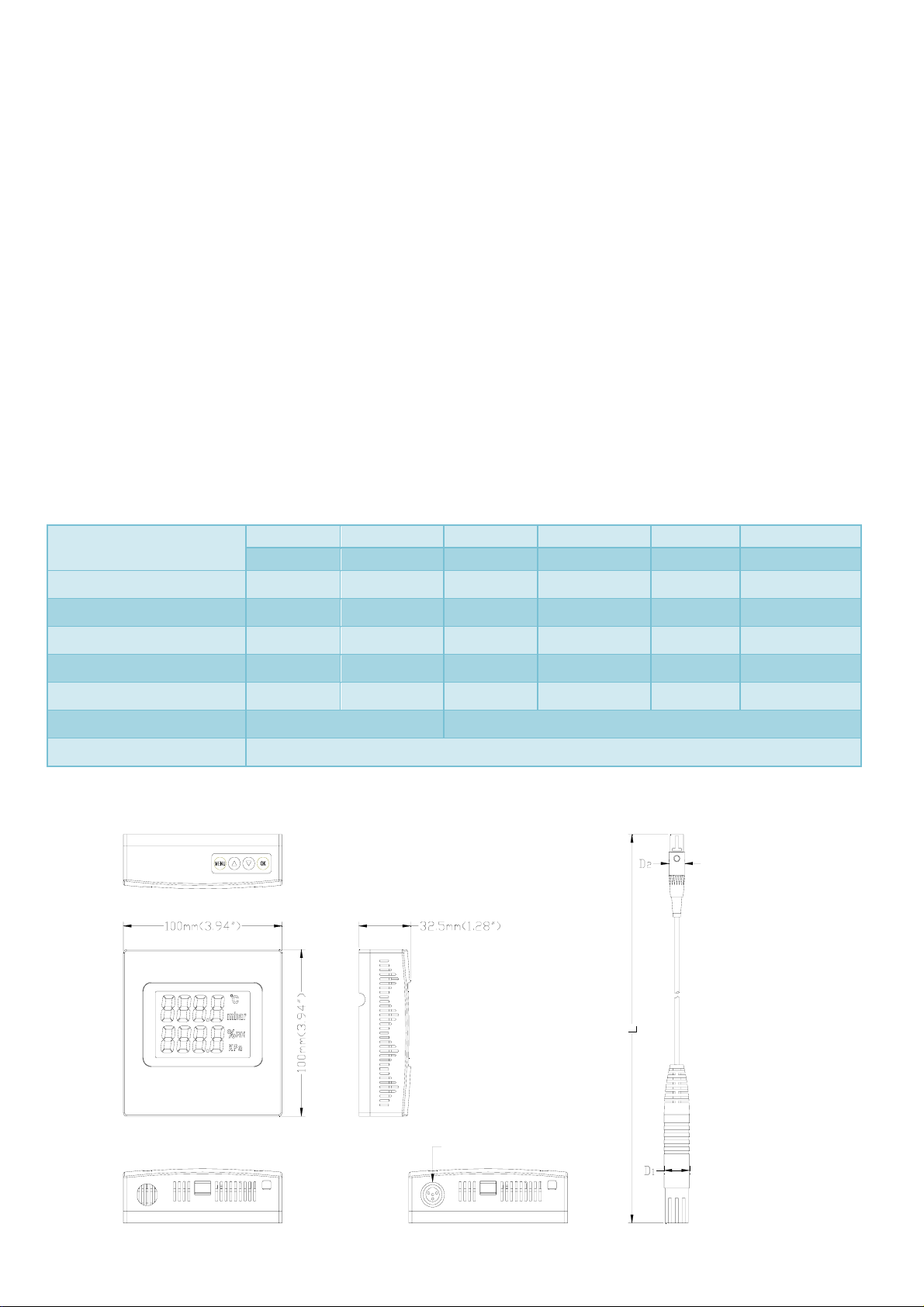
There are 4 buttons: , that is MENU, UP, DOWN and OK key. Key functions as follows:
Name MENU UP DOWN OK
Functions Set key Up key Down key Ok key
Press the MENU key for 3 to 5 seconds long enough to enter setting menu, appear SET and press OK to
enter selecting mode menu, then it will appear 1-5 numbers, one number to one mode as follows:
1 Single temperature output mode,it only displays temperature and
temperatureoutputsignalunderthiskindofmode.
2 Singlehumidityoutputmode,itonlydisplayshumidityandhumidity
outputsignalunderthiskindofmode.
3 Set temperature linear calibration mode ,usedforcalibrating
temperature.
4 Sethumiditylinearcalibrationmode,usedforcalibratinghumidity.
5 Normalworkingmode,itdisplays both temperature and humidity
outputsignal.
Notice under single temperature or single humidity output:
LCD will display temperature or humidity value as well as temperature or humidity output signal (4-20ma)
under single mode. At the same time, please connect the unused pin to the VCC to make sure the output
signal is correct.
Two steps for temperature linear calibration setting:
zEntering into temperature linear calibration mode (press MENU and number 3), press OK to enter
temperature range 75% calibration point. That is the current environment temperature should be 45℃,
till temperature is stable (about 30mins or more), then transmitter LCD will display two-line values. The
first line displays the testing temperature U1, the second line displays 45.0. Now you can choose UP
and DOWN keys to calibrate the U1 to 45℃and then click OK key to confirm. So transmitter can
record the offset value under temperature of 45℃.
zThen entering into temperature range 33% calibration point, that is the current temperature should be
3℃. Transmitter LCD will display two-line values after the temperature is stable (about 30mins or
more). The first line displays the testing temperature U2, the second line displays 3.0. Now you can
choose UP and DOWN keys to calibrate the U2 to 3℃and click OK key to confirm so that the

--------P.4--------
transmitter can record the offset value under temperature of 45℃.After these two steps calibration, the
output value will be the correct one.
Two steps for humidity linear calibration setting:
zEntering into humidity calibration mode (press MENU and number 4), press OK to enter humidity
range 75% calibration point. That is the current humidity should be 75%. Transmitter LCD will display
two-line values after the humidity is stable (about 30mins or more). The first line displays the testing
humidity U1; the second line displays 75%. Now you can choose UP and DOWN keys to calibrate the
U1 to 75% and click OK key to confirm so that the transmitter can record the offset value under
humidity of 75%.
zThen entering into humidity range 33% calibration point, that is the current environment humidity
should be 33%. Transmitter LCD will display two-line values after the humidity is stable (about 30mins
or more). The first line displays the testing humidity U2; the second line displays 33%. Now you can
choose UP and DOWN keys to calibrate the U2 to 33% and click OK key to confirm so that the
transmitter can record the offset value under humidity of 33%. After these two steps calibration, the
output value will be the correct one. Now you can back to the normal working mode and both of the
value is correct.
Quality assurance :
Instrument warranty for 1 year, our factory is responsible for non-man-made damage during
maintenance period.
Notes :
1.Please avoid direct sunlight and any situation which may influence the accuracy of temperature and
humidity surrounding the installation position.
2.Please shut off the power supply before installation and replacement. Besides, please check the
connection to assure whether it is right before power up.
3.Some functional parameters of product maybe amended, the correct functional parameter is subject to
the label.
HUATO Electric (Shenzhen) Co., Ltd
Address: F3 of Building 1, Taohuayuan Technological Innovation Zone, Xixiang Street, Baoan District, Shenzhen, China.
After-sales service hotline:0086-755-29977880 Fax:0086-755-29748856 Website:http://www.huatos.com
This manual suits for next models
13
Table of contents
Other Huato Transmitter manuals
Popular Transmitter manuals by other brands

TE-Group
TE-Group mr Handsfree FM201 Quick reference guide

Intelbras
Intelbras TX 4020 Smart user manual

WaveIP
WaveIP GigAccess RSU900 End user manual

Emerson
Emerson Rosemount 3144P Reference manual

Inovonics
Inovonics FA214 installation instructions

Silicon Laboratories
Silicon Laboratories Si4704 Series Programming guide