Fire dept GD12 Series User manual

GD12 –Remote Control
Installation Guide
Operating Instructions
Warranty

Version: August 2020 2
GD12 Installation Guide, Operating Instructions & Warranty
IMPORTANT!
This gas appliance must be installed to AS/NZS 5601.1:2013 by a qualified person and in accordance with
these instructions. Failure to install the appliance correctly will void your warranty and may cause a fire. This
appliance should not be modified under any circumstances.
Under no circumstances should any combustibles such as paper, wood or coal be used in this appliance.
It is recommended that you have this appliance serviced annually by a qualified technician.
Warranty repairs must be carried out by a ‘The Fire Dept.’ authorised technician.
This appliance must ALWAYS terminate/flue outdoors.
Young children, elderly or infirm should be supervised to ensure that they are careful with the appliance.
Clothing and other flammable materials should never be placed near the appliance.
Never switch the appliance on without the glass in place.
Please note that parts (near the flame) of this appliance, particularly the steel surrounding, glass panels to the
face or the door, become extremely hot during operation and can result in serious injury and burns if touched. It
is therefore recommended that a fireguard complying with BS 8423:2002 is used in the presence of young
children, the elderly or infirm.
The GD12 installation process consists of 8 steps Page
Step 1: Unpack and ensure all components are correct and undamaged 3
Step 2: Install plinth (if required) 3
Step 3: Install appliance into cavity 3
Glass removal process 4
Glass installation process 5
Burner Tray Removal Process 6
Burner Tray Installation Process 7
Step 4: Install flue, Air supply (duct and bracket) and connect to appliance 9
Step 5: Connect and test electrical supply 16
Step 6: Connect gas supply and commission 18
Step 7: Lay the firebed 19
How to lay River Rocks Firebed - GD12 1200 22
How to lay River Rocks Firebed - GD12 1400 & 1600 23
How to lay Beach Driftwood Firebed - GD12 1200 24
How to lay Beach Driftwood Firebed - GD12 1400 & 1600 25
How to lay Forest Logs Firebed - GD12 1200 26
How to lay Forest Logs Firebed - GD12 1400 & 1600 27
Step 8: Show owner how to operate appliance 28
GD12 Operating instructions 29
Troubleshooting 35
Product warranty 36
Information in this installation guide may be subject to change without notice.
Please ensure that you have the current version before beginning installation.
Version: August 2020 3
Step 1: Unpack and ensure all components are correct and undamaged
•Appliance with 2 remote controls (one spare)
•Box of firebed mediums
•Flue kit
Step 2: Install plinth (if required)
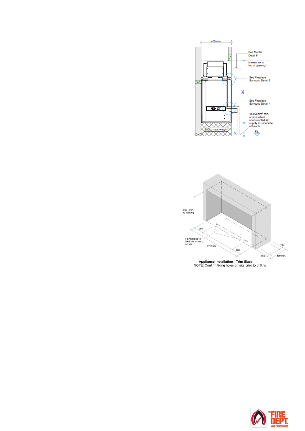
•If the appliance is to sit on a plinth, ensure it is capable of
supporting a 200kg load.
•There is no clearance requirement for the base of the appliance.
It may safely sit directly upon combustible (eg. timber)
and non-combustible (eg. concrete) materials.
Step 3: Install appliance into cavity
•Before installation, confirm all minimum clearances
from the outside surfaces of the appliance to the surrounding
enclosure are no closer than 25mm from combustible
materials and 5mm from non-combustible materials.
•The exception to these minimum clearances is the base
and the outer 2mm steel perimeter panels of the appliance, the
base can safely sit directly upon combustible (eg. timber)
and non-combustible (eg. concrete) materials. The outer
2mm steel perimeter panels and rear air channel can safely
touch combustible (eg. timber) and non-combustible
(eg. concrete) materials.
•If a gas supply pipe has already been run to the cavity, ensure 1000mm of 3/8 soft copper tube is available
at the lower side of the cavity, as this is where the copper tube with the gas supply enters the appliance.
•If an electrical supply cable has already been run to the cavity (must be a minimum of 1.0mm 3 core cable),
ensure that the cable reaches the lower side of the cavity, as this is where it will enter the appliance.
•In order to access the fixing slots in the base of the appliance, and the gas and electrical connections, it is
necessary to first remove the glass and the burner tray.

Version: August 2020 4
Glass removal process
•Note: Glass removal is best carried out by two people.
•Carefully remove glass, which is held in place by retaining clips along the top of the glass and powerful
magnets in each lower corner.
•Remove the top retaining clips by undoing the 4mm Allen head
cap screws.
•Gently pull at the top corners in a forward motion. The glass will
tilt forward.
•In one movement gently pull the glass up and away from the appliance to break the magnetic connection.
Take care that the glass doesn't fall completely off once it’s free from the fixing magnets.
•Lift glass away from the appliance and lay flat in a safe place with insulating material facing down to
protect glass.
Version: August 2020 5
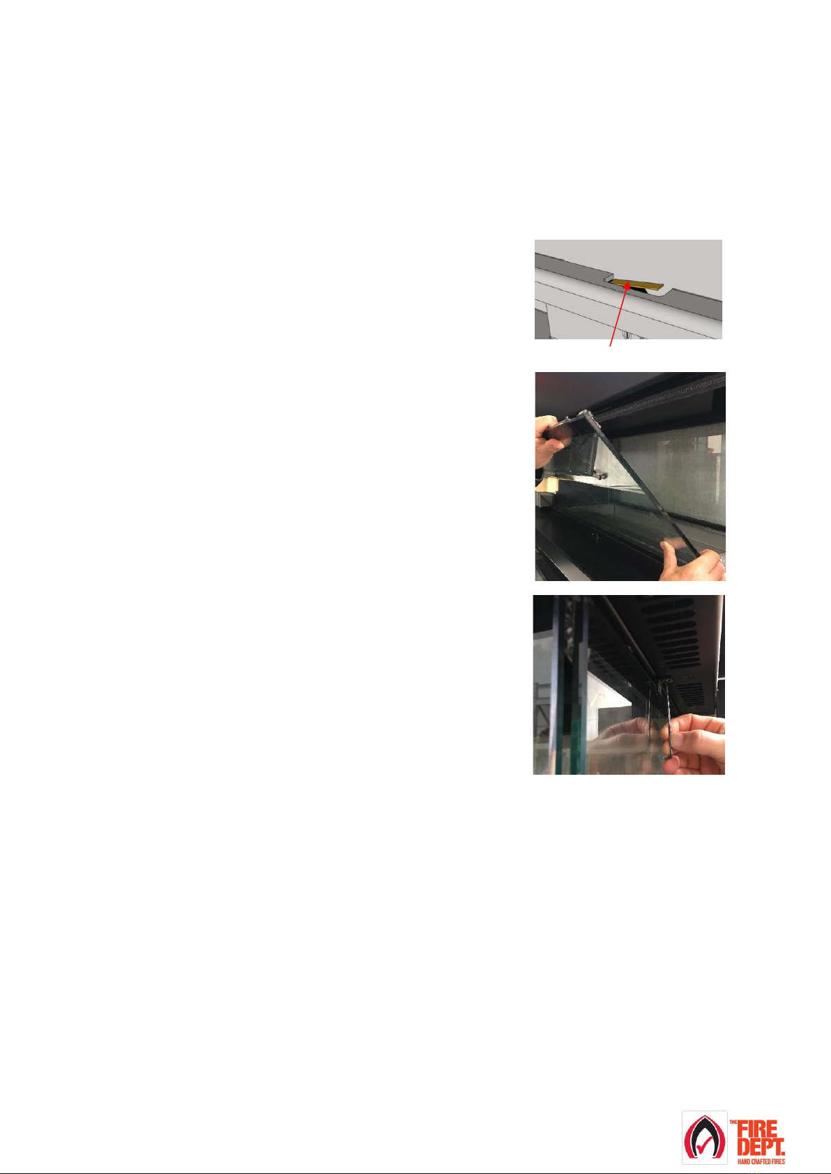
Glass installation process
•Note: Glass installation is best carried out by two people. Check all glass edges and surfaces for damage.
Do not install the glass if it is damaged. Check that the insulating material (ladder rope around the outer edge
of the glass and around the opening of the appliance) is complete and undamaged. Do not install the glass if
the insulating material is damaged or missing.
•Carefully install the glass, which is held in place by retaining clips along the top of the glass and powerful
magnets in each lower corner.
•On the back corner of each glass there are 3mm steel magnet
panels. In one movement, gently lower the glass down allowing the
steel magnet panels to catch the top front face of the magnets.
Take care lowering the glass completely down into position. The
glass will lower onto a safety switch. There is a safety switch at the
base of each glass panel.
•Gently push the top corners of the glass back into position.
•Tighten the 4mm cap screws that hold the glass retaining clips in
position.
Make sure the retaining clips sit flat onto the glass surface.
Safety switch

Version: August 2020 6
Burner Tray Removal Process
Cover and end cap removal
GD12 Pilot cover
This model has one pilot
cover.
•Remove the stainless steel pilot cover (2 x
screws) at the pilot end of the burner.
GD12 Burner end caps
This model has two end
cap covers, one at each
side of the burner.
•Remove the stainless steel burner end caps
(3 x screws on each cap) at either end of the
burner tray.
LPG
Natural Gas
GD12 1200
Input 18-28 MJ/h
One gas injector at the pilot
side of the burner tray.
•Remove the burner tray by carefully pushing
it away from the pilot and lift the pilot end of
the burner tray, lift the burner tray up and
away from the pilot in one movement.
•Stand the burner tray on its end and lean
against a stable surface.
•Remove the burner tray by carefully pushing it away from the
pilot and lift the pilot end of the burner tray, lift the burner tray up
and away from the pilot in one movement.
•Stand the burner tray on its end and lean against a stable
surface.
GD12 1400
Input 20-28 MJ/h
Two gas injectors one at the
right and one at left hand
sides of the burner tray.
GD12 1600
Input 30-38 MJ/h
Two gas injectors one at the
right and one at left
•Remove the burner tray by carefully pushing
it away from the pilot and lift the pilot end of
the burner tray, lift the burner tray up and
away from the pilot in one movement. Ensure
that the gas injector at the left hand side is
not damaged as the burner tray is lifted out.
•Stand the burner tray on its end and lean
against a stable surface.
•On the pilot side gas injector, loosen and spin back the 12mm
brass nut away from the burner tray.
•On the non-pilot side injector, loosen both the 12mm brass nuts
all the way to the end of the injector. The injector will need to be
pushed away from the burner tray.
•Remove the burner tray by carefully pushing it away from the
pilot and lift the pilot end of the burner tray, lift the burner tray
up and away from the pilot in one movement.
•Stand the burner tray on its end and lean against a stable
surface.
Pilot side Gas Injector
Non-pilot side Gas Injector
Pilot burner end
cap
Non pilot burner end
cap

Version: August 2020 7
Burner Tray Installation Process
LPG
Natural Gas
GD12 1200
Input 18-26 MJ/h
One gas injector at the
pilot side of the burner tray.
•Install the burner tray by carefully lowering
the end opposite from the pilot meanwhile
holding up the pilot end, lower the burner tray
down and move towards the pilot in one
movement.
•Ensure the burner tray is located correctly
into the burner bracket and the jets are
aiming into the burner tube inlet holes.
•Install the burner tray by carefully lowering the end opposite
from the pilot meanwhile holding up the pilot end, lower the
burner tray down and move towards the pilot in one movement.
•Ensure the burner tray is located correctly into the burner
bracket and the jets are aiming into the burner tube inlet holes.
•On the pilot side gas injector, gently tighten (do not over tighten)
the 12mm brass nut closest to the burner tray.
GD12 1400
Input 20-28 MJ/h
Two gas injectors one at the
right and one at left hand
sides of the burner tray.
GD12 1600
Input 30-38 MJ/h
Two gas injectors one at the
right and one at left hand
sides of the burner tray.
•Install the burner tray by carefully lowering
the end opposite from the pilot meanwhile
holding up the pilot end, lower the burner tray
down and move towards the pilot in one
movement.
•Ensure the burner tray is located correctly
into the burner bracket and the jets are
aiming into the burner tube inlet holes.
•Install the burner tray by carefully lowering the end opposite
from the pilot meanwhile holding up the pilot end, lower the
burner tray down and move towards the pilot in one movement.
•Ensure the burner tray is located correctly into the burner
bracket and the jets are aiming into the burner tube inlet holes.
•On the non pilot side injector, gently tighten both the 12mm
brass nuts. The injector will pull towards the burner tray.
•On both the non-pilot and pilot side gas injectors, gently tighten
(do not over tighten) the 12mm brass nuts closest to the burner
tray.
Cover and end cap installation
GD12 Pilot ladder rope
This model has ladder rope
under the pilot end burner
end cap.
•Ensure the insulating material is glued to the
end cap fixing panel and runs behind the 3
way pilot, rectifier and sparker probes.
GD12 Pilot cover
This model has one pilot
cover.
•Replace the stainless steel pilot cover (2 x
screws) at the pilot end of the burner.
GD12 Burner end caps
This model has two end cap
covers, One at each side of
the burner
•Replace the stainless steel burner end caps
(3 x screws on each cap) at either end of the
burner.
Non-pilot side Gas Injector
Pilot side Gas Injector
Non pilot burner
end cap
Pilot burner end
cap
Insulating material
Pilot cover

Version: August 2020 8
•Slide appliance into position and ensure that it complies with the minimum clearances required (25mm for
combustibles, 5mm for non-combustibles) to the appliance inner panels and 5mm surrounding enclosure.
•The exception to these minimum clearances is the base and the outer 2mm steel perimeter panels of the
appliance, the base can safely sit directly upon combustible (eg. timber) and non-combustible (eg. concrete)
materials. The outer 2mm steel perimeter panels and rear air channel can safely touch combustible (eg.
timber) and non-combustible (eg. concrete) materials.
•In order to provide maximum positioning flexibility, the base has four 30mm long slots.
•Mark out and drill fixing holes through the 30mm slots in the base. Ensure holes are drilled in the centre of
the slots to allow maximum positioning flexibility. Clear out any debris from drilling.
•Ensure the appliance is level and pack up corners to suit where necessary. Fix bolts / screws into floor.
Check and ensure unit is levelled.
•If the electrician and/or gas fitter is available at this stage the electrical supply and gas supply can be
connected and tested / commissioned (see steps 5 & 6).
•Install the burner tray. The burner tray installation process depends upon the model and type of gas to be
used. Refer to table above.

Version: August 2020 9
Step 4: Install flue, Air supply (duct and bracket) and connect to appliance
•Flue installation must meet the requirements of AS/NZS 5601.1:2013 and comply with all local council
requirements and be installed and certified by a suitably qualified person.
•Refer to appropriate ‘The Fire Dept’ product specifications for specific minimum requirements.
•Only follow the ‘Wall cowl assembly details’ in this guide if the flue is to be terminated through a wall.
•A 25mm clearance from combustible materials, 75mm clearance from wiring and plastic pipes and a
minimum of 5mm from non-combustible materials is required when installing a flue system for any appliance
supplied by ‘The Fire Dept.’.
•The flue installation requires a restriction free cavity from the top of the firebox (flue spigot) to the outside
atmosphere.
•For the In-Line fan installation follow the ‘In-Line Fan assembly details’in this guide.
•For all other Cowl Termination options refer to ‘Air supply duct options for the different cowl
terminations’ in this guide.
•Air flow must be unobstructed from the firebox to the inner flue and from the heat shield to outer casing
allowing air to circulate from the firebox to the flue casings to the atmosphere.
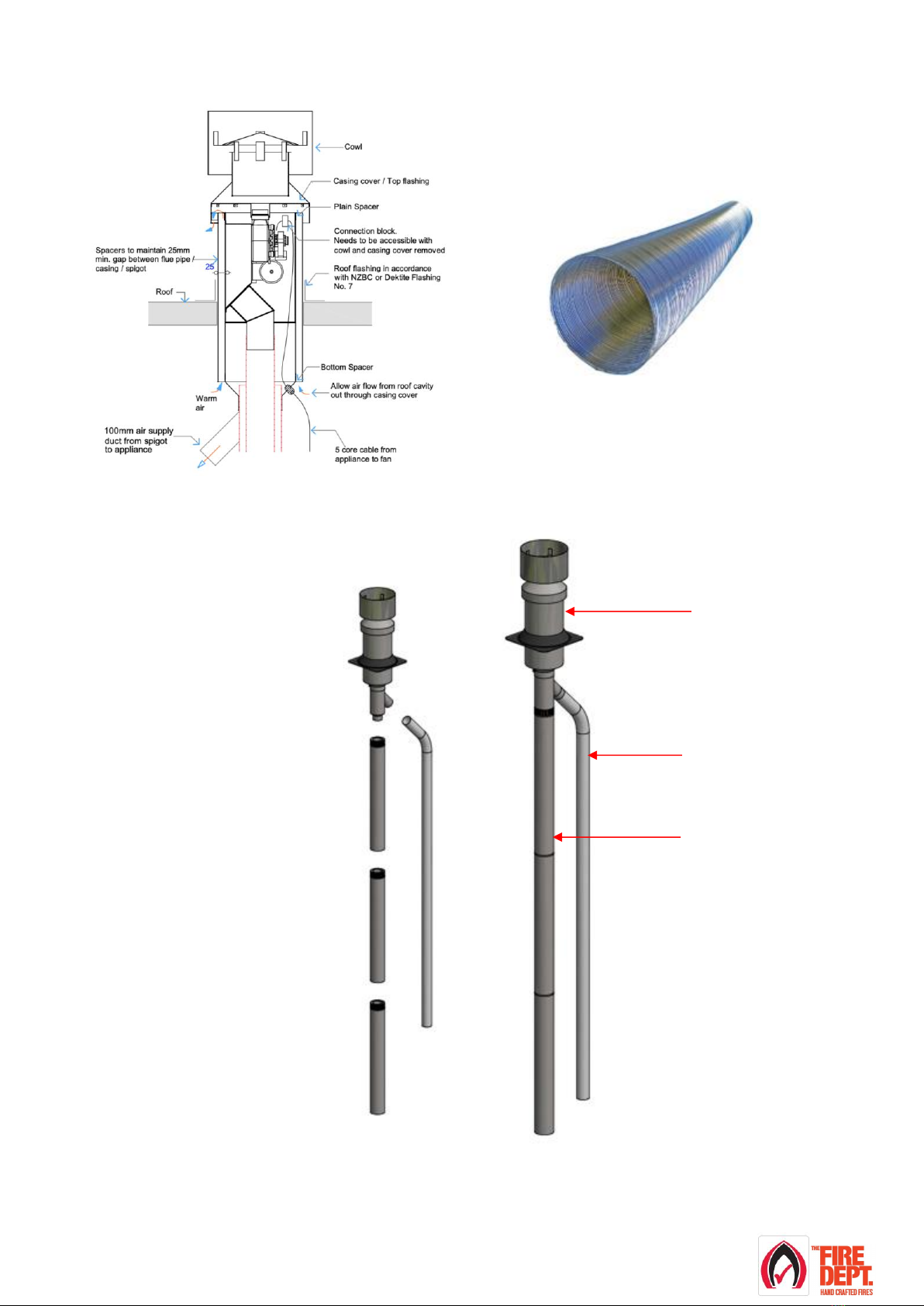
•Connect the Air supply duct bracket to the flue / wall spigot at the flue penetration to termination.
•Run the 100mm Aluminium Semi-Rigid Ducting from the Air supply duct bracket to the 100mm air
supply spigot on the top of the firebox. Refer to appropriate ‘The Fire Dept.’ product specification for
specific fixing requirements.
•The 100mm Aluminium Semi-Rigid Ducting will require a joint if the flue run is over 6 metres. Refer to
appropriate ‘The Fire Dept.’ product specification for specific fixing requirements.

Version: August 2020 10
Flow from the In-Line Fan to termination
In-Line Fan
Casing slip
In-Line Fan assembly details
Step 1:
Connect the flue and outer casing to the appliance
1. Make sure the In-line Fan has adequate access for future maintenance.
2. Run the flue from the appliance to the location of the In-line Fan.
3. Run the outer casing from the appliance to finish 90mm shorter than the flue.
Note: The outer casing must have the crimped end removed.
Step 2:
Connect the In-Line Fan to the flue and outer casing
1. Fit the Casing slip over the outer casing.
2. Fit the flue over the inlet spigot to the In-Line Fan.
3. Fix the flue to the inlet spigot at the In-Line Fan.
Step 3
Complete the flue installation
1. Slide the casing slip up the outer casing and over the outer casing spigot
at the In-Line Fan.
2. Fix the casing slip to the outer casing and the In-Line fan
3. Complete the flue installation. Refer to appropriate Fire Dept product
specification for fixing details and specific minimum requirements.

Version: August 2020 11
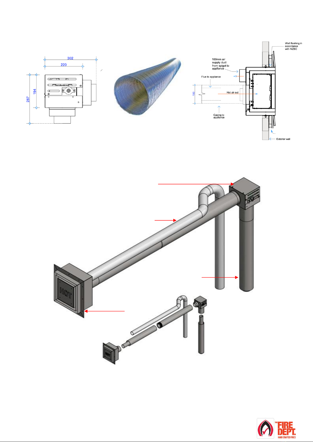
Air supply duct options for the different cowl terminations
Option 1: Wall cowl fan (horizontal exit)
Wall cowl fan: Horizontal exit
100mm Semi-Rigid Duct. 3m or 6m
Wall cowl
100mm Semi-
Rigid Duct
Flue system
F74 –3.6m Flue Wall cowl fan shown
Version: August 2020 12
Option 2: Cowl fan (vertical exit)
Cowl fan: Vertical exit
100mm Semi-Rigid Duct. 3m or 6m
100mm Semi-
Rigid Duct
Flue system
Cowl fan
F75 –3.6m Flue Cowl fan shown

Version: August 2020 13
Option 3A: In-Line Fan (vertical exit)
In-line fan
100mm Semi-Rigid Duct. 3m or 6m
Vertical exit
100mm Semi-
Rigid Duct
Flue system
Vertical exit
In-Line Fan
F76 –3.6m Flue In-Line Fan shown
Version: August 2020 14
Option 3B: In-Line Fan (horizontal exit)
In-line fan
100mm Semi-Rigid Duct. 3m or 6m
Horizontal exit
100mm Semi-
Rigid Duct
Flue system
In-Line Fan
Wall cowl
F77 –3.6m Flue In-Line Fan shown
Version: August 2020 15
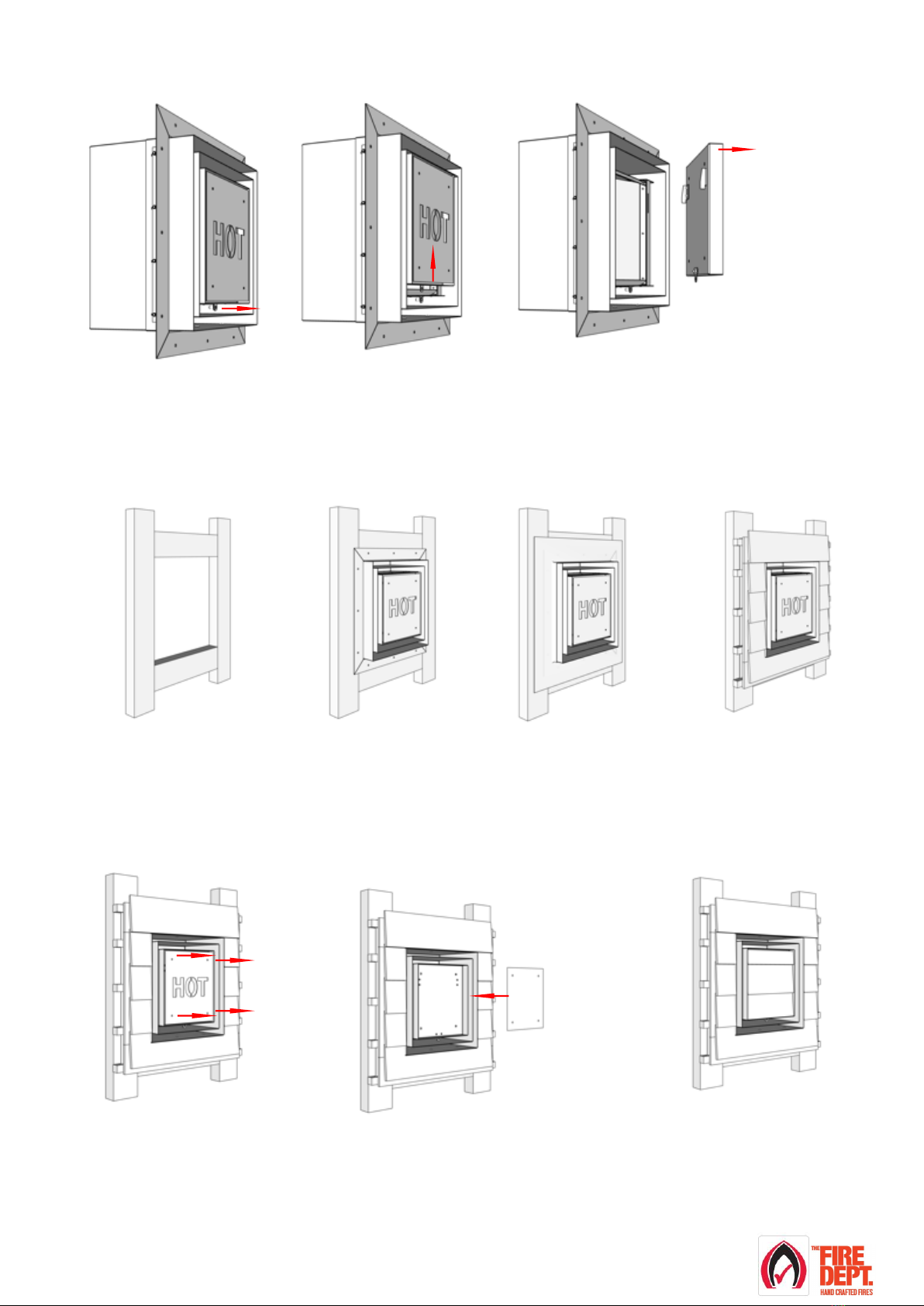
Wall cowl assembly details
(for wall cowl + wall cowl fan installation)
Step 4:
Fit the front
panel
To fit the front
panel reverse
steps 1 to 3
Step 1:
Remove 5mm cap screw
Step 2:
Lift front panel
The front panel is hung on hocks
Step 3:
Remove the front panel
Fit Wall cowl into position
Step 1:
Timber framing
Set-up timber framing to suit
wall cowl.
Step 2:
Fit wall cowl into position
Fix will cowl into position
through the angle surround.
Step 3:
Flash wall cowl
Fit flashing in
accordance with NZBC.
Step 4:
Complete wall cladding
Fit wall cladding in accordance
with NZBC
Fit wall cladding into Wall cowl front panel (optional)
Step 1:
Remove front hot panel
1. Hot panel is fixed to back
panel with 4 x 5mm
counter-sunk cap screws.
Step 2:
Fix sub-straight into wall cowl
1. Cut sub-straight to suit (sub-straight not supplied)
2. The 4 x 5mm counter-sunk cap screws can be
used to hold the sub-straight in place.
Step 3:
Fix cladding into wall cowl
1. Adequately fix the cladding into the
wall cowl.

Version: August 2020 16
Step 5: Connect and test electrical supply
•All electrical connections must meet the requirements of AS/NZS 3000 standards and be installed
and certified by a suitably qualified person.
•In order to access the electricals, it is necessary to first remove the glass and the burner tray.
•Follow the ‘Glass installation process’ in this guide.
•Lift glass away from the appliance and lay flat in a safe place with insulating material facing down.
•Remove the burner tray by following the ‘Burner Tray Removal Process’in this guide.
•With the burner tray removed the electrical connections between the appliance and the wall isolation switch
can be seen, use 3 core (minimum 1mm) cable from the wall isolation switch.
•Following these connection details, using the 3 core cable that has been run at site, connect the wall
isolation switch to the appliance
•IMPORTANT: Before testing, ensure the gas valve is
turned OFF.
•The GD12 models have for each glass panel a safety
switch, at the base of each lower opening. The safety
switch turns the appliance off if the glass is not in the right
position. The safety switch will need to be held down to
complete electrical testing. It is recommended that
masking tape is used to hold the safety switch down.
•Test electrical functions by switching the wall isolation switch to the appliance ON.
•Using the remote control, switch the appliance ON, following the ‘GD12 Operating Instructions’ in this
guide.
•The fan will start and after approximately 25 seconds, the pilot will spark. Because the gas supply is turned
off, the pilot will spark for approximately 25 seconds then automatically switch off.
•Using the remote control switch the appliance OFF, following the ‘GD12 Operating Instructions’ in this
guide.
•Switch the wall isolation switch to the appliance OFF. Electrical testing is complete.
•Install the burner tray by following the ‘Burner tray installation process’ in this guide.
•NOTE: The masking tape must be removed once testing is completed.
•Carefully install glass by following the ‘Glass installation process‘ in this guide.
Safety switch

Version: August 2020 17

Version: August 2020 18
Step 6: Connect gas supply and commission
•Gas installation, connection and commissioning must meet the requirements of AS/NZS 5601.1:2013
and be installed and certified by a suitably qualified person.
•In order to access the gas supply and testing area, it is necessary to first remove the glass and the burner
tray.
•Follow the ‘Glass installation process‘ in this guide.
•Remove the burner tray by following the ‘Burner tray
removal process’in this guide.
•Connect 3/8 soft copper pipe to main valve.
•Leak test all joints.
•The GD12 models have for each glass panel a safety
switch, at the base of each lower opening. The safety
switch turns the appliance off if the glass is not in the
right position. The safety switch will need to be held
down to complete electrical testing. It is recommended
that masking tape is used to hold the safety switch
down
•Switch the wall isolation switch to the appliance ON.
•Using the remote control, switch the appliance ON,
following the ‘GD12 Operating Instructions’ in this
guide.
•Test pressure against rating plate specifications.
•Using the remote control, switch the appliance OFF,
following the ‘GD12 Operating Instructions’ in this
guide.
•In the unlikely event that the rating plate is not attached, Do Not commission the appliance and contact The
Fire Dept immediately.
•Install the burner tray by following the ‘Burner Tray Installation Process’ in this guide.
•Using the remote control, switch the appliance ON, following the ‘GD12 Operating Instructions’ in this
guide.
Note: due to lack of firebed and glass, it may be necessary to manually light burners.
•Using the remote control, switch the appliance OFF, following the ‘GD12 Operating Instructions’ in this
guide.
•Switch the wall isolation switch to the appliance OFF
•Lay firebed in accordance with instructions in Step 7 of this guide.
•NOTE: The masking tape must be removed once testing is completed.
•Carefully install glass by following the ‘Glass installation process‘ in this guide.
•Send gas certificate to appropriate person.
Safety switch

Version: August 2020 19
Step 7: Lay the firebed
•The GD12 has three firebed options: River Rocks, Beach Driftwood & Forest Logs.
•Particular care should be taken when placing the chosen firebed mediums into the burner tray. Failure to
place the medium correctly may result in the fire performing inefficiently.
•Open the firebed cardboard box and identify firebox mediums.
River Rocks option has two firebed mediums:
Vermiculite –3 bags
White rocks –large and small
Beach Driftwood option has three firebed mediums:
Vermiculite –3 bags
White rocks –large and small
Driftwood –large and small
Forest Logs option has three firebed mediums:
Vermiculite –3 bags
White rocks –large and small
Logs –large and small

Version: August 2020 20
How to lay Vermiculite
•In order to access the burner tray, it is necessary to first remove the glass.
•Note: glass removal is best carried out by two people.
•Follow the ‘Glass installation process‘ in this guide.
•Lift glass away from appliance and lay flat in a safe place with insulating material facing down.
•Beginning in the middle at the back of the burner,
carefully empty the bags of vermiculite into the
burner tray.
•Ensure not to spill any vermiculite in cavities
in front of and behind burner tray.
•Do not pour vermiculite directly into burner slots.
•Fill area behind burner up to top of burner tray.
Use hand to spread out and push under burner.
•Fill up area in front of burner and gently pat
down vermiculite to ensure it is spread evenly
throughout the burner tray.
•Using a small Allen key (or similar), remove any
vermiculite that may have fallen into burner slots.
This manual suits for next models
3
Table of contents
Popular Remote Control manuals by other brands


Fermax
Fermax 79561 manual

Classic
Classic IRC87229-OD User instructions

Philips
Philips SBCRU530/00B Instructions for use

Hearth and Home Technologies
Hearth and Home Technologies SMART-STAT-II Installation and operating instructions

Hard Head
Hard Head 007591 operating instructions

jedi LIGHTING
jedi LIGHTING JE0189081 User instruction

Boston Scientific
Boston Scientific Freelink SC-5552-1A Directions for use

Rasmussen
Rasmussen STR-RMD Installation and operating insctructions

FUTABA
FUTABA ATTACK_SPORT manual

Panasonic
Panasonic TX LXD6 Series quick start guide

Sloan
Sloan 117 03 025 quick start guide

MELICONI
MELICONI GUMBODY UNIVERSAL 5-500 - WINDOWS manual