Fire Fighting Enterprises Fireray 100R User manual

Copyright © 2008-2010 Fire Fighting Enterprises Ltd.
TECHMAINTAIN
USECOMMISSIONINSTALLWHAT
Doc. No: 32-0008-01
FIRERAY50/100R®
OPTICAL BEAM SMOKE DETECTOR
TITLE SLIDE

Copyright © 2008-2010 Fire Fighting Enterprises Ltd.
TECHMAINTAIN
USECOMMISSIONINSTALLWHAT
OPTICAL BEAM SMOKE DETECTORS
This training material provides information to assist the Fire System
Designer and Installer in achieving a successful Optical Beam Smoke
Detector installation.
The appropriate local installation standards and legislation in effect
at the time of installation must be adhered to and take precedence
over any statements made or implied by this training material.
Fire Fighting Enterprises cannot take responsibility for the
installation (beam positioning and mounting), commissioning or
maintenance of products.

Copyright © 2008-2010 Fire Fighting Enterprises Ltd.
TECHMAINTAIN
USECOMMISSIONINSTALLWHAT
•WHATISFIRERAY50/100R?
• INSTALLING FIRERAY50/100R
• COMMISSIONING FIRERAY50/100R
•USINGFIRERAY50/100R
• MAINTAINING FIRERAY50/100R
• TECHNICAL SPECIFICATIONS OF FIRERAY50/100R
AGENDA
AGENDA
Copyright © 2008-2010 Fire Fighting Enterprises Ltd.
TECHMAINTAIN
USECOMMISSIONINSTALLWHAT
OVERVIEW
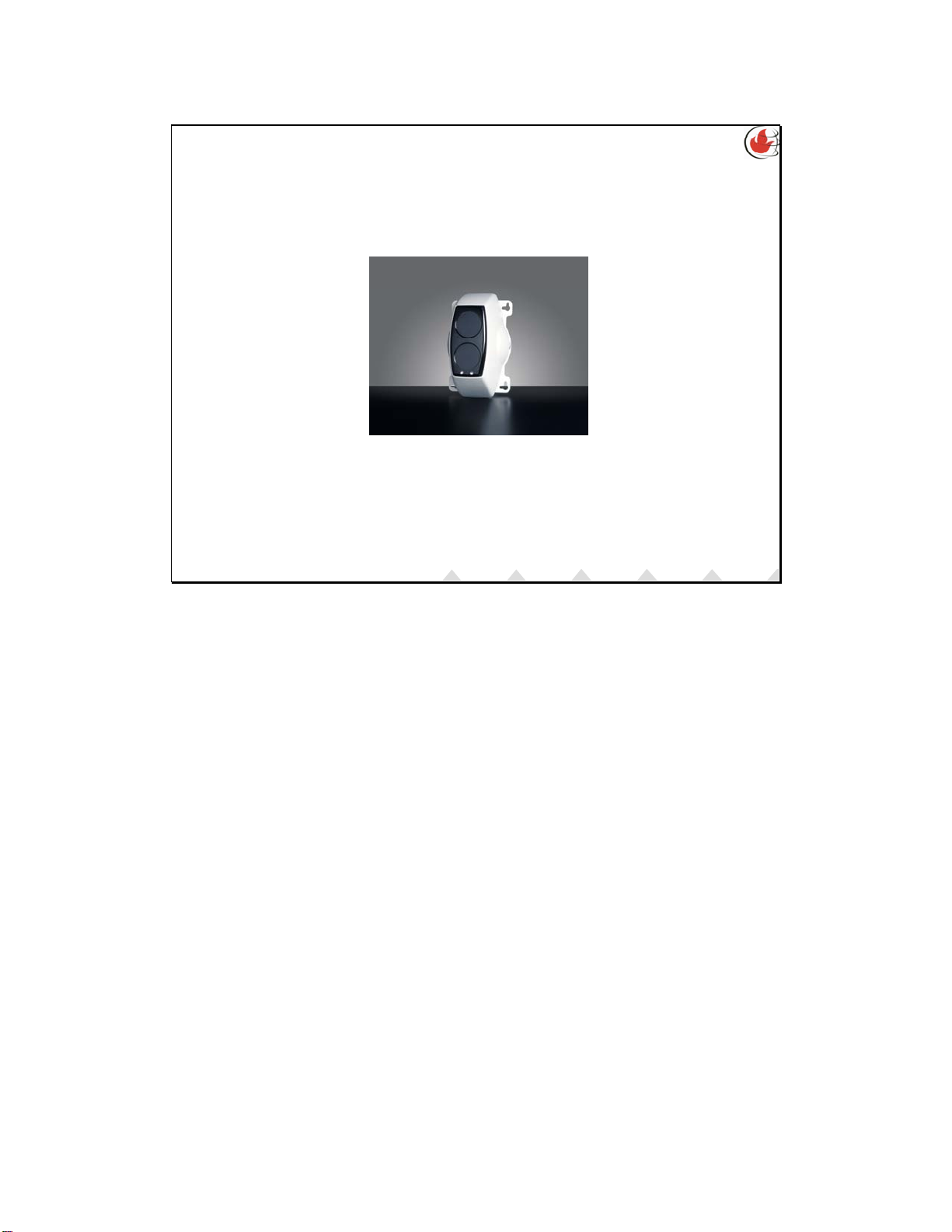
Optical Beam Smoke Detector (Reflective)
TECHMAINTAIN
USECOMMISSIONINSTALLWHAT
Fireray 50/100R is a reflective type beam detector comprising a transmitter and
receiver contained within one enclosure.
It transmits an Infrared beam that is reflected from a retro reflector on the opposite
wall, back to the internal receiver for analysis.
Fireray50/100R reports its status back to the alarm/fire panel or monitoring device.

Copyright © 2008-2010 Fire Fighting Enterprises Ltd.
TECHMAINTAIN
USECOMMISSIONINSTALLWHAT
There are three different types Fireray50/100R:
•Conventional
• Analogue Addressable
• Zone Powered
All of these types are available in either:
• (5 to 50m) or (50 to 100m) versions
VERSIONS OF FIRERAY50/100R
TECHMAINTAIN
USECOMMISSIONINSTALLWHAT
The FIRERAY50/100 comes in two ranges - 5m to 50m and 50m to 100m.
There are a number of variants available in these two ranges.
Conventional:
50RV / 100RV – Standard conventional beam with EN54-12 and CPD approval.
Typically used in Europe.
50RU / 100RU – Standard conventional beam with UL and ULC approval. Typically
used in United States and other countries requiring UL approval.
We also do Analogue Addressable and Zone Powered versions for various
customers.

Copyright © 2008-2010 Fire Fighting Enterprises Ltd.
TECHMAINTAIN
USECOMMISSIONINSTALLWHAT
WHY USE THE FIRERAY50/100R?
• 3 year warranty
• Designed, fully assembled and tested at FFE factory
• International Approvals including EN54:12 and UL
• Minimal reflective prisms versus range
Note: If more flexibility is required consider the FIRERAY5000
TECHMAINTAIN
USECOMMISSIONINSTALLWHAT
Any FIRERAY50/100 returned under warranty is replaced with new product without
question, provided the fault is due to a manufacturing fault. We conduct full tests to
establish and resolve causes of failures, improving product quality.
FFE have full control over product quality and minimising customer lead times.
Fully approved by all the internationally recognised authorities including LPCB, UL,
VdS, VNIIPO (Russia)
Needs only 1 reflective prism for 5 to 50m and only 4 prisms for 50 to 100m.
Adjustable brackets, brackets to hold reflective prisms (surface mount or
adjustable).
Copyright © 2008-2010 Fire Fighting Enterprises Ltd.
TECHMAINTAIN
USECOMMISSIONINSTALLWHAT
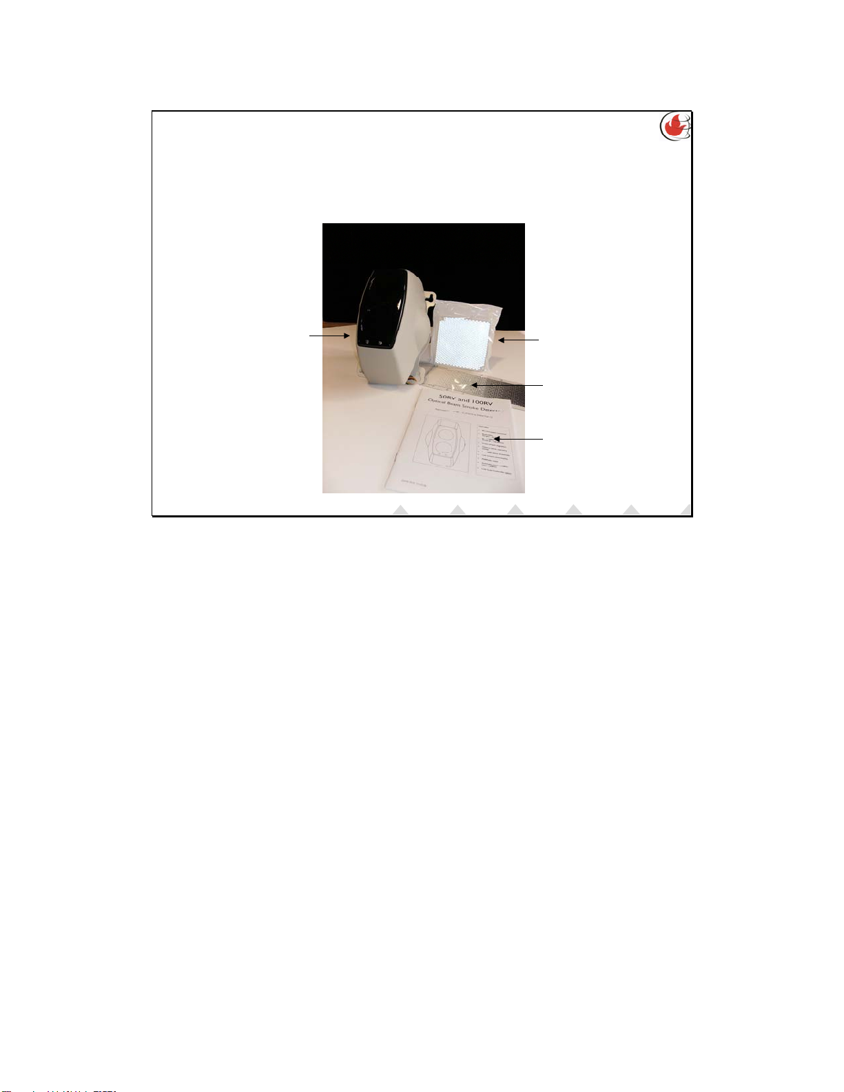
OUT OF THE BOX
BREAKDOWN OF PARTS
Detector
(Fly lead
connected to
detector)
Reflector
Test Filter
User Guide
TECHMAINTAIN
USECOMMISSIONINSTALLWHAT
The FIRERAY50/100 can be broken down into 2 key elements.
The Detector
Transmits and receives the infrared and then communicates the status to the
alarm/fire panel or device monitor.
The Reflector
Reflects the infrared from the transmitter lens along the same path back onto the
receiver lens.
The number of Reflectors required depends on the operating distance.
5 to 50m = 1 Reflector
50 to 100m = 4 Reflectors.
Note the additional 3 reflectors required for 50 to 100m operation must be
purchased separately as the Long Range Kit.
Additional components
In the box one will also find the User Guide, test filter and the fly lead for the
detector. No End-Of-Line components or Fire resistors are provided as these
components are fire panel specific and as such are normally provided by the fire
panel manufacture.

Copyright © 2008-2010 Fire Fighting Enterprises Ltd.
TECHMAINTAIN
USECOMMISSIONINSTALLWHAT
INSTALLATION & WIRING
FOR 50/100RV & RU
•FIRERAY50/100R to the Fire System
•Cables
• Typical Single Zone Wiring
• Multiple Detectors On Single Zone Wiring
• Mounting of the Detector
TECHMAINTAIN
USECOMMISSIONINSTALLWHAT
Copyright © 2008-2010 Fire Fighting Enterprises Ltd.
TECHMAINTAIN
USECOMMISSIONINSTALLWHAT
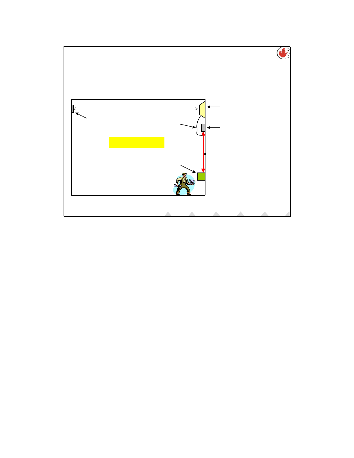
INSTALLING THE FIRERAY50/100R TO
THE FIRE SYSTEM
Detector mounted
at high level
Fire Panel
Dedicated fireproof
screened cable
(1 to 100m)
Protected Area
Reflector Junction Box for fly
lead to fire proof
cable connection
Fly Lead
TECHMAINTAIN
USECOMMISSIONINSTALLWHAT
The Detector and Reflector must to be mounted to a secure structure.
The fly lead that is supplied with the detector should not be extended, but rather
wired into a termination box where it is interfaced to the fire proof cable that goes
back to the fire panel.

Copyright © 2008-2010 Fire Fighting Enterprises Ltd.
TECHMAINTAIN
USECOMMISSIONINSTALLWHAT
CABLES
• It is always advisable to have a dedicated, screened (shielded),
fireproof cable for both power and signal lines
• Don’t leave the shield of the cable unconnected, always connect it
to the earth of the system
• Always mount power and signal cables away from any switching
machinery or HV (High Voltage) lines
• Ensure that any connections are made properly. Intermittent
connections are very difficult to trace and cause problems that
are not easy to diagnose.
TECHMAINTAIN
USECOMMISSIONINSTALLWHAT
Wiring up other equipment with the same cable that is used to monitor or power
the detector can lead to unexpected behavior. It is always best to have a dedicated,
screened cable for the power and the zone wiring. Also avoid the temptation to
place the wiring in the same conduit that may be carrying cables that are used for
large switching machinery or high voltage cables. These can sometimes cause
problems due to mutual induction.
Although it is possible to have a long power cable or zone cable, it is always worth
remembering that that shorter the cable the less the risk of there being any
interference on the cable.

Copyright © 2008-2010 Fire Fighting Enterprises Ltd.
TECHMAINTAIN
USECOMMISSIONINSTALLWHAT
TYPICAL SINGLE ZONE WIRING
TECHMAINTAIN
USECOMMISSIONINSTALLWHAT
The diagram can be found in the installation guide for the FIRERAY50/100.
Zone wiring – sometimes called a ‘Conventional’ system.
Note: External PSU, end-of-line device (EOL device), and fire resistor are not
supplied by Fire Fighting Enterprises. The EOL and fire resistor are specified by the
fire panel manufacturer.
The power supply should be able to supply a minimal current of 20mA (between
10.2 to 30v DC to power 1 FIRERAY50/100).
Power should not be applied until all wiring has been completed.
EOL Device and fire resistor are either supplied or specified by the switch monitor
manufacturer.
A complete fire and fault test of the FIRERAY50/100 should be conducted to ensure
correct wiring to the fire panel.
Copyright © 2008-2010 Fire Fighting Enterprises Ltd.
TECHMAINTAIN
USECOMMISSIONINSTALLWHAT
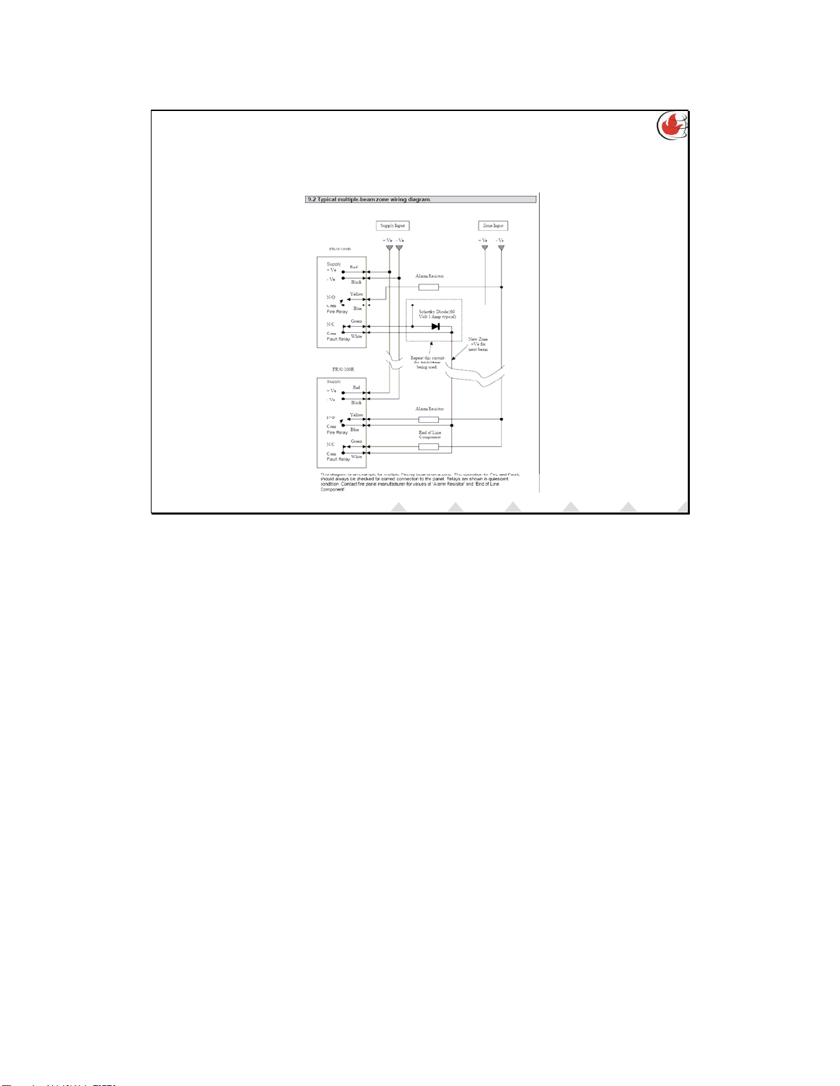
MULTIPLE DETECTORS ON SINGLE ZONE
WIRING
TECHMAINTAIN
USECOMMISSIONINSTALLWHAT
In the event that more than one detector is connected to a “Zone” it is important
to ensure that the fire panel or device monitor is capable of checking for “Detector
out faults”. It is also crucial that the schottky diode is inserted, failing to do so will
not allow a detector further down the zone wiring to report a fire condition if a
detector preceding it goes into a fault condition, as it will break the line to remove
the EOL component from the zone.

Copyright © 2008-2010 Fire Fighting Enterprises Ltd.
TECHMAINTAIN
USECOMMISSIONINSTALLWHAT
MOUNTING OF THE DETECTOR
Do
•Do… Mount onto a secure
structure.
•Do… Fasten all mounting
points before aligning.
•Do… Mount where both
thumb screws and mode switch
are accessible.
•Do… Use the correct number
of reflectors for the required
distance.
Do Not
•Don’t… Mount onto the skin
of a building.
•Don’t… Remove the detector
from the mounting to switch
the mode switch.
•Don’t… Use a single piece of
uni-strut to mount the
detector from the main
structure.
•Don’t… Mount anywhere near
open louvres that could allow
condensation to build up.
•Don’t… Mount where there
will be direct sunlight on the
detector, consider the path of
the sun all year round.
TECHMAINTAIN
USECOMMISSIONINSTALLWHAT
It is not always obvious to installers but one of the crucial elements of a beam type
detector is its mounting!
The detector is designed to compensate for a certain amount of building movement,
it is not designed for poor installation. One of the most useful pieces of kit a
installer can have on his possession is a laser pointer. By mounting this onto the
mounting where the beam is going to go will give you a great deal of information
about the sturdiness of the mounting setup.
If one considers that the beam has a angle of misalignment of 0.8 Degrees then there
is not much required to move the beam off alignment. This is why it is crucial that
the beam in not mounted on plaster board, single pieces of hanging uni-strut… etc...
Copyright © 2008-2010 Fire Fighting Enterprises Ltd.
TECHMAINTAIN
USECOMMISSIONINSTALLWHAT INSTALL
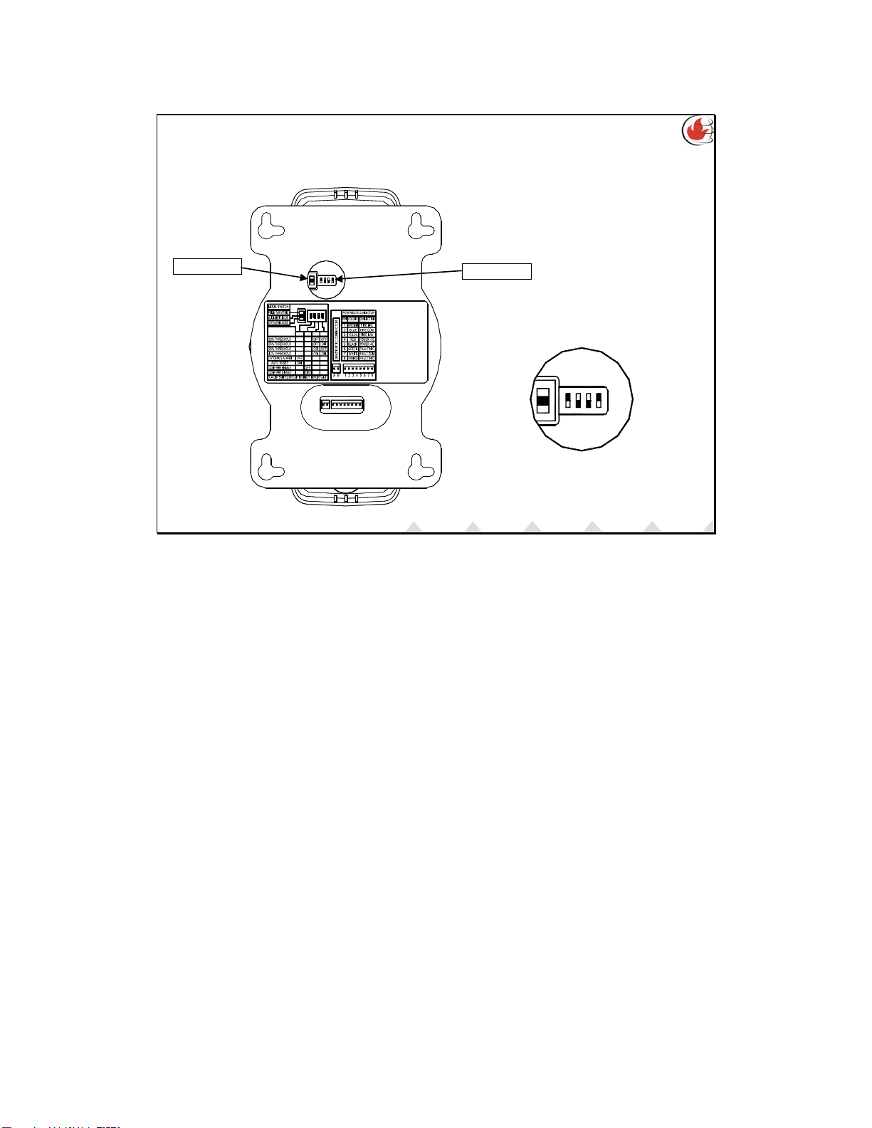
Mode Switch DIP Switches
XXX
X
XX
XX
X
DIP SWITCH
XX
X
X
X
X
X
X
X
2
X
13
X
4
1234
ON
SETTINGS
ON
4321
BEAM SETTINGS PRIOR TO ALIGNMENT
ON
4
321
Shows defaults
Prior to alignment, the user should select the alarm threshold to suit the
environment using the switches shown. See next slide.
Alarm thresholds of 12, 25,35 and 50% can be selected. The Default setting is 35%.
The alarm relay can be set in one of two modes – Auto reset or alarm latching using
switch 1. Auto reset is the factory default setting.
Auto reset mode will reset the alarm relay and alarm LED 5 seconds after received
signal has recovered to a level above the alarm threshold.
Latching mode holds the alarm relay and alarm LED active indefinitely, until cleared
by either:
placing the beam into prism targeting or alignment mode and then going back to run
mode, or
Removing the power to the beam for 10 seconds before powering back up

Copyright © 2008-2010 Fire Fighting Enterprises Ltd.
TECHMAINTAIN
USECOMMISSIONINSTALLWHAT INSTALL
BEAM SETTINGS PRIOR TO ALIGNMENT
Refer to table for DIP switch position for each setting.
Access to the configuration settings is through the back plate of the Detector Head.
Factory default configuration settings are marked .

Copyright © 2008-2010 Fire Fighting Enterprises Ltd.
TECHMAINTAIN
USECOMMISSIONINSTALLWHAT
ALIGNMENT OF BEAM
•BasicCheck
• Three Stages Of Alignment
• Prism Targeting
•AlignmentMode
• Normal Operation
•StatusOfLEDs
•Fault&FireTest
TECHMAINTAIN
USECOMMISSIONINSTALLWHAT

Copyright © 2008-2010 Fire Fighting Enterprises Ltd.
TECHMAINTAIN
USECOMMISSIONINSTALLWHAT
BASIC CHECK
• Isolate the beam from the fire panel
• Make sure the reflector(s) are mounted
• Ensure that the beam path is clear
• Confirm that the beam type and number of reflectors
are correct
TECHMAINTAIN
USECOMMISSIONINSTALLWHAT
While aligning the detector it is advisable to isolate the detector at the fire panel. This will
prevent the alarm from sounding while an installation and/or commissioning are being done.
A reflector is required before alignment can begin. The following should be taken into account
regarding the mounting of the reflector:
Mounted on a secure structure, although it doesn’t need to be as secure as the detectors’
mounting.
Must be within 5 Degrees of perpendicular to the beam path, any greater, then the reflector will
need to be placed on a universal bracket.
Must not be mounted on a reflective surface such as glass, stainless steel or such like. If this is
not avoidable then it is suggested that the reflector is mounted off the perpendicular axis of the
beam. By how much depends on how far the beam is traveling.
Don’t use more reflectors to compensate for poor signal. If the reflectors are used as they
should be with the correct beam (1 for 50m unit, 4 for 100m unit) then there will never be any
need for extra reflectors.
As this type of beam is a reflective type, it does not discriminate where the reflection is coming
from. It is advisable to ensure that there are no objects at least 0.5m from the center of the
beam. Anything within this distance has the possibility to reflect the Infrared back and causing the
installer to align the beam on the reflective surface and not the prism. The larger the path for the
beam the easier and quicker it is to align a detector.
When power is applied to a detector the Red LED will flash. One flash indicates that it is a 50m
unit, two flashes indicate that it is a 100m unit. Make sure that you have the correct unit for the
required distance and that you have the correct number of reflectors as well.

Copyright © 2008-2010 Fire Fighting Enterprises Ltd.
TECHMAINTAIN
USECOMMISSIONINSTALLWHAT
THREE STAGES OF ALIGNMENT
• Prism Targeting Mode
• Used to find the general direction of the prism
•AlignmentMode
• Used to align the beam onto the reflector
• Normal Operation Mode
• Used to save the settings achieved in alignment mode
and put the beam into operation
TECHMAINTAIN
USECOMMISSIONINSTALLWHAT

Copyright © 2008-2010 Fire Fighting Enterprises Ltd.
TECHMAINTAIN
USECOMMISSIONINSTALLWHAT
PRISM TARGETING
• Select this mode by putting the mode switch all the way in
the top position
• The detector then transmits the Infrared beam at is
maximum power setting
• The amber LED flash rate is directly proportional to the
signal strength received
• Using the thumb wheels obtain the fastest flash rate
possible, ‘on constantly’ being desirable
• Confirm that the beam is aligned fully onto the reflector
TECHMAINTAIN
USECOMMISSIONINSTALLWHAT
Prism Targeting Mode
In this mode the detector transmits the Infrared beam at its highest transmit power
level. The amount of signal it receives is directly proportional to the rate at which
the amber LED flashes. You need to get the amber LED to flash at a rate that
seems to make the LED appear as if it is constantly on. To steer the beam you need
to turn the thumb wheels. Move these thumb wheels until you get the constant
amber LED or the fastest flash rate that is possible. Once this has been achieved, go
to the reflector and cover it over with a non reflective material and check that the
amber LED is no longer on or is flashing at a very slow rate (around once a second).
If the reflector and detector are fairly close or the reflector is mounted on a surface
that is slightly reflective then you may get the amber LED flashing at a slow rate. If
you are unable to change the flash rate by covering the reflector then there is a
good chance that you are not on the reflector, uncover the reflector and try again.
Copyright © 2008-2010 Fire Fighting Enterprises Ltd.
TECHMAINTAIN
USECOMMISSIONINSTALLWHAT
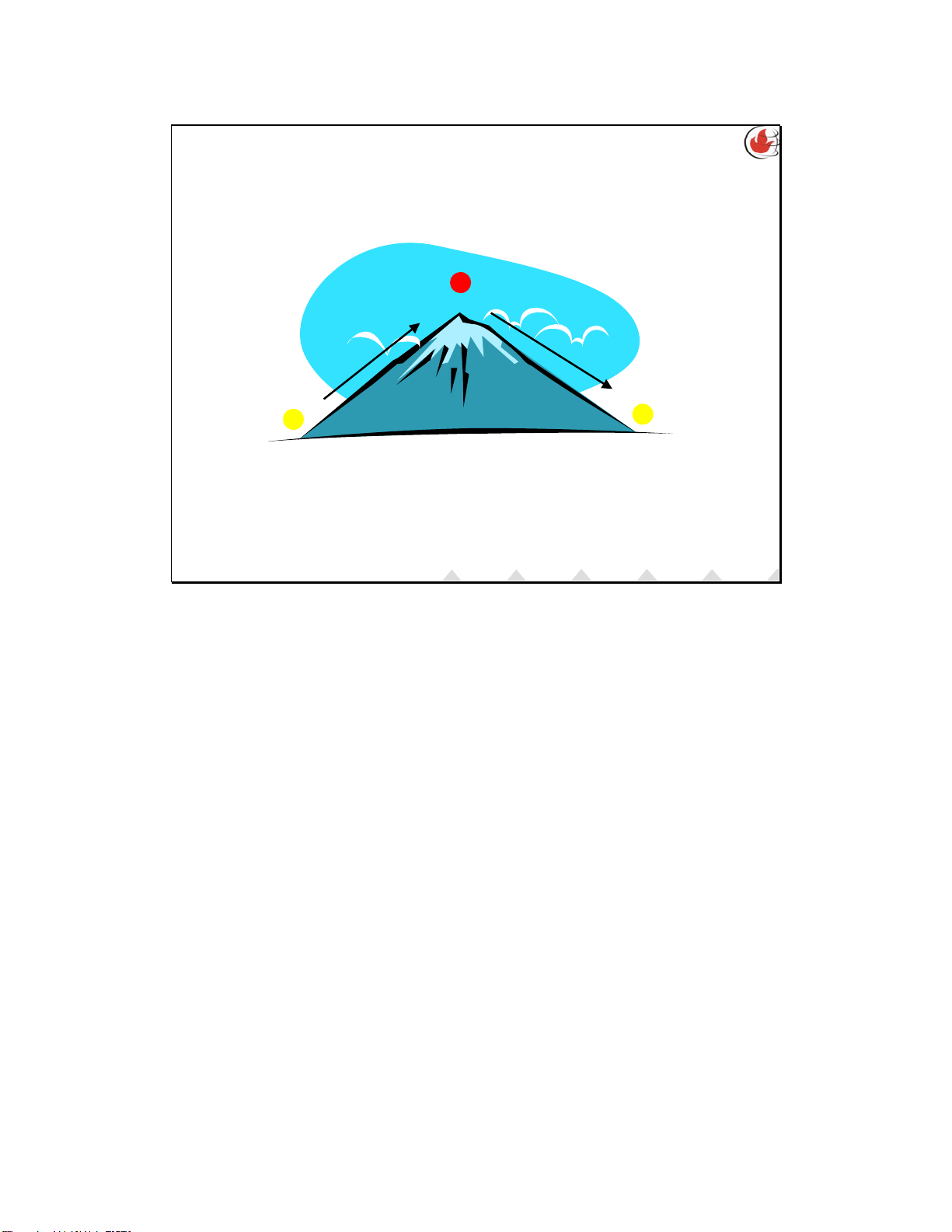
ALIGNMENT MODE
Centre of the Beam on the Reflector = Mountain Peak
TECHMAINTAIN
USECOMMISSIONINSTALLWHAT
If you were to take the analogy that the journey up a mountain was the same as that
to aligning the beam it will make understanding the LEDs much easier.
On the product there are two LEDs. In alignment mode these LEDs indicate the
direction of the transmit power to achieve a 100% received signal strength for the
relative beam position. If the RED LED is flashing it is receiving too much signal as
such the detector is busy reducing it power, if the AMBER LED is flashing then it is
receiving too little signal and as such is busy increasing its power.
If you are never sure which way you should be turning the thumb wheels always
remember that the RED LED is at the top of the mountain and that is where you
need to be. It would be the same as if you where to walk up the side of a mountain
if you are climbing up you would see the RED LED if you overshoot the peak or are
heading in the wrong direction you would see the AMBER LED.
There is the chance that when the installer moves the thumb wheel that they don’t
see any LEDs flashing, this is the case when the amount the beam has moved has not
been enough to change the signal strength, this would be similar to being on the
mountain peak and you are moving straight across, neither up nor down therefore
you would not see any LEDs flashing.
This manual suits for next models
1
Table of contents
Other Fire Fighting Enterprises Smoke Alarm manuals


