Firecom UHW Series User manual

SPECIFICATIONS
W A R R A N T Y
W I R E L E S S H E A D S E T S
Service phone: 503-684-6647
Service em il: [email protected]
Noise Reduction
This Firecom Headset provides 24dB noise attenuation when properly fitted. Any
modification to the Headset will reduce the Headset performance and hearing
damage could occur. Always wear hearing protector in areas that have been
identified as high noise locations.
Federal law requires the following statements:
“Although hearing protectors can be recommended for protection against the
harmful effects of impulsive noise, the Noise Reduction Rating (NRR) is based on
the attenuation of continuous noise and may not be an accurate indicator of the
protection attainable against impulsive noise such as gunfire.”
“The level of noise entering a person’s ear, when a hearing protector is worn as
directed, is closely approximated by the difference between the A-weighted
environmental noise level and the NRR.”
Example
1. The environmental noise level as measured at the ear is 92dBA.
2. The NRR is 24dB.
3. The level of noise entering the ear is approximately equal to 92dBA – NRR or 68dB.
“For noise environments dominated by frequencies below 500 Hz, the
C- weighted environmental noise level should be used.”
FCC/IC Compli nce
This device complies with FCC Part 15 Rules and IC RSS-213 Rules. Operation of
this is subject to the following two conditions:
1. This device may not cause harmful interference.
2. This device must accept any interference that may be received, including
interference that may cause undesired operation.
FCC/IC RF Exposure W rning
• This product complies with FCC radiation exposure limits set forth for an
uncontrolled environment.
• This product may not be collocated or operated in conjunction with any
other antenna or transmitter.
• This headset has been tested and meets the FCC RF exposure guidelines.
Max. SAR is 0.003 W/ kg.
Technic l Spec
Weight (Over the Head) .......................................1.3lb (0.58 Kg)
Weight (Behind the Head).....................................1.2lb (0.53 Kg)
RF
- Range: 1600 feet open field
- Digital encoding for secured communications
- Interference free communications for up to 60 headsets operating in close
proximity
Power
- 3.7V rechargeable lithium polymer battery
- >24 hours battery life when operating @25°C
- Over voltage, under voltage, over current and over temperature protection
- AC Charge source: supplied 12v, 500mA wall charger
- DC Charge source: 5v to16v, 1.5A minimum
- Charge time: 2 hours
Environment l
- IP-65 rated, when worn
- Operating temperature -40°F (-40°C) to +158°F (+70°C)
- Storage temperature -40°F (-40°C) to +185°F (+85°C)
- Charging Temperature 32°F (0°C) to +104°F (+40°C)
MIL SPEC
- Humidity per MIL-STD 810F and 810
- Temperature Shock per MIL-STD 810F and 810
- Chemical Exposure per MIL-STD 810F and 810
SAE
- Salt Spray per J1455, Sec. 4.3
- Vibration per J1455 Sec. 4.9
- Conducted Immunity per J1113-11
- Electrostatic Discharge per J1113-13
- Radiated Emissions per J1113-41
- Radiated Immunity per J1113-21
ISO
- Conducted Transients per 7637-2
C re nd M inten nce
• Inspect ear seals and mic muff frequently for wear. Replace at 6
month intervals. If you see any defect such as holes or cracks in
the ear domes, ear seals, or headband, headset should be
immediately repaired or replaced.
• Do not remove the foam speaker cover.
• To ensure proper function, keep the microphone away from
excessive moisture. Do not store Headset in high temperature
environments or direct sunlight.
• Wipe Headset and ear seals with a mild soap and water mixture
only. The foam mic muff may be removed and cleaned in a mild
detergent, or replaced by ordering from Firecom.
M A I N T E N A N C E
W
ARNING
Never immerse any part of the headset in water.
To Order Firecom Accessories:
Visit www.firecom.com
C ll: 1-800-527-0555
Toggle Up
Power On
Up=PTT On
C
Up=PTT On
C
Turn ON Headset and connect to the
Base Station.
PRO RAMMABLE SQUELCH
A
Turn Headset OFF.
B
While holding the toggle switch UP or
hold PTT button down on the dome
turn ON the Headset.
C
Release toggle switch or PTT button
when the REEN LED lights, watch the
RED LED; it will flash the current squelch
setting (i.e. 5 flashes=squelch setting 5).
D
W
ARNING
Holding the toggle switch during turn ON for longer than
5 seconds will unpair the Headset from the Base.
WIRELESSBASE
POWERINTERCOMP
AIR
LINKS
12345
Maximum 1600 feet
•When approching range limit, headset beeps 1 time every
10 seconds before losing LINK to Base Station
• Beep stops when user returns into range
O U T O F R A N E
Autom tic Sleep
If the Headset does not reconnect to the base station within 5
minutes, it will enter a low power mode. Cycle power ON to the
Headset in order to reconnect the link to the Base Station.
© 2011, A Division of Sonetics Corporation. Specifications subject to change without notice.
7340 SW Durham Road • Portland, OR 97224 USA
1-800-527-0555 • Phone: 503-684-6647 • Fax: 503-620-2943
www.firecom.com • email: [email protected]
600-0176-00 RevD
UHW-Series Under the Helmet • FHW-Series Over the Head
E r se ls nd mic muff remov l
Two-Year Limited Warranty to the Original Purchaser
See addendum for full warranty details.
Up
Center
Down
Power On
Power Off
Up=PTT On
C
To save the setting, cycle power.
To change squelch settings; press toggle
switch UP or hold PTT button down on
the dome and count the number of Red
LED flashes. Press the toggle UP or press
the PTT button to change the setting
to the next range and view the number
of RED LED flashes. Once the squelch
setting reaches level 9, the next position
will return to level 1.
For -57 headsets with toggle switch,
go to step F.
For all other headsets go to step G.
For -57 headsets with toggle switch:
To change squelch settings of the bottom
position; Press the toggle DOWN to
change the setting to the next range and
view the number of REEN LED flashes.
Once the squelch setting reaches level 9,
the next position will return to level 1.
Programmable Squelch
1
30dB
1
25dB
1
20dB
1
1
5dB
1
10dB
1
05dB
1
00dB
95dB
90dB
85dB
80dB
LOW NOISE
ENVIRONMENT
FACTORY
SETTING
HIGHNOISE
ENVIRONMENT
1
30dB
1
25dB
1
20dB
1
1
5dB
1
10dB
1
05dB
1
00dB
95dB
90dB
85dB
80dB
1
2
3
5
6
8
9
4
7
-57 FACTORY SETTING
E
F
Firecom 600-0176-00 RevD:La out 1 8/19/11 3:15 PM Page 2

LED Indicators: Charging Depleted Battery
Battery Level Indicator
Number of RED and REEN
Flashes at Turn ON
No Light
(First 20 Minutes of Charging)
Flashing Red
(While Charging)
Steady Green
(Fully Charged)
20 Minutes
0% 100%
2 Hours
Low Battery (2 hour battery life)
Very Low Battery (15 inutes battery life)
Red LED Flashing Slow 3 Beeps Every 10 inutes
Red LED Flashing Fast 6 Beeps Every inute
BATTERY INDICATORS
-40 -30 -20 -10 0 10
Battery Capacity in Hours
Degrees
Centigrade
Battery Life vs Temperature
30
25
20
15
10
5
0
20 . . . . . 60
-40 -22 -4 14 32 50
Degrees
Fahrenheit 68 . . . . .1 40
75%
>
50-75%
25-50%
25%
<
P A I R I N
WARNING
To avoid unpairing of existing Headsets, previously paired
Headsets must be ON and connected before pairing a
new Headset.
1. The unterminated end of the supplied charging cable assembly
and fuse assembly must be wired to the vehicle per the diagram
above.
2. Observe correct polarity when connecting the charger cable to
12V from the vehicle. Connect the RED wire to +12V and the
BLACK wire to battery chassis ground. This will result in a positive
center terminal of the charger jack as shown in the illustration.
3. Charge Headset completely before use with vehicle power 12V
supply or supplied wall mount charger.
4. For maximum battery shelf life, turn OFF the Headset.
W ll Ad pter Ch rging
Only charge the Headset using the supplied 12VDC regulated wall
adapter. Using unregulated wall adapters will damage the Headset
charging circuit and components and void the warranty.
Vehicle Ch rging
Note: Make fuse no further than 18" from the battery.
Note: Only replace fuse with the same type, 1.5A A U.
1.5A Fuse
Vehicle Battery
BLACK to Chassis Ground
RED to Battery+
CHAR IN & INSTALLATIONS
RED
BLACK
Headset with
Toggle Switch
Headset with
PTT Button
WIRELESS BASE
POWER INTERCOM PAIR
LINKS
1 2 3 4 5
LINKS
1 2 3 4 5
Power On
Toggle Up
Power On
PTT Button
Up=PTT On
C
L
L
With power ON to Base Station, press the “Pair” button until
Yellow LINK(S) LED’s flash.
To pair Headset to Base Station; hold toggle switch UP, then
turn power ON to Headset or hold PTT button down on the
dome while turning power ON to Headset. When BOTH
Red/ reen Headset LED’s are alternating, release toggle switch
or PTT button. Headset will connect to base in 30 seconds.
Up=PTT On
C
When the Headset reen LED remains steadily ON the
headset is successfully paired to the base. If the Headset
reen LED flashes rapidly then repeat the pairing procedure.
A
B
C
Up=PTT On
C
Paired Not Paired
Mic Pl cement
Place mic no more than 1/8"
from lips. Placement of mic is
critical for proper operation.
H E A D S E T F E A T U R E S
W
ARNING
If the microphone is positioned incorrectly, you may
experience a reduction or interruption in the audio and
or deterioration in clarity of intercom and radio
communication.
Charging Port
Power/Volume
control Power/Volume
control Charging Port
Toggle-To-Talk Switch
UP=Radio
Center=Factory pre-set: Low Squelch
DOWN=Factory pre-set: High Squelch
PTT Button
He dset Adjustments
Behind-the-Head Headset
Over-the-Head Headsets
Adjustable
headstrap
Adjustable
headband
Adjustable
Boom
Adjustable
Boom
Power/Volume
control
Firecom 600-0176-00 RevD:La out 1 8/19/11 3:15 PM Page 1

LED Indicators: Charging Depleted Battery
Battery Level Indicator
Number of RED and REEN
Flashes at Turn ON
No Light
(First 20 Minutes of Charging)
Flashing Red
(While Charging)
Steady Green
(Fully Charged)
20 Minutes
0% 100%
2 Hours
Low Battery (2 hour battery life)
Very Low Battery (15 inutes battery life)
Red LED Flashing Slow 3 Beeps Every 10 inutes
Red LED Flashing Fast 6 Beeps Every inute
BATTERY INDICATORS
-40 -30 -20 -10 0 10
Battery Capacity in Hours
Degrees
Centigrade
Battery Life vs Temperature
30
25
20
15
10
5
0
20 . . . . . 60
-40 -22 -4 14 32 50
Degrees
Fahrenheit 68 . . . . .1 40
75%
>
50-75%
25-50%
25%
<
P A I R I N
W
ARNING
To avoid unpairing of existing Headsets, previously paired
Headsets must be ON and connected before pairing a
new Headset.
1. The unterminated end of the supplied charging cable assembly
and fuse assembly must be wired to the vehicle per the diagram
above.
2. Observe correct polarity when connecting the charger cable to
12V from the vehicle. Connect the RED wire to +12V and the
BLACK wire to battery chassis ground. This will result in a positive
center terminal of the charger jack as shown in the illustration.
3. Charge Headset completely before use with vehicle power 12V
supply or supplied wall mount charger.
4. For maximum battery shelf life, turn OFF the Headset.
W ll Ad pter Ch rging
Only charge the Headset using the supplied 12VDC regulated wall
adapter. Using unregulated wall adapters will damage the Headset
charging circuit and components and void the warranty.
Vehicle Ch rging
Note: Make fuse no further than 18" from the battery.
Note: Only replace fuse with the same type, 1.5A A U.
1.5A Fuse
Vehicle Battery
BLACK to Chassis Ground
RED to Battery+
CHAR IN & INSTALLATIONS
RED
BLACK
Headset with
Toggle Switch
Headset with
PTT Button
WIRELESS BASE
POWER INTERCOM PAIR
LINKS
1 2 3 4 5
LINKS
1 2 3 4 5
Power On
Toggle Up
Power On
PTT Button
Up=PTT On
C
L
L
With power ON to Base Station, press the “Pair” button until
Yellow LINK(S) LED’s flash.
To pair Headset to Base Station; hold toggle switch UP, then
turn power ON to Headset or hold PTT button down on the
dome while turning power ON to Headset. When BOTH
Red/ reen Headset LED’s are alternating, release toggle switch
or PTT button. Headset will connect to base in 30 seconds.
Up=PTT On
C
When the Headset reen LED remains steadily ON the
headset is successfully paired to the base. If the Headset
reen LED flashes rapidly then repeat the pairing procedure.
A
B
C
Up=PTT On
C
Paired Not Paired
Mic Pl cement
Place mic no more than 1/8"
from lips. Placement of mic is
critical for proper operation.
H E A D S E T F E A T U R E S
WARNING
If the microphone is positioned incorrectly, you may
experience a reduction or interruption in the audio and
or deterioration in clarity of intercom and radio
communication.
Charging Port
Power/Volume
control Power/Volume
control Charging Port
Toggle-To-Talk Switch
UP=Radio
Center=Factory pre-set: Low Squelch
DOWN=Factory pre-set: High Squelch
PTT Button
He dset Adjustments
Behind-the-Head Headset
Over-the-Head Headsets
Adjustable
headstrap
Adjustable
headband
Adjustable
Boom
Adjustable
Boom
Power/Volume
control
Firecom 600-0176-00 RevD:La out 1 8/19/11 3:15 PM Page 1

LED Indicators: Charging Depleted Battery
Battery Level Indicator
Number of RED and REEN
Flashes at Turn ON
No Light
(First 20 Minutes of Charging)
Flashing Red
(While Charging)
Steady Green
(Fully Charged)
20 Minutes
0% 100%
2 Hours
Low Battery (2 hour battery life)
Very Low Battery (15 inutes battery life)
Red LED Flashing Slow 3 Beeps Every 10 inutes
Red LED Flashing Fast 6 Beeps Every inute
BATTERY INDICATORS
-40 -30 -20 -10 0 10
Battery Capacity in Hours
Degrees
Centigrade
Battery Life vs Temperature
30
25
20
15
10
5
0
20 . . . . . 60
-40 -22 -4 14 32 50
Degrees
Fahrenheit 68 . . . . .1 40
75%
>
50-75%
25-50%
25%
<
P A I R I N
W
ARNING
To avoid unpairing of existing Headsets, previously paired
Headsets must be ON and connected before pairing a
new Headset.
1. The unterminated end of the supplied charging cable assembly
and fuse assembly must be wired to the vehicle per the diagram
above.
2. Observe correct polarity when connecting the charger cable to
12V from the vehicle. Connect the RED wire to +12V and the
BLACK wire to battery chassis ground. This will result in a positive
center terminal of the charger jack as shown in the illustration.
3. Charge Headset completely before use with vehicle power 12V
supply or supplied wall mount charger.
4. For maximum battery shelf life, turn OFF the Headset.
W ll Ad pter Ch rging
Only charge the Headset using the supplied 12VDC regulated wall
adapter. Using unregulated wall adapters will damage the Headset
charging circuit and components and void the warranty.
Vehicle Ch rging
Note: Make fuse no further than 18" from the battery.
Note: Only replace fuse with the same type, 1.5A A U.
1.5A Fuse
Vehicle Battery
BLACK to Chassis Ground
RED to Battery+
CHAR IN & INSTALLATIONS
RED
BLACK
Headset with
Toggle Switch
Headset with
PTT Button
WIRELESS BASE
POWER INTERCOM PAIR
LINKS
1 2 3 4 5
LINKS
1 2 3 4 5
Power On
Toggle Up
Power On
PTT Button
Up=PTT On
C
L
L
With power ON to Base Station, press the “Pair” button until
Yellow LINK(S) LED’s flash.
To pair Headset to Base Station; hold toggle switch UP, then
turn power ON to Headset or hold PTT button down on the
dome while turning power ON to Headset. When BOTH
Red/ reen Headset LED’s are alternating, release toggle switch
or PTT button. Headset will connect to base in 30 seconds.
Up=PTT On
C
When the Headset reen LED remains steadily ON the
headset is successfully paired to the base. If the Headset
reen LED flashes rapidly then repeat the pairing procedure.
A
B
C
Up=PTT On
C
Paired Not Paired
Mic Pl cement
Place mic no more than 1/8"
from lips. Placement of mic is
critical for proper operation.
H E A D S E T F E A T U R E S
WARNING
If the microphone is positioned incorrectly, you may
experience a reduction or interruption in the audio and
or deterioration in clarity of intercom and radio
communication.
Charging Port
Power/Volume
control Power/Volume
control Charging Port
Toggle-To-Talk Switch
UP=Radio
Center=Factory pre-set: Low Squelch
DOWN=Factory pre-set: High Squelch
PTT Button
He dset Adjustments
Behind-the-Head Headset
Over-the-Head Headsets
Adjustable
headstrap
Adjustable
headband
Adjustable
Boom
Adjustable
Boom
Power/Volume
control
Firecom 600-0176-00 RevD:La out 1 8/19/11 3:15 PM Page 1

LED Indicators: Charging Depleted Battery
Battery Level Indicator
Number of RED and REEN
Flashes at Turn ON
No Light
(First 20 Minutes of Charging)
Flashing Red
(While Charging)
Steady Green
(Fully Charged)
20 Minutes
0% 100%
2 Hours
Low Battery (2 hour battery life)
Very Low Battery (15 inutes battery life)
Red LED Flashing Slow 3 Beeps Every 10 inutes
Red LED Flashing Fast 6 Beeps Every inute
BATTERY INDICATORS
-40 -30 -20 -10 0 10
Battery Capacity in Hours
Degrees
Centigrade
Battery Life vs Temperature
30
25
20
15
10
5
0
20 . . . . . 60
-40 -22 -4 14 32 50
Degrees
Fahrenheit 68 . . . . .1 40
75%
>
50-75%
25-50%
25%
<
P A I R I N
W
ARNING
To avoid unpairing of existing Headsets, previously paired
Headsets must be ON and connected before pairing a
new Headset.
1. The unterminated end of the supplied charging cable assembly
and fuse assembly must be wired to the vehicle per the diagram
above.
2. Observe correct polarity when connecting the charger cable to
12V from the vehicle. Connect the RED wire to +12V and the
BLACK wire to battery chassis ground. This will result in a positive
center terminal of the charger jack as shown in the illustration.
3. Charge Headset completely before use with vehicle power 12V
supply or supplied wall mount charger.
4. For maximum battery shelf life, turn OFF the Headset.
W ll Ad pter Ch rging
Only charge the Headset using the supplied 12VDC regulated wall
adapter. Using unregulated wall adapters will damage the Headset
charging circuit and components and void the warranty.
Vehicle Ch rging
Note: Make fuse no further than 18" from the battery.
Note: Only replace fuse with the same type, 1.5A A U.
1.5A Fuse
Vehicle Battery
BLACK to Chassis Ground
RED to Battery+
CHAR IN & INSTALLATIONS
RED
BLACK
Headset with
Toggle Switch
Headset with
PTT Button
WIRELESS BASE
POWER INTERCOM PAIR
LINKS
1 2 3 4 5
LINKS
1 2 3 4 5
Power On
Toggle Up
Power On
PTT Button
Up=PTT On
C
L
L
With power ON to Base Station, press the “Pair” button until
Yellow LINK(S) LED’s flash.
To pair Headset to Base Station; hold toggle switch UP, then
turn power ON to Headset or hold PTT button down on the
dome while turning power ON to Headset. When BOTH
Red/ reen Headset LED’s are alternating, release toggle switch
or PTT button. Headset will connect to base in 30 seconds.
Up=PTT On
C
When the Headset reen LED remains steadily ON the
headset is successfully paired to the base. If the Headset
reen LED flashes rapidly then repeat the pairing procedure.
A
B
C
Up=PTT On
C
Paired Not Paired
Mic Pl cement
Place mic no more than 1/8"
from lips. Placement of mic is
critical for proper operation.
H E A D S E T F E A T U R E S
WARNING
If the microphone is positioned incorrectly, you may
experience a reduction or interruption in the audio and
or deterioration in clarity of intercom and radio
communication.
Charging Port
Power/Volume
control Power/Volume
control Charging Port
Toggle-To-Talk Switch
UP=Radio
Center=Factory pre-set: Low Squelch
DOWN=Factory pre-set: High Squelch
PTT Button
He dset Adjustments
Behind-the-Head Headset
Over-the-Head Headsets
Adjustable
headstrap
Adjustable
headband
Adjustable
Boom
Adjustable
Boom
Power/Volume
control
Firecom 600-0176-00 RevD:La out 1 8/19/11 3:15 PM Page 1

SPECIFICATIONS
W A R R A N T Y
W I R E L E S S H E A D S E T S
Service phone: 503-684-6647
Service em il: service@firecom.com
Noise Reduction
This Firecom Headset provides 24dB noise attenuation when properly fitted. Any
modification to the Headset will reduce the Headset performance and hearing
damage could occur. Always wear hearing protector in areas that have been
identified as high noise locations.
Federal law requires the following statements:
“Although hearing protectors can be recommended for protection against the
harmful effects of impulsive noise, the Noise Reduction Rating (NRR) is based on
the attenuation of continuous noise and may not be an accurate indicator of the
protection attainable against impulsive noise such as gunfire.”
“The level of noise entering a person’s ear, when a hearing protector is worn as
directed, is closely approximated by the difference between the A-weighted
environmental noise level and the NRR.”
Example
1. The environmental noise level as measured at the ear is 92dBA.
2. The NRR is 24dB.
3. The level of noise entering the ear is approximately equal to 92dBA – NRR or 68dB.
“For noise environments dominated by frequencies below 500 Hz, the
C- weighted environmental noise level should be used.”
FCC/IC Compli nce
This device complies with FCC Part 15 Rules and IC RSS-213 Rules. Operation of
this is subject to the following two conditions:
1. This device may not cause harmful interference.
2. This device must accept any interference that may be received, including
interference that may cause undesired operation.
FCC/IC RF Exposure W rning
• This product complies with FCC radiation exposure limits set forth for an
uncontrolled environment.
• This product may not be collocated or operated in conjunction with any
other antenna or transmitter.
• This headset has been tested and meets the FCC RF exposure guidelines.
Max. SAR is 0.003 W/ kg.
Technic l Spec
Weight (Over the Head) .......................................1.3lb (0.58 Kg)
Weight (Behind the Head).....................................1.2lb (0.53 Kg)
RF
- Range: 1600 feet open field
- Digital encoding for secured communications
- Interference free communications for up to 60 headsets operating in close
proximity
Power
- 3.7V rechargeable lithium polymer battery
- >24 hours battery life when operating @25°C
- Over voltage, under voltage, over current and over temperature protection
- AC Charge source: supplied 12v, 500mA wall charger
- DC Charge source: 5v to16v, 1.5A minimum
- Charge time: 2 hours
Environment l
- IP-65 rated, when worn
- Operating temperature -40°F (-40°C) to +158°F (+70°C)
- Storage temperature -40°F (-40°C) to +185°F (+85°C)
- Charging Temperature 32°F (0°C) to +104°F (+40°C)
MIL SPEC
- Humidity per MIL-STD 810F and 810
- Temperature Shock per MIL-STD 810F and 810
- Chemical Exposure per MIL-STD 810F and 810
SAE
- Salt Spray per J1455, Sec. 4.3
- Vibration per J1455 Sec. 4.9
- Conducted Immunity per J1113-11
- Electrostatic Discharge per J1113-13
- Radiated Emissions per J1113-41
- Radiated Immunity per J1113-21
ISO
- Conducted Transients per 7637-2
C re nd M inten nce
• Inspect ear seals and mic muff frequently for wear. Replace at 6
month intervals. If you see any defect such as holes or cracks in
the ear domes, ear seals, or headband, headset should be
immediately repaired or replaced.
• Do not remove the foam speaker cover.
• To ensure proper function, keep the microphone away from
excessive moisture. Do not store Headset in high temperature
environments or direct sunlight.
• Wipe Headset and ear seals with a mild soap and water mixture
only. The foam mic muff may be removed and cleaned in a mild
detergent, or replaced by ordering from Firecom.
M A I N T E N A N C E
WARNING
Never immerse any part of the headset in water.
To Order Firecom Accessories:
Visit www.firecom.com
C ll: 1-800-527-0555
Toggle Up
Power On
Up=PTT On
C
Up=PTT On
C
Turn ON Headset and connect to the
Base Station.
PRO RAMMABLE SQUELCH
A
Turn Headset OFF.
B
While holding the toggle switch UP or
hold PTT button down on the dome
turn ON the Headset.
C
Release toggle switch or PTT button
when the REEN LED lights, watch the
RED LED; it will flash the current squelch
setting (i.e. 5 flashes=squelch setting 5).
D
W
ARNING
Holding the toggle switch during turn ON for longer than
5 seconds will unpair the Headset from the Base.
WIRELESSBASE
POWERINTERCOMP
AIR
LINKS
12345
Maximum 1600 feet
•When approching range limit, headset beeps 1 time every
10 seconds before losing LINK to Base Station
• Beep stops when user returns into range
O U T O F R A N E
Autom tic Sleep
If the Headset does not reconnect to the base station within 5
minutes, it will enter a low power mode. Cycle power ON to the
Headset in order to reconnect the link to the Base Station.
© 2011, A Division of Sonetics Corporation. Specifications subject to change without notice.
7340 SW Durham Road • Portland, OR 97224 USA
1-800-527-0555 • Phone: 503-684-6647 • Fax: 503-620-2943
www.firecom.com • email: sales@firecom.com
600-0176-00 RevD
UHW-Series Under the Helmet • FHW-Series Over the Head
E r se ls nd mic muff remov l
Two-Year Limited Warranty to the Original Purchaser
See addendum for full warranty details.
Up
Center
Down
Power On
Power Off
Up=PTT On
C
To save the setting, cycle power.
To change squelch settings; press toggle
switch UP or hold PTT button down on
the dome and count the number of Red
LED flashes. Press the toggle UP or press
the PTT button to change the setting
to the next range and view the number
of RED LED flashes. Once the squelch
setting reaches level 9, the next position
will return to level 1.
For -57 headsets with toggle switch,
go to step F.
For all other headsets go to step G.
For -57 headsets with toggle switch:
To change squelch settings of the bottom
position; Press the toggle DOWN to
change the setting to the next range and
view the number of REEN LED flashes.
Once the squelch setting reaches level 9,
the next position will return to level 1.
Programmable Squelch
1
30dB
1
25dB
1
20dB
1
1
5dB
1
10dB
1
05dB
1
00dB
95dB
90dB
85dB
80dB
LOW NOISE
ENVIRONMENT
FACTORY
SETTING
HIGHNOISE
ENVIRONMENT
1
30dB
1
25dB
1
20dB
1
1
5dB
1
10dB
1
05dB
1
00dB
95dB
90dB
85dB
80dB
1
2
3
5
6
8
9
4
7
-57FACTORY SETTING
E
F
Firecom 600-0176-00 RevD:La out 1 8/19/11 3:15 PM Page 2

SPECIFICATIONS
W A R R A N T Y
W I R E L E S S H E A D S E T S
Service phone: 503-684-6647
Service em il: service@firecom.com
Noise Reduction
This Firecom Headset provides 24dB noise attenuation when properly fitted. Any
modification to the Headset will reduce the Headset performance and hearing
damage could occur. Always wear hearing protector in areas that have been
identified as high noise locations.
Federal law requires the following statements:
“Although hearing protectors can be recommended for protection against the
harmful effects of impulsive noise, the Noise Reduction Rating (NRR) is based on
the attenuation of continuous noise and may not be an accurate indicator of the
protection attainable against impulsive noise such as gunfire.”
“The level of noise entering a person’s ear, when a hearing protector is worn as
directed, is closely approximated by the difference between the A-weighted
environmental noise level and the NRR.”
Example
1. The environmental noise level as measured at the ear is 92dBA.
2. The NRR is 24dB.
3. The level of noise entering the ear is approximately equal to 92dBA – NRR or 68dB.
“For noise environments dominated by frequencies below 500 Hz, the
C- weighted environmental noise level should be used.”
FCC/IC Compli nce
This device complies with FCC Part 15 Rules and IC RSS-213 Rules. Operation of
this is subject to the following two conditions:
1. This device may not cause harmful interference.
2. This device must accept any interference that may be received, including
interference that may cause undesired operation.
FCC/IC RF Exposure W rning
• This product complies with FCC radiation exposure limits set forth for an
uncontrolled environment.
• This product may not be collocated or operated in conjunction with any
other antenna or transmitter.
• This headset has been tested and meets the FCC RF exposure guidelines.
Max. SAR is 0.003 W/ kg.
Technic l Spec
Weight (Over the Head) .......................................1.3lb (0.58 Kg)
Weight (Behind the Head).....................................1.2lb (0.53 Kg)
RF
- Range: 1600 feet open field
- Digital encoding for secured communications
- Interference free communications for up to 60 headsets operating in close
proximity
Power
- 3.7V rechargeable lithium polymer battery
- >24 hours battery life when operating @25°C
- Over voltage, under voltage, over current and over temperature protection
- AC Charge source: supplied 12v, 500mA wall charger
- DC Charge source: 5v to16v, 1.5A minimum
- Charge time: 2 hours
Environment l
- IP-65 rated, when worn
- Operating temperature -40°F (-40°C) to +158°F (+70°C)
- Storage temperature -40°F (-40°C) to +185°F (+85°C)
- Charging Temperature 32°F (0°C) to +104°F (+40°C)
MIL SPEC
- Humidity per MIL-STD 810F and 810
- Temperature Shock per MIL-STD 810F and 810
- Chemical Exposure per MIL-STD 810F and 810
SAE
- Salt Spray per J1455, Sec. 4.3
- Vibration per J1455 Sec. 4.9
- Conducted Immunity per J1113-11
- Electrostatic Discharge per J1113-13
- Radiated Emissions per J1113-41
- Radiated Immunity per J1113-21
ISO
- Conducted Transients per 7637-2
C re nd M inten nce
• Inspect ear seals and mic muff frequently for wear. Replace at 6
month intervals. If you see any defect such as holes or cracks in
the ear domes, ear seals, or headband, headset should be
immediately repaired or replaced.
• Do not remove the foam speaker cover.
• To ensure proper function, keep the microphone away from
excessive moisture. Do not store Headset in high temperature
environments or direct sunlight.
• Wipe Headset and ear seals with a mild soap and water mixture
only. The foam mic muff may be removed and cleaned in a mild
detergent, or replaced by ordering from Firecom.
M A I N T E N A N C E
WARNING
Never immerse any part of the headset in water.
To Order Firecom Accessories:
Visit www.firecom.com
C ll: 1-800-527-0555
Toggle Up
Power On
Up=PTT On
C
Up=PTT On
C
Turn ON Headset and connect to the
Base Station.
PRO RAMMABLE SQUELCH
A
Turn Headset OFF.
B
While holding the toggle switch UP or
hold PTT button down on the dome
turn ON the Headset.
C
Release toggle switch or PTT button
when the REEN LED lights, watch the
RED LED; it will flash the current squelch
setting (i.e. 5 flashes=squelch setting 5).
D
W
ARNING
Holding the toggle switch during turn ON for longer than
5 seconds will unpair the Headset from the Base.
WIRELESSBASE
POWERINTERCOMP
AIR
LINKS
12345
Maximum 1600 feet
•When approching range limit, headset beeps 1 time every
10 seconds before losing LINK to Base Station
• Beep stops when user returns into range
O U T O F R A N E
Autom tic Sleep
If the Headset does not reconnect to the base station within 5
minutes, it will enter a low power mode. Cycle power ON to the
Headset in order to reconnect the link to the Base Station.
© 2011, A Division of Sonetics Corporation. Specifications subject to change without notice.
7340 SW Durham Road • Portland, OR 97224 USA
1-800-527-0555 • Phone: 503-684-6647 • Fax: 503-620-2943
www.firecom.com • email: sales@firecom.com
600-0176-00 RevD
UHW-Series Under the Helmet • FHW-Series Over the Head
E r se ls nd mic muff remov l
Two-Year Limited Warranty to the Original Purchaser
See addendum for full warranty details.
Up
Center
Down
Power On
Power Off
Up=PTT On
C
To save the setting, cycle power.
To change squelch settings; press toggle
switch UP or hold PTT button down on
the dome and count the number of Red
LED flashes. Press the toggle UP or press
the PTT button to change the setting
to the next range and view the number
of RED LED flashes. Once the squelch
setting reaches level 9, the next position
will return to level 1.
For -57 headsets with toggle switch,
go to step F.
For all other headsets go to step G.
For -57 headsets with toggle switch:
To change squelch settings of the bottom
position; Press the toggle DOWN to
change the setting to the next range and
view the number of REEN LED flashes.
Once the squelch setting reaches level 9,
the next position will return to level 1.
Programmable Squelch
1
30dB
1
25dB
1
20dB
1
1
5dB
1
10dB
1
05dB
1
00dB
95dB
90dB
85dB
80dB
LOW NOISE
ENVIRONMENT
F
ACTORY
SETTING
HIGHNOISE
ENVIRONMENT
1
30dB
1
25dB
1
20dB
1
1
5dB
1
10dB
1
05dB
1
00dB
95dB
90dB
85dB
80dB
1
2
3
5
6
8
9
4
7
-57 FACTOR
Y SETTING
E
F
Firecom 600-0176-00 RevD:La out 1 8/19/11 3:15 PM Page 2

SPECIFICATIONS
W A R R A N T Y
W I R E L E S S H E A D S E T S
Service phone: 503-684-6647
Service em il: service@firecom.com
Noise Reduction
This Firecom Headset provides 24dB noise attenuation when properly fitted. Any
modification to the Headset will reduce the Headset performance and hearing
damage could occur. Always wear hearing protector in areas that have been
identified as high noise locations.
Federal law requires the following statements:
“Although hearing protectors can be recommended for protection against the
harmful effects of impulsive noise, the Noise Reduction Rating (NRR) is based on
the attenuation of continuous noise and may not be an accurate indicator of the
protection attainable against impulsive noise such as gunfire.”
“The level of noise entering a person’s ear, when a hearing protector is worn as
directed, is closely approximated by the difference between the A-weighted
environmental noise level and the NRR.”
Example
1. The environmental noise level as measured at the ear is 92dBA.
2. The NRR is 24dB.
3. The level of noise entering the ear is approximately equal to 92dBA – NRR or 68dB.
“For noise environments dominated by frequencies below 500 Hz, the
C- weighted environmental noise level should be used.”
FCC/IC Compli nce
This device complies with FCC Part 15 Rules and IC RSS-213 Rules. Operation of
this is subject to the following two conditions:
1. This device may not cause harmful interference.
2. This device must accept any interference that may be received, including
interference that may cause undesired operation.
FCC/IC RF Exposure W rning
• This product complies with FCC radiation exposure limits set forth for an
uncontrolled environment.
• This product may not be collocated or operated in conjunction with any
other antenna or transmitter.
• This headset has been tested and meets the FCC RF exposure guidelines.
Max. SAR is 0.003 W/ kg.
Technic l Spec
Weight (Over the Head) .......................................1.3lb (0.58 Kg)
Weight (Behind the Head).....................................1.2lb (0.53 Kg)
RF
- Range: 1600 feet open field
- Digital encoding for secured communications
- Interference free communications for up to 60 headsets operating in close
proximity
Power
- 3.7V rechargeable lithium polymer battery
- >24 hours battery life when operating @25°C
- Over voltage, under voltage, over current and over temperature protection
- AC Charge source: supplied 12v, 500mA wall charger
- DC Charge source: 5v to16v, 1.5A minimum
- Charge time: 2 hours
Environment l
- IP-65 rated, when worn
- Operating temperature -40°F (-40°C) to +158°F (+70°C)
- Storage temperature -40°F (-40°C) to +185°F (+85°C)
- Charging Temperature 32°F (0°C) to +104°F (+40°C)
MIL SPEC
- Humidity per MIL-STD 810F and 810
- Temperature Shock per MIL-STD 810F and 810
- Chemical Exposure per MIL-STD 810F and 810
SAE
- Salt Spray per J1455, Sec. 4.3
- Vibration per J1455 Sec. 4.9
- Conducted Immunity per J1113-11
- Electrostatic Discharge per J1113-13
- Radiated Emissions per J1113-41
- Radiated Immunity per J1113-21
ISO
- Conducted Transients per 7637-2
C re nd M inten nce
• Inspect ear seals and mic muff frequently for wear. Replace at 6
month intervals. If you see any defect such as holes or cracks in
the ear domes, ear seals, or headband, headset should be
immediately repaired or replaced.
• Do not remove the foam speaker cover.
• To ensure proper function, keep the microphone away from
excessive moisture. Do not store Headset in high temperature
environments or direct sunlight.
• Wipe Headset and ear seals with a mild soap and water mixture
only. The foam mic muff may be removed and cleaned in a mild
detergent, or replaced by ordering from Firecom.
M A I N T E N A N C E
W
ARNING
Never immerse any part of the headset in water.
To Order Firecom Accessories:
Visit www.firecom.com
C ll: 1-800-527-0555
Toggle Up
Power On
Up=PTT On
C
Up=PTT On
C
Turn ON Headset and connect to the
Base Station.
PRO RAMMABLE SQUELCH
A
Turn Headset OFF.
B
While holding the toggle switch UP or
hold PTT button down on the dome
turn ON the Headset.
C
Release toggle switch or PTT button
when the REEN LED lights, watch the
RED LED; it will flash the current squelch
setting (i.e. 5 flashes=squelch setting 5).
D
W
ARNING
Holding the toggle switch during turn ON for longer than
5 seconds will unpair the Headset from the Base.
WIRELESSBASE
POWERINTERCOMP
AIR
LINKS
12345
Maximum 1600 feet
•When approching range limit, headset beeps 1 time every
10 seconds before losing LINK to Base Station
• Beep stops when user returns into range
O U T O F R A N E
Autom tic Sleep
If the Headset does not reconnect to the base station within 5
minutes, it will enter a low power mode. Cycle power ON to the
Headset in order to reconnect the link to the Base Station.
© 2011, A Division of Sonetics Corporation. Specifications subject to change without notice.
7340 SW Durham Road • Portland, OR 97224 USA
1-800-527-0555 • Phone: 503-684-6647 • Fax: 503-620-2943
www.firecom.com • email: sales@firecom.com
600-0176-00 RevD
UHW-Series Under the Helmet • FHW-Series Over the Head
E r se ls nd mic muff remov l
Two-Year Limited Warranty to the Original Purchaser
See addendum for full warranty details.
Up
Center
Down
Power On
Power Off
Up=PTT On
C
To save the setting, cycle power.
To change squelch settings; press toggle
switch UP or hold PTT button down on
the dome and count the number of Red
LED flashes. Press the toggle UP or press
the PTT button to change the setting
to the next range and view the number
of RED LED flashes. Once the squelch
setting reaches level 9, the next position
will return to level 1.
For -57 headsets with toggle switch,
go to step F.
For all other headsets go to step G.
For -57 headsets with toggle switch:
To change squelch settings of the bottom
position; Press the toggle DOWN to
change the setting to the next range and
view the number of REEN LED flashes.
Once the squelch setting reaches level 9,
the next position will return to level 1.
Programmable Squelch
1
30dB
1
25dB
1
20dB
1
1
5dB
1
10dB
1
05dB
1
00dB
95dB
90dB
85dB
80dB
LOW NOISE
ENVIRONMENT
F
ACTORY
SETTING
HIGH NOISE
ENVIRONMENT
1
30dB
1
25dB
1
20dB
1
1
5dB
1
10dB
1
05dB
1
00dB
95dB
90dB
85dB
80dB
1
2
3
5
6
8
9
4
7
-57F
ACTORY SETTING
E
F
Firecom 600-0176-00 RevD:La out 1 8/19/11 3:15 PM Page 2

SPECIFICATIONS
W A R R A N T Y
W I R E L E S S H E A D S E T S
Service phone: 503-684-6647
Service em il: [email protected]
Noise Reduction
This Firecom Headset provides 24dB noise attenuation when properly fitted. Any
modification to the Headset will reduce the Headset performance and hearing
damage could occur. Always wear hearing protector in areas that have been
identified as high noise locations.
Federal law requires the following statements:
“Although hearing protectors can be recommended for protection against the
harmful effects of impulsive noise, the Noise Reduction Rating (NRR) is based on
the attenuation of continuous noise and may not be an accurate indicator of the
protection attainable against impulsive noise such as gunfire.”
“The level of noise entering a person’s ear, when a hearing protector is worn as
directed, is closely approximated by the difference between the A-weighted
environmental noise level and the NRR.”
Example
1. The environmental noise level as measured at the ear is 92dBA.
2. The NRR is 24dB.
3. The level of noise entering the ear is approximately equal to 92dBA – NRR or 68dB.
“For noise environments dominated by frequencies below 500 Hz, the
C- weighted environmental noise level should be used.”
FCC/IC Compli nce
This device complies with FCC Part 15 Rules and IC RSS-213 Rules. Operation of
this is subject to the following two conditions:
1. This device may not cause harmful interference.
2. This device must accept any interference that may be received, including
interference that may cause undesired operation.
FCC/IC RF Exposure W rning
• This product complies with FCC radiation exposure limits set forth for an
uncontrolled environment.
• This product may not be collocated or operated in conjunction with any
other antenna or transmitter.
• This headset has been tested and meets the FCC RF exposure guidelines.
Max. SAR is 0.003 W/ kg.
Technic l Spec
Weight (Over the Head) .......................................1.3lb (0.58 Kg)
Weight (Behind the Head).....................................1.2lb (0.53 Kg)
RF
- Range: 1600 feet open field
- Digital encoding for secured communications
- Interference free communications for up to 60 headsets operating in close
proximity
Power
- 3.7V rechargeable lithium polymer battery
- >24 hours battery life when operating @25°C
- Over voltage, under voltage, over current and over temperature protection
- AC Charge source: supplied 12v, 500mA wall charger
- DC Charge source: 5v to16v, 1.5A minimum
- Charge time: 2 hours
Environment l
- IP-65 rated, when worn
- Operating temperature -40°F (-40°C) to +158°F (+70°C)
- Storage temperature -40°F (-40°C) to +185°F (+85°C)
- Charging Temperature 32°F (0°C) to +104°F (+40°C)
MIL SPEC
- Humidity per MIL-STD 810F and 810
- Temperature Shock per MIL-STD 810F and 810
- Chemical Exposure per MIL-STD 810F and 810
SAE
- Salt Spray per J1455, Sec. 4.3
- Vibration per J1455 Sec. 4.9
- Conducted Immunity per J1113-11
- Electrostatic Discharge per J1113-13
- Radiated Emissions per J1113-41
- Radiated Immunity per J1113-21
ISO
- Conducted Transients per 7637-2
C re nd M inten nce
• Inspect ear seals and mic muff frequently for wear. Replace at 6
month intervals. If you see any defect such as holes or cracks in
the ear domes, ear seals, or headband, headset should be
immediately repaired or replaced.
• Do not remove the foam speaker cover.
• To ensure proper function, keep the microphone away from
excessive moisture. Do not store Headset in high temperature
environments or direct sunlight.
• Wipe Headset and ear seals with a mild soap and water mixture
only. The foam mic muff may be removed and cleaned in a mild
detergent, or replaced by ordering from Firecom.
M A I N T E N A N C E
W
ARNING
Never immerse any part of the headset in water.
To Order Firecom Accessories:
Visit www.firecom.com
C ll: 1-800-527-0555
Toggle Up
Power On
Up=PTT On
C
Up=PTT On
C
Turn ON Headset and connect to the
Base Station.
PRO RAMMABLE SQUELCH
A
Turn Headset OFF.
B
While holding the toggle switch UP or
hold PTT button down on the dome
turn ON the Headset.
C
Release toggle switch or PTT button
when the REEN LED lights, watch the
RED LED; it will flash the current squelch
setting (i.e. 5 flashes=squelch setting 5).
D
W
ARNING
Holding the toggle switch during turn ON for longer than
5 seconds will unpair the Headset from the Base.
WIRELESSBASE
POWERINTERCOMP
AIR
LINKS
12345
Maximum 1600 feet
•When approching range limit, headset beeps 1 time every
10 seconds before losing LINK to Base Station
• Beep stops when user returns into range
O U T O F R A N E
Autom tic Sleep
If the Headset does not reconnect to the base station within 5
minutes, it will enter a low power mode. Cycle power ON to the
Headset in order to reconnect the link to the Base Station.
© 2011, A Division of Sonetics Corporation. Specifications subject to change without notice.
7340 SW Durham Road • Portland, OR 97224 USA
1-800-527-0555 • Phone: 503-684-6647 • Fax: 503-620-2943
www.firecom.com • email: sales@firecom.com
600-0176-00 RevD
UHW-Series Under the Helmet • FHW-Series Over the Head
E r se ls nd mic muff remov l
Two-Year Limited Warranty to the Original Purchaser
See addendum for full warranty details.
Up
Center
Down
Power On
Power Off
Up=PTT On
C
To save the setting, cycle power.
To change squelch settings; press toggle
switch UP or hold PTT button down on
the dome and count the number of Red
LED flashes. Press the toggle UP or press
the PTT button to change the setting
to the next range and view the number
of RED LED flashes. Once the squelch
setting reaches level 9, the next position
will return to level 1.
For -57 headsets with toggle switch,
go to step F.
For all other headsets go to step G.
For -57 headsets with toggle switch:
To change squelch settings of the bottom
position; Press the toggle DOWN to
change the setting to the next range and
view the number of REEN LED flashes.
Once the squelch setting reaches level 9,
the next position will return to level 1.
Programmable Squelch
1
30dB
1
25dB
1
20dB
1
1
5dB
1
10dB
1
05dB
1
00dB
95dB
90dB
85dB
80dB
LOW NOISE
ENVIRONMENT
FACTORY
SETTING
HIGHNOISE
ENVIRONMENT
1
30dB
1
25dB
1
20dB
1
1
5dB
1
10dB
1
05dB
1
00dB
95dB
90dB
85dB
80dB
1
2
3
5
6
8
9
4
7
-57 FACTORY SETTING
E
F
Firecom 600-0176-00 RevD:La out 1 8/19/11 3:15 PM Page 2
Table of contents
Other Firecom Headset manuals
Firecom
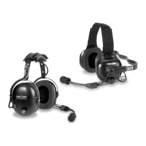
Firecom UHW-Series User manual
Firecom
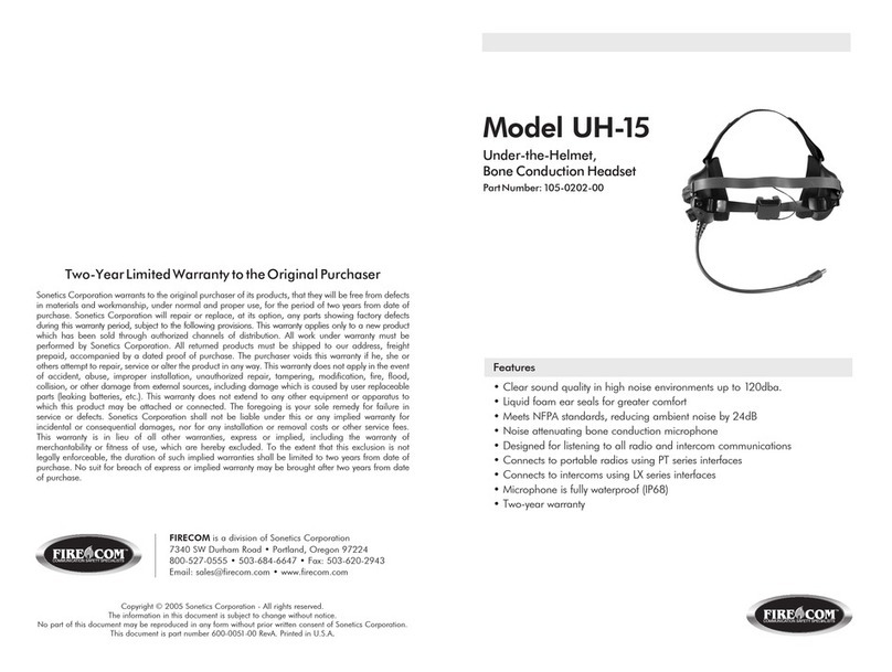
Firecom UH-15 User manual
Firecom
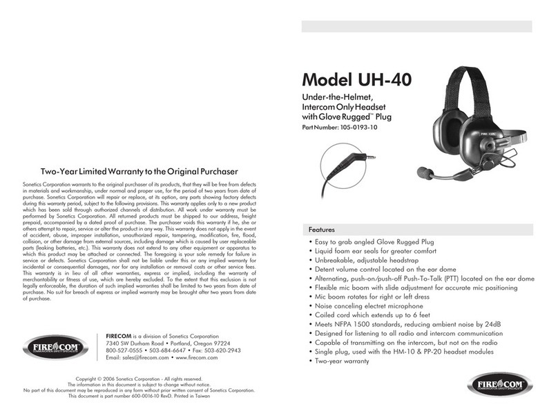
Firecom UH-40 User manual
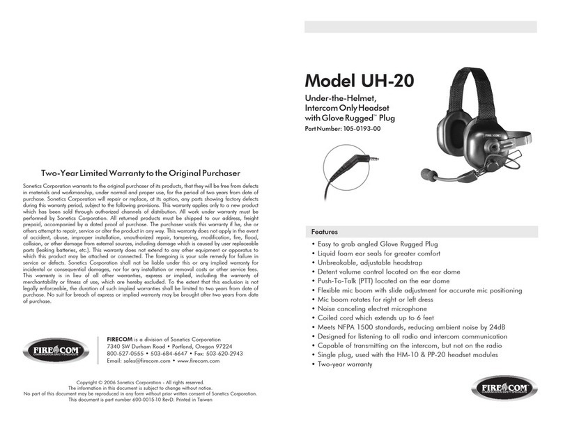
Firecom
Firecom UH-20 User manual
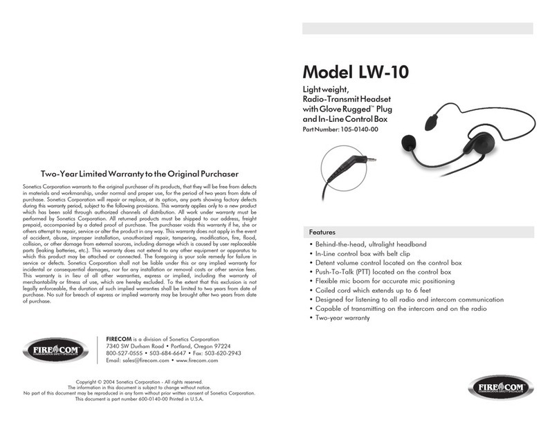
Firecom
Firecom LW-10 User manual
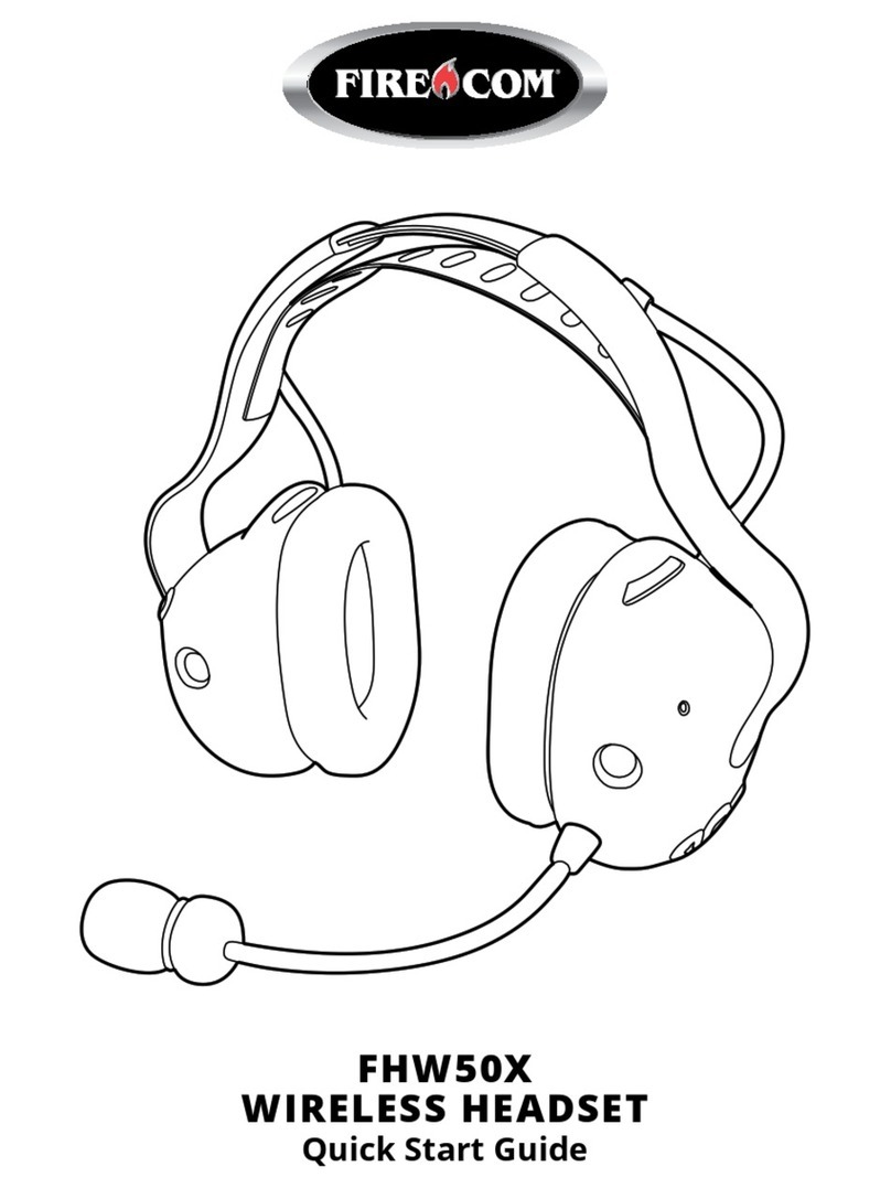
Firecom
Firecom FHW50X User manual
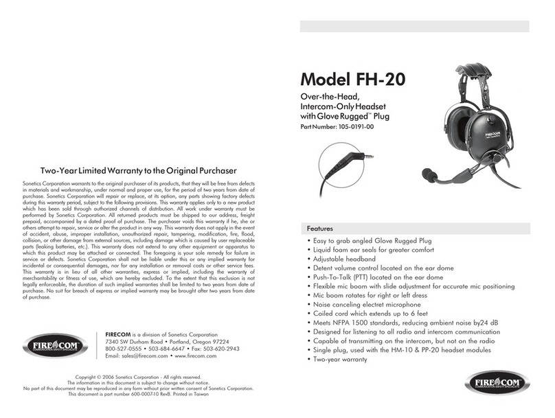
Firecom
Firecom FH-20 User manual
Firecom
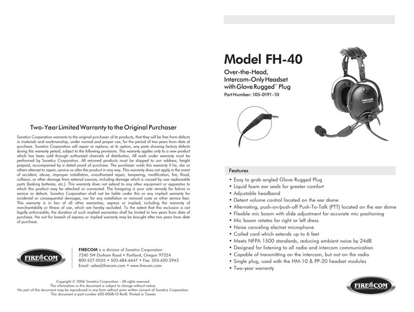
Firecom FH-40 User manual
Firecom
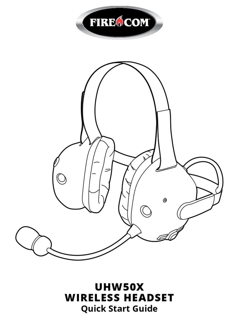
Firecom UHW50X User manual
Firecom
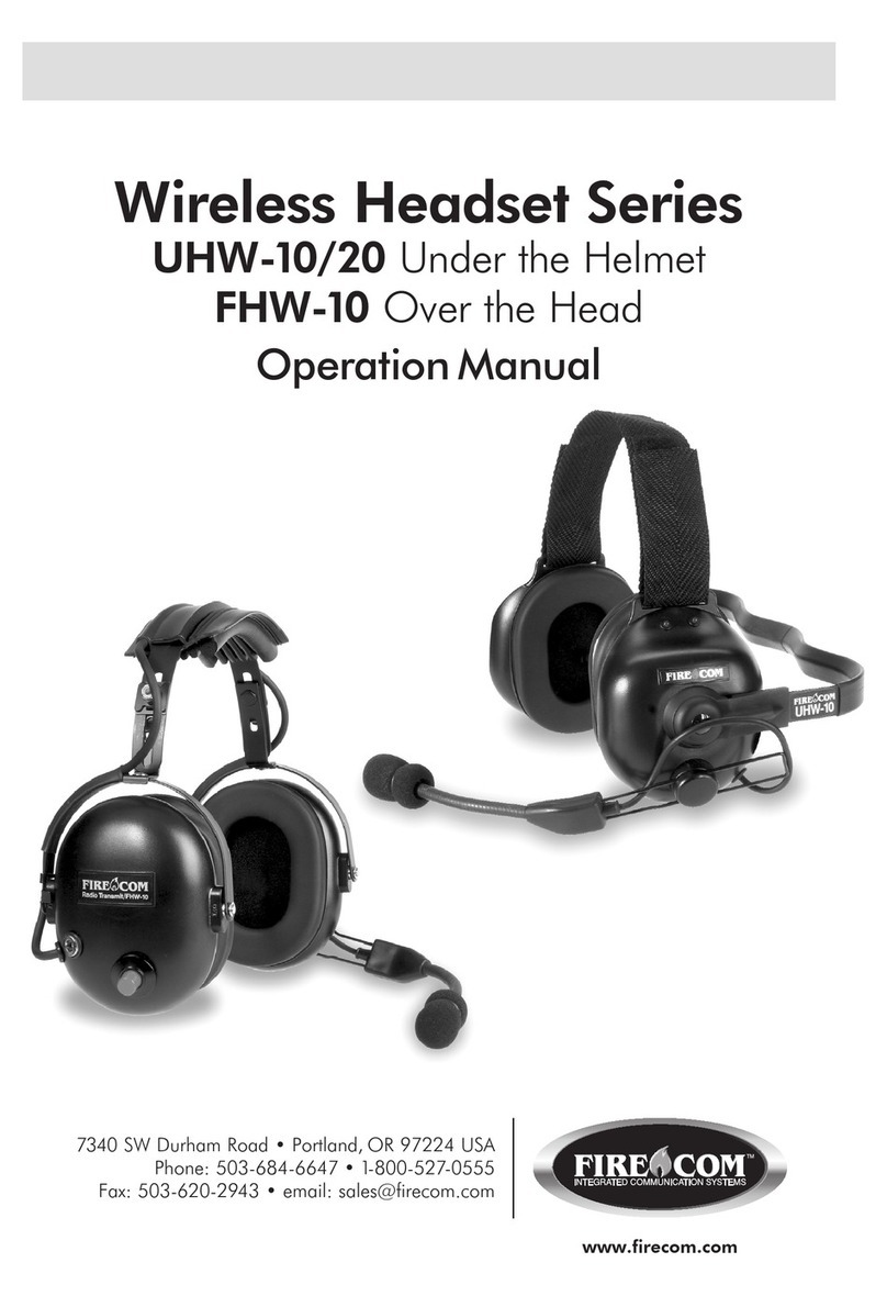
Firecom UHW-10 User manual
