Firecraft Superior Standard BBV-42RMN User manual

1
NOTE: DIAGRAMS & ILLUSTRATIONS NOT TO SCALE.
HOMEOWNER'S CARE AND
OPERATION INSTRUCTIONS
42" B-VENTED GAS APPLIANCES
P/N 725,007M REV. N/C 08/2000
Millivolt Models Electronic Models
BBV-42RMN BBV-42REN
BBV-42RMP BBV-42REP
MODELS
RETAIN THESE INSTRUCTIONS
FOR FUTURE REFERENCE
WH Report No. J99025850
FOR YOUR SAFETY: Do not store or use gasoline
or other flammable vapors or liquids in the vicin-
ity of this or any other appliance.
FOR YOUR SAFETY: What to do if you smell gas:
• DO NOT light any appliance.
• DO NOT touch any electrical switches.
• DO NOT use any phone in your building.
• Immediately call your gas supplier from a
neighbor’s phone.
Follow your gas suppliers instructions.
• Ifyourgassuppliercannotbereached,callthe
fire department.
Installation and service must be performed by a
qualified installer, service agency or the gas
supplier.
WARNING:IFTHEINFORMATIONINTHISMANUAL
IS NOT FOLLOWED EXACTLY, A FIRE OR EXPLO-
SION MAY RESULT CAUSING PROPERTY DAM-
AGE, PERSONAL INJURY OR LOSS OF LIFE.
POURVOTRESÉCURITÉ: Nepasentreposerniutiliser
d'essencenid'autrevapeursouliquidesinflammables
dans le voisinage de cet appareil ou de tout autre
appareil.
POUR VOTRE SÉCURITÉ: Que faire si vous sentez une
odiur de gaz:
• Ne pas tenter d'allumer d'appareil.
• Netouchezàaucuninterrupteur. Nepasvousservir
des téléphones se trouvant dans le batiment où
vous vous trouvez.
• Evacuez la piéce, le bâtiment ou la zone.
• Appelez immédiatement votre fournisseur de gaz
depuis un voisin. Suivez les instructions du
fournisseur.
• Si vous ne pouvez rejoindre le fournisseur de gaz,
appelez le service dos incendies.
L'installation et service doit être exécuté par un
qualifiéinstalleur,agencedeserviceoulefournisseur
de gaz.
AVERTISSEMENT: ASSUREZ-VOUS DE BIEN SUIVRE
LESINSTRUCTIONSDONNÉDANSCETTENOTICEPOUR
RÉDUIRE AU MINIMUM LE RISQUE D'INCENDIE OU
POUR ÉVITER TOUT DOMMAGE MATÉRIEL, TOUTE
BLESSURE OU LA MORT.
STANDARD SERIES
2NOTE: DIAGRAMS & ILLUSTRATIONS NOT TO SCALE.
TABLE OF CONTENTS
Introduction..................................... page 2
General Information......................... page 2
Operation/Care of Your Appliance.... page 3
Damper & Outside Air Controls ....... page 5
Maintenance .................................... page 6
Millivolt Appliance Checkout............ page 6
Electronic Appliance Checkout......... page 6
Maintenance Schedule..................... page 7
Log and Rockwool Placement ......... page 8
Wiring Diagrams.............................. page 9
Lighting Instructions – Millivolt....... page 10
Lighting Instructions – Electronic.... page 12
Troubleshooting Guide – Millivolt ..... page 14
Troubleshooting Guide – Electronic .. page 15
Warranty.......................................... page 16
Product Reference Information ....... page 16
Replacement Parts .......................... page 16
Accessory Components................... page 17
Replacement Parts List..................... page 18
WARNING: IMPROPER INSTALLATION,
ADJUSTMENT, ALTERATION, SERVICE
OR MAINTENANCE CAN CAUSE INJURY
ORPROPERTYDAMAGE. REFERTOTHIS
MANUAL. FOR ASSISTANCE OR ADDI-
TIONAL INFORMATION CONSULT A
QUALIFIED INSTALLER, SERVICE
AGENCY OR THE GAS SUPPLIER.
These appliances are designed to operate on
natural or propane gas only. The use of other
fuels or combination of fuels will degrade the
performance of this system and may be dan-
gerous.
Input of appliance is 30,000 BTU/HR.
WARNING: THESE FIREPLACES ARE
VENTEDDECORATIVEGASAPPLIANCES.
DO NOT BURN WOOD OR OTHER MATE-
RIAL IN THESE APPLIANCES.
CONGRATULATIONS!
InselectingthisSUPERIORB-ventedgasapplianceyouhavechosenthefinestandmost
dependable fireplace to be found anywhere. A beautiful, prestigious, alternative to a
woodburningfireplace. WelcometoaFamilyoftensofthousandsofsatisfiedSUPERIOR
Fireplace Owners.
Please read and carefully follow all of the instructions found in this manual. Please pay
special attention to the safety instructions provided in this manual. The Homeowner's
Care and Operation Instructions included here will assure that you have many years of
dependable and enjoyable service from your SUPERIOR product.
INTRODUCTION
The millivolt appliances are designed to oper-
ateoneithernaturalorpropanegas.Amillivolt
gas control valve with piezo ignition system
provides safe, efficient operation.
The electronic appliances are designed to op-
erate on either natural or propane gas. An
electronic direct spark ignition system pro-
videssafe,efficientoperation.Externalelectri-
cal power is required to operate these units.
TheseappliancescomplywithNationalSafety
Standardsandaretestedandlistedby(Report
No. J99025850) to ANSI Z21.50b - 1998 (in
Canada, CAN/CGA-2.22b-M98 as vented gas
fireplaces.
Installation must conform to local codes. In
the absence of local codes, installation must
comply with the current National Fuel Gas
Code,ANSIZ223.1(NFPA54).(InCanada,the
currentCAN/CGAB149installationcode.) Elec-
tricalwiringmust complywithlocalcodes. In
the absence of local codes, installation must
be in accordance with the National Electrical
Code, NFPA 70 - (latest edition). (In Canada,
thecurrentCSAC22.1CanadianElectricCode.)
DO NOT ATTEMPT TO ALTER OR MODIFY
THE CONSTRUCTION OF THE APPLIANCE OR
ITS COMPONENTS. ANY MODIFICATION OR
ALTERATION MAY VOID THE WARRANTY,
CERTIFICATIONANDLISTINGSOFTHISUNIT.
GENERAL INFORMATION
Note: Installation and repair should be per-
formed by a qualified service person. The
appliance should be inspected annually by a
qualifiedprofessionalservicetechnician.More
frequent inspections and cleanings may be
required due to excessive lint from carpeting,
bedding material, etc. It is imperative that the
controlcompartment,burnersandcirculating
air passage ways of the appliance be kept
clean.
S'assurer que le brùleur et le compartiment
des commandes sont propres. Voir les in-
structions d'installation et d'utilisation qui
accompagnent l'apareil.
Provideadequateclearancesaroundairopen-
ings and adequate accessibility clearance for
service and proper operation. Never obstruct
the front openings of the appliance.
Duetohightemperaturestheapplianceshould
be located out of traffic and away from furni-
ture and draperies. Locate furniture and win-
dow coverings accordingly.
Nominaloperating pressures forthe manifold
side of the gas control system are; 3.5 inches
water column (6.54 MmHg) for natural gas
models and 10 inches water column (18.69
MmHg) for propane gas models.
Do not use these appliances if any part has
beenunderwater.Immediatelycallaqualified,
professional service technician to inspect the
appliance and to replace any parts of the
control system and any gas control which
have been under water.
Nepasseservirdecetappareils'ilaétéplongé
dansl'eau,complètementouenpartie. Appeler
untechnicienqualifiépourinspecterl'appareil
etremplacertoutepartiedusystèmedecontrôle
et toute commande qui ont été plongés dans
l'leau.
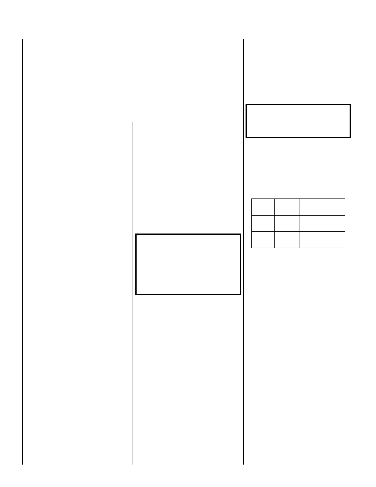
Gas Orifice
Type Size Elevation
0 - 4500'
(0 - 1370 m)
0 - 4500'
(0 - 1370 m)
Natural
Propane (0.065)
#36
(0.106)

3
NOTE: DIAGRAMS & ILLUSTRATIONS NOT TO SCALE.
Millivolt appliances may be fitted at time of
manufacture with either a Honeywell millivolt
gascontrolvalveorasSITmillivoltgascontrol
valve. Both valves have been tested with and
approved for use with these appliances and
are listed accordingly.
Test gage connections are provided on the
front of the millivolt gas control valve (identi-
fied A for the manifold side and E for inlet
pressure for SIT equipped appliances, or IN
andOUTfor Honeywell equippedappliances).
A¹⁄₈" NPT testgageconnection isprovidedon
theelectronicgascontrolvalveadjacenttothe
outlet to the main burner.
Minimuminletgaspressuretotheapplianceis
5.0incheswatercolumn(9.5MmHg)fornatu-
ral gas and 11 inches water column (20.55
MmHg) for propane for the purpose of input
adjustment.
Maximum inlet gas supply pressure to the
appliance is 10.5 inches water column (19.95
MmHg) for natural gas and 13.0 inches water
column (24.25 MmHg) for propane.
The appliance must be isolated from the gas
supplypipingsystem(byclosingitsindividual
manual shut-off valve) during any pressure
testingofthegas supply piping systemattest
pressures equal to or less than ¹⁄₂ psig (3.5
kPa).
Theappliance and itsindividual shut-offvalve
must be disconnected from the gas supply
piping system during any pressure testing of
that system at pressures in excess of ¹⁄₂ psig
(3.5 kPa).
These appliances must not be connected to a
chimney or flue serving a separate solid fuel
burning appliance.
WARNING: FAILURE TO COMPLY WITH
THEINSTALLATIONANDOPERATING IN-
STRUCTIONS PROVIDED IN THIS DOCU-
MENTWILLRESULTINANIMPROPERLY
INSTALLED AND OPERATING APPLI-
ANCE, VOIDING ITS WARRANTY. ANY
CHANGE TO THIS APPLIANCE AND/OR
ITS OPERATING CONTROLS IS DANGER-
OUS. IMPROPERINSTALLATIONORUSE
OF THIS APPLIANCE CAN CAUSE SERI-
OUS INJURY OR DEATH FORM FIRE,
BURNS, EXPLOSION OR CARBON MON-
OXIDE POISONING.
Carbon Monoxide Poisoning: Early signs of
carbon monoxide poisoning are similar to
thefluwithheadaches,dizzinessand/ornau-
sea. If you have these signs, obtain fresh air
immediately. Turn off the gas supply to the
appliance and have it serviced by a qualified
professional, as it may not be operating
correctly.
WARNING: B-VENTAPPLIANCESARENOT
DESIGNED TO OPERATE IN NEGATIVELY
PRESSUREDENVIRONMENTS(PRESSURE
WITHIN THE HOME IS LESS THAN PRES-
SURES OUTSIDE). SIGNIFICANT NEGA-
TIVELY PRESSURED ENVIRONMENTS
CAUSED BY WEATHER, HOME DESIGN,
OR OTHER DEVICES MAY IMPACT THE
OPERATION OF THESE APPLIANCES.
NEGATIVE PRESSURES MAY RESULT IN
POOR FLAME APPEARANCE, SOOTING,
DAMAGE TO PROPERTY AND/OR SEVERE
PERSONAL INJURY. DO NOT OPERATE
THESEAPPLIANCESINNEGATIVELYPRES-
SURED ENVIRONMENTS.
WARNING: CHILDREN AND ADULTS
SHOULD BE ALERTED TO THE HAZARDS
OFHIGHSURFACETEMPERATURES.USE
CAUTION AROUND THE APPLIANCE TO
AVOID BURNS OR CLOTHING IGNITION.
YOUNG CHILDREN SHOULD BE CARE-
FULLY SUPERVISED WHEN THEY ARE IN
THE SAME ROOM AS THE APPLIANCE.
WARNING: DO NOT PLACE CLOTHING
OR OTHER FLAMMABLE MATERIALS
ON OR NEAR THIS APPLIANCE.
AVERTISSEMENT: SURVEILLER LES
ENFANTS. GARDER LES VÊTEMENTS,
LESMEUBLES,L'ESSENCEOUAUTRES
LIQUIDES À VAPEUR INFLAMMABLES
LOIN DE L'APPAREIL.
OPERATION AND CARE OF YOUR
APPLIANCE
1. Appliance operation may be controlled
througharemotelylocatedoptionalwallswitch.
Separate switches may provide independent
control for the remote controlled fireplace op-
eration(optionalequipment). Inlieuofremote
or remote wall switch operation, the appliance
mustbeoperateddirectlythroughthecontrols
located on the front of the valve located within
the control compartment under the removable
refractory access panel,
Figure 1
.
Figure 1
Refractory
Access Panel
SIT Valve Shown
Gas Controls
on Valve
Operation of millivolt and electronic gas con-
trolsystemsaredifferent. Beforelightingand
operatingyourappliancedetermineifyouhave
a millivolt or electronic appliance.
Refer to
Figure 1
to access the gas control compart-
ment below the lower refractory panel. Milli-
voltapplianceswillbefittedwithoneofthetwo
gas control valves shown in
Figure 2
. Appli-
ances with electronic systems will be fitted
with the electronic valve shown in
Figure 3
.
Familiarizeyourselfwiththedifferingcontrols
for the valve your appliance uses.

4NOTE: DIAGRAMS & ILLUSTRATIONS NOT TO SCALE.
WARNING: DO NOT USE ABRASIVE
CLEANERS. NEVER CLEAN THE GLASS
WHEN IT IS HOT.
CAUTION: DO NOT ATTEMPT TO TOUCH THE
DOORSWITHYOURHANDSWHILETHEFIRE-
PLACE IS IN USE. ALWAYS USE DOOR
HANDLES. DOORS WILL BECOME VERY HOT
WHEN FIREPLACE IS IN USE.
Figure 3
ON/OFF Switch
Electronic Gas
Control Valve
OFF
I
PSI
ON
CONTROL
IGNITE
Figure 2
EA
TPTH TP TH
P
I
L
O
T
P
I
L
O
T
O
N
it
O
F
F
SIT Millivolt
Valve
O
N
O
F
F
P
I
L
O
T
Spark Ignitor
Gas Control
Knob
Gas Control
Knob
Spark Ignitor
Honeywell
Millivolt Valve
To light millivolt appliances refer to the de-
tailed lighting instructions found in both En-
glish and French on pages 10 and 11 of these
instructions respectively. Millivolt and elec-
tronic appliance lighting instructions may
also be found on the pull out labels attached
to the gas control valve located within the
gascontrol compartment. Referto
Figure2
to
locate the appropriate location for the spark
ignitor used with your appliance.
2. Whenlitforthefirsttime,thisappliancewill
emit a slight odor for an hour or two. This is
due to the “burn-in” of internal paints and
lubricantsusedinthemanufacturingprocess.
3. Keep lower control compartment clean by
vacuuming or brushing at least twice a year.
More frequent cleaning may be required due
to excessive lint from carpeting, bedding ma-
terials, etc. It is important that control com-
partments, burners and circulating air pas-
sageways of the appliance be kept clean.
4. Always turn off gas to the pilot (millivolt
appliances) before cleaning. Before re-light-
ing, refer to the lighting instructions in this
manual.Instructionsare alsofoundon a pull-
outpanellocatedontheflooroftheappliance.
5. Always keep the appliance area clear and
freefromcombustiblematerials,gasolineand
other flammable liquids.
6.Remember,Millivoltapplianceshaveacon-
tinuous burning pilot flame. Exercise caution
when using products with combustible va-
pors.
7. Clean the optional glass doors only when
necessary. Wipe surface with clean, damp-
ened,soft cloth.Followwithdry,softtowelas
desired. Take care not to scratch the glass
surface.
If your appliance is equipped with an optional
remote wall switch or remote control kit the
appliancemainburnermaybeturnedonandoff
with the wall switch or remote control. If the
applianceisnotequippedwithawallorremote
control,themainburnermustbeturnedoffand
on with the gas control knob. Turn the knob
counter-clockwise from the PILOT position to
ONtolightthemainburner,andclockwisefrom
ON to PILOT to turn off the main burner.
To light electronic appliances refer to the de-
tailed lighting instructions found in both En-
glish and French on pages 12 and 13 of these
instructions respectively. Millivolt and elec-
tronicappliancelightinginstructionsmayalso
be found on the pull out labels attached to the
gas control valve located within the gas con-
trolcompartment. Ifyourapplianceisequipped
with an optional remote wall switch or remote
control kit the appliance main burner may be
turneronandoffwiththewallswitchorremote
control. Iftheappliance is notequippedwitha
wallswitch orremote control,the main burner
must be turned off and on with the gas control
switch. Toggle the switch from ON to OFF to
operate the main burner from ON to OFF.

5
NOTE: DIAGRAMS & ILLUSTRATIONS NOT TO SCALE.
WARNING: DAMPER MUST BE IN OPEN
POSITION WHEN APPLIANCE MAIN
BURNER IS OPERATING.
AVERTISSEMENT: LE REGISTRE DOIT
ÊTRE EN POSITION OUVERTE LORSQUE
LE OU LES BRULEURS PRINCIPAUX DE
L'APPEREIL FONCTIONNMENT.
Figure 5
Figure 6
WARNING: DO NOT OPERATE THE OUT-
SIDE AIR ACTUATOR UNLESS A COM-
PLETE OUTSIDE AIR VENT SYSTEM HAS
BEEN INSTALLED WITH YOUR APPLI-
ANCE.
Many appliances are equipped when installed
withanoutside(make-up)airventsystemthat
is designed to provide the appliance with out-
side make-up air for combustion when in op-
eration. The actuator for the outside air sys-
temisstandardonallappliancesbutmustnot
be operated if the complete system is not
installed. Refer to
Figure 6
. When the com-
plete outside air vent system is installed, the
installerwillremovetheactuatorlockingscrew.
If your screw is not removed and you have
reason to believe that you have a complete
outsideairsystem, contact your distributor to
have your appliance inspected for the pres-
enceofthecompletesystem. DONOTassume
thatyouhavethissysteminplacebecauseyou
havean actuatinglever presenton yourappli-
ance front face.
To provide outside air to your appliance while
itisinoperation,locatetheoutsideairactuator
along the right side of the appliance opening
(
Figure 5
).
Tooperate,pushtheendoftheactuatortothe
leftas shownin
Figure6
,until it"pops" freeof
its"locked"position. Pulltheactuatorforward
to open the combustion air door, and push it
back to close. To "lock" the outside air door
closed, ensure the actuator is pushed all the
way back, then push the end of the actuators
totherightuntilthestepintheactuatormoves
behind the appliance front face within the
slotted opening.
Damper
Closed Damper
Open
Lintel
Outside Air
Actuator
WARNING: FIREPLACES EQUIPPED
WITH OPTIONAL ACCESSORY DOORS
SHOULD BE OPERATED ONLY WITH THE
DOORS FULLY OPEN OR FULLY CLOSED
(
FIGURE 4
). THIS APPLIANCE MAY
ONLY BE FITTED WITH DOORS CERTI-
FIED FOR USE WITH THE APPLIANCE.
Fully Open or
Fully Closed
Figure 4
AVERTISSEMENT: POUR UTILISATION
UNIQUEMENT AVEC LES PORTES EN
VERRE CERTIFIÊES AVEC L'APPAREIL.
DAMPER AND OUTSIDE AIR CONTROLS
This appliance is fitted with a manually con-
trolled vent damper. The vent damper should
be closed when the appliance is not in use to
preventcoldairfromenteringthehomethrough
theventing system. Thedamper is controlled
through the use of a control lever located
within the appliance opening at the top center
in front of the firebox lintel (
Figure 5
). The
controlleversnapsintoplaceateitherextreme
ofitsrangeofmotion. Whenlockedinposition
all the way to the right, the damper is open.
Whenlocked in positionallthe waytothe left,
the damper is closed.
The damper lever actuates a switch, (see wir-
ing diagram) which will prevent the appliance
main burner from lighting unless the damper
is locked open. The appliance flue damper
must always remain open when operating.
Remove Locking Screw
and “Pop” Actuator to the
Left Before Initial Use
Outside Air
Actuator
Pull Forward to Open,
Push Back to Close

6NOTE: DIAGRAMS & ILLUSTRATIONS NOT TO SCALE.
Figure 8
Figure 7
Maintenance
The appliance and venting system should be
thoroughly inspected before initial use and at
least annually by a qualified service techni-
cian. Propermaintenanceandusewillrequire
morefrequent,lessextensiveinspectionsand
servicing by the homeowner.
Generally, annual inspections should be per-
formedbyaqualifiedservicetechnician. More
frequent periodic inspections and cleanings
shouldbeperformed by the homeowner. Any
discrepancies discovered by the homeowner
should result in a call to a qualified service
technician to effect the repair or correction.
Refertothemaintenancescheduleformainte-
nance tasks, procedures, periodicity and by
whom they should be performed.
IMPORTANT: TURNOFFGASANDANYELEC-
TRICAL POWER BEFORE SERVICING THE
APPLIANCE.
Millivolt Appliance Checkout
Thepilot flame should besteady,notliftingor
floating. Flame should be blue in color with
traces of orange at the outer edge.
The top ³⁄₈" (9 mm) at the pilot generator
(thermopile) should be engulfed in the pilot
flame. The flame should project 1" (25 mm)
beyond the hood at all three ports (
Figure 8
).
Electronic Appliance Checkout
Lighttheburner,refertotheLightilngInstruc-
tionsin thismanual. Ensure the ignitor lights
the pilot. The pilot flame should engulf the
flame rod as shown in
Figure 8
.
Withpropercareandmaintenance,yourappli-
ance will provide many years of enjoyment. If
youshouldexperienceanyproblem,firstrefer
tothetroubleshootingguideinthismanual.If
problem persists, contact your Superior dis-
tributor.
³⁄₈" Min
(9 mm)
Hood
Pilot
Nozzels
Ignitor Rod
Proper Flame
Adjustment
Hot Surface
Igniter
Flame Rod
Ground
Electrode
3/8 To 1/2 Inch
(9 mm to 13 mm)
Pilot
Nozzle
MILLIVOLT
ELECTRONIC
(SIT Pilot)

7
NOTE: DIAGRAMS & ILLUSTRATIONS NOT TO SCALE.
Periodically (After the Burning Season)
Maintenance Task Accomplishing Person Procedure
Cleaning Firebox Interior
Check Flame Patterns and Flame Height
Checking Vent System
Cleaning Optional Glass Doors
Homeowner
Homeowner
Homeowner
Homeowner
Carefullyremovelogs,Rockwoolandvolcanic
stone if used. Vacuum out interior of the
firebox. Clean firebox walls and log grate.
Replacelogs,Rockwoolandvolcanicstoneas
detailed in this manual.
Refer to
Figure 7
and verify the flame pattern
and height displayed by the appliance con-
formstothepicture. Flamesmustnotimpinge
on the logs.
Inspect the vent system at the top and at the
base(withinthefirebox)forsignsofblockage
orobstruction. Lookfor any signsofdisloca-
tion of the vent components.
Clean as necessary following the directions
providedin thismanual. DO NOT TOUCH OR
ATTEMPT TO CLEAN DOORS WHILE THEY
ARE HOT.
Maintenance Schedule
Annually (Before the onset of the Burning Season)
Maintenance Task Accomplishing Person Procedure
Inspecting/Cleaning Burner, Logs
and Controls
Check Flame Patterns and Flame Height
Inspecting/Cleaning Pilot and Burner
Checking Vent System
Appliance Checkout
Replacing Rockwool Ember Materials
Qualified Service Technician
Qualified Service Technician
Qualified Service Technician
Qualified Service Technician
Qualified Service Technician
Homeowner/Qualified Services Technician
Inspectvalve andensure it isproperly operat-
ing. Check piping for leaks. Vacuum the
controlcompartment,fireplacelogsandburner
area.
Refer to
Figure 7
and verify the flame pattern
and height displayed by the appliance con-
formstothepicture. Flamesmustnotimpinge
on the logs.
Refer to
Figure 8
. Remove any surface build-
up on pilot and burner assembly. Wipe the
pilot nozzles, ignitor/flame rod and hood. En-
surethepilotflameengulfstheflamesensoras
shown.
Inspect the vent system at the top and at the
base(withinthe firebox) forsignsofblockage
orobstruction. Look for any signs ofdisloca-
tion of the vent components.
Perform the appropriate appliance checkout
procedure detailed in this manual.
Remove old ember materials and vacuum the
screenedrockwoolplacementarea. Placenew
rockwool as described in this document.

8NOTE: DIAGRAMS & ILLUSTRATIONS NOT TO SCALE.
Figure 10
Figure 9
Step 1. Carefully position the ceramic fiber
logs and twigs over the burner as shown in
Figures9 and10
. Placethefront logovertwo
pins located at either side of the front log
platform area, charred side forward. Position
the rear log over its pins in a similar fashion.
Figure 10
details the log set showing a front
viewandtopviewofthesinglepieceassembly.
Step 2. Proper twig placement is critical to
prevent sooting. Refer to
Figure 10
and place
thetwigsasshown. Twigsshouldbeplacedin
the gaps between the flame peaks and should
be positioned so that at no time they impinge
the flames.
Step 3. Remove the rockwool from the pack-
aging and tear into nickle size pieces (
Figure
11
). Spread along the front edge of the front
burner. Do not use more than is necessary.
When properly positioned, the rockwool will
unevenlycoverapproximately 85% ofthegap
between the front burner and the grate front
face with no appreciable openings.
Figure 11
WARNING: THE SIZE AND POSITION ON
THELOG SETWASENGINEEREDTOGIVE
YOUR APPLIANCE A SAFE, RELIABLE
ANDATTRACTIVEFLAMEPATTERN. ANY
ATTEMPTTO USE A DIFFERENT LOG SET
INTHEFIREPLACEWILLVOIDTHEWAR-
RANTY AND WILL RESULT IN INCOM-
PLETE COMBUSTION, SOOTING, AND
POOR FLAME QUALITY.
WARNING: LOGS GET VERY HOT AND
WILL REMAIN HOT UP TO ONE HOUR
AFTER GAS SUPPLY IS TURNED OFF.
HANDLE ONLY WHEN LOGS ARE COOL.
TURN OFF ALL ELECTRICITY TO THE
APPLIANCE BEFORE YOU INSTALL
GRATE AND LOGS.
WARNING: THIS APPLIANCE IS NOT
MEANT TO BURN WOOD. ANY ATTEMPT
TO DO SO COULD CAUSE IRREPARABLE
DAMAGE TO YOUR APPLIANCE AND
PROVE HAZARDOUS TO YOUR SAFETY.
Logs and Rockwool Placement
TOP
FRONT
c.
d.
e.
a.
b.

9
NOTE: DIAGRAMS & ILLUSTRATIONS NOT TO SCALE.
WIRING DIAGRAMS
Wiringdiagramsareprovidedhereforreferencepurposesonly. Thisinformationisalsoprovidedonschematicsfoundonpulloutlabelslocatedwithin
the control compartment attached to the gas control valve. Two Millivolt wiring diagrams are provided here, one each for both Honeywell and SIT
equipped systems.
SIT Millivolt Wiring Diagram
* For Wall Switch Attachment Only.
If any of the original wire as supplied must be replaced, it
must be replaced with Type AWM 105°C – 18 GA. wire.
Thermopile
TH
TP TH
TP
Limit Switch
*
1. If any of the original wire as supplied must be replaced,
1. it must be replaced with Type AWM
105°C – 18 GA. wire.
2. 120V, 60Hz – Less than 3 amps.
BK
Junction Box
Transf.
120 V.
24 V
Factory Wired Field Wired
BL
Electronic Wiring Diagram (Honeywell)
(Optional ON/OFF Switch Wiring)
R
BK
BL
To Opposite Side
OPT
FAN
G
W
OPT. ACCESSORY
SWITCH
120
VAC.
BK
LIMIT
SWITCH
W
Gas Valve
B
BL
OPTIONAL
ON/OFF SWITCH
OR
WALL SWITCH
R
R
IGNITER
CONTROL
PILOT
ASSEMBLY
Break
Off Tab
R
Thermopile
TH
TP
TH
TP
Honeywell Millivolt Wiring Diagram
If any of the original wire as supplied must be replaced, it
must be replaced with Type AWM 105°C – 18 GA. wire.
TH
TPTH
TP
* For Wall Switch Attachment Only.
*
Limit
Switch
Damper
Switch

10 NOTE: DIAGRAMS & ILLUSTRATIONS NOT TO SCALE.
LIGHTING INSTRUCTIONS – MILLIVOLT
WARNING: IF YOU DO NOT FOLLOW THESE INSTRUCTIONS EXACTLY, A FIRE OR EXPLOSION
MAY RESULT CAUSING PROPERTY DAMAGE, PERSONAL INJURY OR LOSS OF LIFE.
FOR YOUR SAFETY READ BEFORE LIGHTING
•Do not use any phone in your building.
•Immediatelycall yourgas supplierfrom aneighbor’s phone.
•If your gas supplier cannot be reached, call the fire depart-
ment.
C. Use only your hand to push in or turn the gas control knob.
Never use tools. If the knob will not push in or turn by hand,
do not try to repair it, call a qualified service technician.
Force or attempted repair may result in a fire or an explosion.
D. Do not use this appliance if any part has been under water.
Immediately call a qualified service technician to inspect the
appliance and to replace any part of the control system and
any gas control which has been under water.
A. This appliance has a pilot which must be lighted with a piezo
ignitor. When lighting the pilot, follow these instructions
exactly.
B. BEFORE OPERATING smell all around the appliance area for
gas. Be sure to smell next to the floor because some gas is
heavier than air and will settle on the floor.
WHAT TO DO IF YOU SMELL GAS
•Extinguish any open flame.
•Open windows.
•Do not light any appliance.
•Do not touch any electrical switches.
TO TURN OFF GAS TO APPLIANCE
1. Turn remote wall switch “OFF.” The pilot will remain lit for
normal service.
2. For complete shutdown, turn remote wall switch to “OFF.”
3. Access the lower control compartment.
4. Depress gas control knob slightly and turn clockwise
to “OFF.” Do not force.
5. Close lower control compartment.
LIGHTING INSTRUCTIONS
1. STOP! Read the safety information above on this page.
2. Access the lower control compartment.
3. Turn remote wall switch to “OFF.”
4. Verify main line shut-off valve is open.
5. Push in gas control knob slightly and turn clockwise
to “OFF.”
Note: Knob cannot be turned from “PILOT” to “OFF”
unless the knob is pushed in slightly. Do not force.
6. Wait five (5) minutes to clear out any gas. If you then smell
gas, STOP! Follow “B” in the safety information above on
this page. If you do not smell gas, go to the next step.
7. Push in gas control knob slightly and turn counterclockwise
to “PILOT.”
8. Push in control knob all the way and hold in. Immediately
light the pilot by triggering the spark ignitor (pushing the
button) until pilot lights. Continue to hold the control knob in
for about 1 ¹⁄₂ minutes after the pilot is lit. Release knob and
it will pop back up. Pilot should remain lit. If it goes out,
repeat steps 5 through 8.
•If knob does not pop up when
released, stop and immediately call
your service technician or gas
supplier.
•If pilot will not stay lit after several
tries, turn the control knob to “OFF”
and call your service technician or
gas supplier.
9. Turn gas control knob counterclockwise to “ON.”
10. Close lower control compartment.
O
N
O
F
F
P
I
L
O
T
HONEYWELL
EA
TPTH TP TH
P
I
L
O
T
P
I
L
O
T
O
N
it
O
F
F
SIT

11
NOTE: DIAGRAMS & ILLUSTRATIONS NOT TO SCALE.
INSTRUCTIONS D’ALLUMAGE – MILLIVOLT
INSTRUCTIONS D'ALLUMAGE
7. Enfoncez légèrement le bouton de réglage du gaz et tournez-le en
sens inverse des aiguilles d’une montre jusqu’à la position de
veilleuse “PILOT”.
8. Enfoncez le bouton de réglage jusqu’au fond et gardez-le enfoncé.
Allumez immédiatement la veilleuse en déclenchant l’allume-gaz à
étincelle (en poussant le bouton) jusqu’à ce que la veilleuse
s’enflamme. Continuez de tenir le bouton de réglage enfoncé
pendant environ 90 secondes après l’allumage de la veilleuse.
Relâchez le bouton et il sortira subitement. La veilleuse devrait
rester allumée. Si elle s’éteint, répétez les étapes 5 à 8
inclusivement.
• Si le bouton ne sort pas automatiquement après avoir été relâché,
arrêtez immédiatement et téléphonez à
votre technicien de service ou à votre
fournisseur de gaz.
• Si la veilleuse refuse de rester allumée
après plusieurs tentatives, tournez le
bouton de réglage jusqu’à sa position
d’arrêt “OFF” et téléphonez à votre
technicien de service ou à votre
fournisseur de gaz.
9. Tournez le bouton de réglage du gaz en sens inverse des aiguilles
d’une montre jusqu’à sa position de marche “ON”.
10. Fermez le compartiment de contrôle du bas.
11. Au besoin, rebrancher l’appareil au courant électrique et remettre
l’interrupteur du brûleur principal à la position “ON” ou régler le
thermostat à la température désirée.
12. Si l’appareil ne fonctionne pas, suivre les instructions intitulées
“Pour fermer le gaz qui alimente l’appareil” et appeler un
technicien ou le fournisseur de gaz.
O
N
O
F
F
P
I
L
O
T
HONEYWELL
EA
TPTH TP TH
P
I
L
O
T
P
I
L
O
T
O
N
it
O
F
F
SIT
AVERTISSEMENT : SI VOUS NE SUIVEZ PAS CES INSTRUCTIONS À LA LETTRE, IL POURRAIT S’EN SUIVRE UN INCENDIE OU UNE
EXPLOSION CAUSANT DES DOMMAGES MATÉRIELS, DES BLESSURES CORPORELLES OU MÊME DES PERTES DE VIE.
POUR VOTRE SÉCURITÉ, LISEZ CES INSTRUCTIONS AVANT L’ALLUMAGE
A. Cet appareil est muni d’une veilleuse qui doit être allumée avec un
allumeur piézo-électrique. Lorsque vous allumez la veilleuse, suivre
exactement ces instructions.
B. AVANT L’ALLUMAGE: Assurez-vous que vous ne détectez aucune
odeurdegazautourdel’apareilainsiqueprèsdusol;certainsgaz,étant
plus lourds que l’air, descendent au niveau du sol.
VOICI CE QUE VOUS DEVEZ FAIRE SI VOUS DÉCELEZ UNE ODEUR
DE GAZ:
•Éteignez toute flamme visible.
•Ouvrez les fenêtres.
•N’allumez aucun appareil.
•Ne touchez à aucun commutateur électrique.
•Ne vous servez d’aucun téléphone dans votre édifice.
•Appelez immédiatement votre compagnie de gaz en utilisant le
téléphone du voisin.
•S’il vous est impossible de contacter votre compagnie de gaz,
appelez le service des incendies.
C. N’utilisez que votre main pour manipuler le bouton de réglage du
gaz. N’utilisez jamais d’outils. Si le bouton refuse de tourner ou de
bouger, n’essayez pas de le réparer. Communiquez immédiatement
avec un technicien de service qualifié. Toute tentative pour le forcer
ou le réparer, risquerait de provoquer un incendie ou une explosion.
D. Ne vous servez pas de cet appareil si l’un de ses éléments a été
immergé dans l’eau. Appelez immédiatement un technicien
compétent pour faire inspecter l’appareil et remplacer toute pièce du
système de réglage ou commande du gaz qui a été sous l’eau.
1. ARRÊTEZ! Lisez les consignes de sécurité au verso de cette plaque.
2. Ouvrez le compartiment de contrôle du bas.
3. Tournez l’interrupteur mural à la position d’arrêt “OFF”.
4. Assurez-vous que la soupape d’arrêt de la canalisation principale est
ouverte.
5. Enfoncez légèrement le bouton de réglage du gaz et tournez-le dans
le sens des aiguilles d’une montre jusqu’à la position
d’arrêt “OFF”.
Remarque: Il est impossible de tourner le bouton de “PILOT” à “OFF” à
moins qu’il ne soit légèrement enfoncé. Ne le forcez pas.
6. Attendez cinq (5) minutes pour l’evacuation du gaz. Si vous décelez
une odeur de gaz, ARRÊTEZ ! Retournez au point “B” des consignes
de sécurité au verso de cette plaque. Si vous ne remarquez aucune
odeur de gaz, passez à l’étape suivante.
1. Tournez l’interrupteur mural à la position d’arrêt “OFF”. La veilleuse
restera allumée jusqu’au retour du service normal.
2. Pour une fermeture complète, tournez l’interrupteur mural à la
position d’arrêt “OFF”.
3. Ouvrez le compartiment de contrôle du bas.
POUR FERMER LE GAZ QUI ALIMENTE L’APPAREIL
4. Enfoncez légèrement le bouton de réglage du gaz et tournez-le dans
le sens des aiguilles d’une montre jusqu’à la position
d’arrêt “OFF”. Ne forcez pas le bouton.
5. Fermez le compartiment de contrôle du bas.

12 NOTE: DIAGRAMS & ILLUSTRATIONS NOT TO SCALE.
WARNING:IFYOUDONOTFOLLOWTHESEINSTRUCTIONSEXACTLY,AFIREOREXPLOSION
MAY RESULT CAUSING PROPERTY DAMAGE, PERSONAL INJURY OR LOSS OF LIFE.
A. When lighting the appliance, follow these instructions
exactly.
B. BEFORE OPERATING smell all around the appliance area
for gas. Be sure to smell next to the floor because some
gas is heavier than air and will settle on the floor.
WHAT TO DO IF YOU SMELL GAS
•Extinguish any open flame.
•Open windows.
•Do not light any appliance.
•Do not touch any electrical switches.
•Do not use any phone in your building.
FOR YOUR SAFETY READ BEFORE LIGHTING
•Immediately call your gas supplier from a neighbor’s
phone.
•If your gas supplier cannot be reached, call the fire
department.
C. Use only your hand to turn the gas control lever. Never
use tools. If the lever will not turn by hand, do not try to
repair it, call a qualified service technician. Force or
attempted repair may result in a fire or an explosion.
D. Do not use this appliance if any part has been under
water. Immediately call a qualified service technician to
inspect the appliance and to replace any part of the
control system and any gas control which has been
under water.
LIGHTING INSTRUCTIONS — ELECTRONIC
1. For complete shut-down, turn remote wall switch to
“OFF.”
2. Open lower control compartment door.
3. Turn the ON/OFF switch to “OFF”. Do not force.
4. Close the main line shut-off valve.
5. Close lower control compartment door.
TO TURN OFF GAS TO APPLIANCE
LIGHTING INSTRUCTIONS
1. STOP! Read the safety information above on this page.
2. Turn remote wall switch to “OFF.”
3. Open lower control compartment door.
4. Verify main line shut-off valve is open.
5. Turn the ON/OFF switch to “OFF”. Do not force.
6. Wait five (5) minutes to clear out any gas. If you then
smell gas, STOP! Follow “B” in the safety information
above on this page. If you do not smell gas, go to the
next step.
7. Turn the ON/OFF switch to “ON”. Do not force.
8. Turn “ON” all electrical power to appliance (remote wall
switch).
9. Close lower control compartment door.
TO SHUT OFF
1. Turn off all electrical power to the appliance (remote wall
switch).
Front View
ON/OFF Switch
OFF
I
PSI
ON
CONTROL
IGNITE

13
NOTE: DIAGRAMS & ILLUSTRATIONS NOT TO SCALE.
INSTRUCTIONS D’ALLUMAGE — ELECTRONIC
INSTRUCTIONS D’ALLUMAGE
POUR VOTRE SÉCURITÉ, LISEZ CES INSTRUCTIONS AVANT L’ALLUMAGE
A. Lorsquevousallumezl’appareil,suivezexactementcesinstruc-
tions.
B. AVANT L’ALLUMAGE: Assurez-vous que vous ne détectez
aucune odeur de gaz autour de l’apareil ainsi que près du sol;
certains gaz, étant plus lourds que l’air, descendent au niveau
du sol.
VOICI CE QUE VOUS DEVEZ FAIRE SI VOUS DÉCELEZ UNE
ODEUR DE GAZ
•Éteignez toute flamme visible.
•Ouvrez les fenêtres.
•N’allumez aucun appareil.
•Ne touchez à aucun commutateur électrique.
•Ne vous servez d’aucun téléphone dans votre édifice.
AVERTISSEMENT: SI VOUS NE SUIVEZ PAS CES INSTRUCTIONS À LA LETTRE, IL POURRAIT S’EN SUIVRE UN INCENDIE OU
UNE EXPLOSION CAUSANT DES DOMMAGES MATÉRIELS, DES BLESSURES CORPORELLES OU MÊME DES PERTES DE VIE.
•Appelezimmédiatementvotrecompagniedegazenutilisant
le téléphone du voisin.
•S’il vous est impossible de contacter votre compagnie de
gaz, appelez le service des incendies.
C. N’utilisez que votre main pour manipuler linterrupteur “ON/
OFF” de la valve à gaz. N’utilisez jamais d’outils. Si
l’interrupteur ne bouge pas manuellement, n’essayez pas de le
réparer. Communiquez immèdiatement avec un technicien de
service qualifié. Toute tentative pour forcer l’interrupteur ou le
réparer, risquerait de provoquer un incendie ou une explosion.
D. Nevousservezpasdecetappareil sil’un deses élémentsaété
immergé dans l’eau. Appelez immédiatement un technicien
compétent pour faire inspecter l’appareil et remplacer toute
piècedusystèmederéglageoucommandedugazquiaétésous
l’eau.
1. ARRÊTEZ ! Lisez les consignes de sécurité au verso de cette
plaque.
2. Tournez l’interrupteur mural à la position d’arrêt “OFF”.
3. Ouvrez la porte du compartiment de contrôle du bas.
4. Assurez-vousquelasoupaped’arrêtdelacanalisationprincipale
est ouverte.
5. Tournezlamanettederéglagedugazàlapositiond’arrêt“OFF”.
6. Attendez cinq (5) minutes pour l’evacuation du gaz. Si vous
décelezuneodeurdegaz ARRÊTEZ! Retournezaupoint“B”des
consignes de sécurité au verso de cette plaque. Si vous ne
remarquez aucune odeur de gaz, passez à l’étape suivante.
7. Tournezlamanettederéglagedugazjusqu’àlapositiondemarche
“ON”. Ne la forcez pas.
8. Ouvrez le courant électrique (“ON”) qui alimente l’appareil
(interrupteur mural).
9. Fermez la porte du compartiment de contrôle du bas.
10. Au besoin, rebrancher l’apareil au courant électrique et
remettre l’interrupteur principal du brûleur à la position “ON”
ou régler le thermostat à la température désirée.
11. Si l’appareil ne se met pas en marche, suivre les instructions
intitulées “Pour fermer le gaz qui alimente l’appareil” et appeler
un technicien ou le fournisseur de gaz.
POUR ÉTEINDRE L’APPAREIL
1. Coupeztoutlecourantélectriquequialimentel’appareil(interrupteur
mural).
POUR FERMER LE GAZ QUI ALIMENTE L’APPAREIL
3. Tournezlamanettederéglagedugazàlapositiond’arrêt“OFF”.
Ne la forcez pas.
4. Fermez la soupape d’arrêt de la canalisation principale.
5. Fermez la porte du compartiment de contrôle du bas.
1. Pourunefermeture complète, tournez l’interrupteur mural àla
position d’arrêt “OFF”.
2. Ouvrez la porte du compartiment de contrôle du bas.
Vue de face
Interrupteur
ON/OFF
OFF
I
PSI
ON
CONTROL
IGNITE

14 NOTE: DIAGRAMS & ILLUSTRATIONS NOT TO SCALE.
TROUBLESHOOTING THE MILLIVOLT GAS CONTROL SYSTEM
1. Spark ignitor will not light
pilot after repeated
triggering of ignitor button.
2. Pilot will not stay lit after
carefully following the
lighting instructions.
3. Pilot burning, no gas to
burner, Valve knob “ON,”
Wall Switch “ON.”
4. Frequent pilot/burner outage
problem.
CORRECTIVE ACTIONSYMPTOM
A. Defective ignitor
(no spark at electrode).
B. Defective or misaligned electrode
at pilot (spark at electrode).
C. Gas supply pressure errant.
D. Pilot orifice plugged.
A. Defective pilot generator
(thermogenerator).
A. Damper closed or Damper Switch
defective.
B. Wall switch or wires defective.
C. Thermopile may not be generating
sufficient millivoltage.
D. Plugged burner orifice.
A. Pilot flame may be too low or
blowing (high) causing the pilot/
valve safety to drop out.
Check for spark at electrode and pilot; if no spark and
electrode wire is properly connected, replace ignitor.
Using a match, light pilot. If pilot lights, turn off pilot and
trigger the ignitor button again. If pilot lights, an improper
gas mixture caused the bad lighting and a longer purge
period is recommended. If pilot will not light – check gap at
electrode and pilot - should be ¹⁄₈" to have a strong spark. If
gap measures ¹⁄₈", replace pilot (
Figure 8
).
Check inlet gas pressure. It should be within the limits as
marked on the rating plate.
Clean or replace pilot orifice.
Check pilot flame, it must impinge on thermogenerator
(
Figure 8
). Clean and/or adjust pilot for maximum flame
impingementonthermogenerator.Ensurethattheconnec-
tion between the valve and thermogenerator are tight and
secure.
Ensure damper control lever is locked in the open position,
allthe way tothe right. If thedampercontrol leverislocked
intheopenpositiontroubleshootthroughStepsB.,C.andD.
below. Ifthe mainburner willstill not light, determine ifthe
damper switch is defective and replace if necessary.
Checkwallswitchandwiresforproperconnections.Jumper
wire across terminals at wall switch, if burner comes on,
replace defective wall switch. If okay, jumper wires across
wallswitchwiresatvalve,ifburnercomeson,wiresarefaulty
or connections are bad.
Check thermopile with millivolt meter. Take reading at ther-
mopile terminals of gas valve. Should read 325 millivolts
minimum with optional wall switch “OFF.” Replace faulty
thermopile if reading is below specified minimum.
Check burner orifice for stoppage and remove.
Cleanand/oradjustpilotflameformaximumflameimpinge-
ment on thermogenerator (
Figure 8
).
POSSIBLE CAUSES
Note: Before troubleshooting the gas control system, be sure external gas shut off valve (located at gas supply inlet) is in
the “ON” position.

15
NOTE: DIAGRAMS & ILLUSTRATIONS NOT TO SCALE.
TROUBLESHOOTING THE ELECTRONIC IGNITION SYSTEM
SYMPTOM POSSIBLE CAUSES CORRECTIVE ACTION
Ensure damper control lever is locked in the open position, all the way to the
right. If the damper control lever is locked in the open position troubleshoot
through Steps B., C. and D. below. If the main burner will still not light,
determine if the damper switch is defective and replace if necessary.
See Below.
Access the leads attached to the limit switch and check for continuity. If no
continuity, replace limit switch.
Disconnect the two black wires from the wire nuts. Test switch(s) for
continuity with a multimeter. If continuity is not indicated, switch(s) is
defective and must be replaced.
Note:
Before replacing “OFF/ON” switch, be sure to check wiring for loose
connections or broken wires and repair as needed.
Check main burner orifice(s) for stoppage. Clean or replace.
Check vent system for obstructions.
A. Damper closed or
Damper Switch defective.
B. Faulty Valve System.
C. Faulty limit switch.
D. “OFF/ON” or wall switch
defective.
A. Burner orifice plugged.
B. Obstructed vent system.
1. Burner will not light.
2. Burners come “ON” but
go “OFF.”
Note:Beforetroubleshooting,besurethattheappliancemainlinegasshut-offvalve,thegascontrolvalveandthewallswitchareinthe“ON”position.
Important: Valve system troubleshooting should only be accomplished by a qualified service technician.
• Turn Off Gas Supply
• Assure Valve Switch Is In ON Position
• Disconnect Control Harness
• Set Thermostat To Call For Heat
• Check For Proper Voltage At Control Harness
(See Insert A). Voltage Should Be 24V
Between Thermostat Or Pressure Switch
And 24V Common And 24V Hot.
• Line Voltage Power
• Low Voltage Transformer
• Limit Controller
• Thermostat
• Wiring
2
CHECK
START
2
1
NO
• Plug Control Harness Into Valve. Wait For
Internal Check Delay.
YES
• Igniter Warms Up And Glows Red. • With Pilot Burner Cable Connected, Measure
Voltage At Valve HSI Element Output. 24V
Nominal. (See Insert B)
NO
• Replace Igniter/Flame Rod Assembly.
YES
• Replace Valve.
NO
• Turn On Gas Supply. • Pilot Burner Lights. • Check That Pilot Gas Is Flowing. Wait To
Assure Plot Gas Tubing Is Purged. Recycle
Call For Heat If Necessary.
NO
YES
NO
YES
YES
1
• Measure Voltage Between 24V Hot And 24V Common
Leads To Valve Control. Must Measure At Least 19.5
VAC With Igniter Powered (See Insert A). To Identify
Proper Lead, This Check Must Be Done With The
Valve Control Connected And Igniter Powered.
• Check Transformer And
Line Volt Supply.
NO
• Replace Pilot Assembly.
YES
• Check That Pilot Flame Makes Good Contact With
Pilot Burner Flame Rod.
• Check For Good Electrical Connection Through The
Pilot Tubing.
• If Both Of The Above Are Good, Replace Igniter/Flame
Rod Assembly.
• Cycle Thermostat Off And Back On.
YES
• Main Valve Opens And Main Burner Lights. NO
YES
• System Is Okay.
YES
• Main Burner Lights. NO
2
1Igniter Will Cycle Off And Back On Once During
The 90 Second Ignition Trial. All Voltage
Measurements Must Be Taken While The Igniter
Is Powered.
When Measured Voltage At Connections, Use
Care To Assure Terminals Are Not Damaged.
• Replace Valve.
• Replace Valve.
Igniter Terminals
Insert B
24 Volt Hot
End View Of
Control Harness
Connector
24 Volt
Common
24 Volt
Switched
Check For Damaged Or Missing Terminals
In Connector
Insert A

16 NOTE: DIAGRAMS & ILLUSTRATIONS NOT TO SCALE.
WARRANTY
Your gas appliance is covered by a limited
twenty year warranty. You will find a copy of
the warranty accompanying this manual.
Pleasereadthewarrantytobefamiliarwithits
coverage.
Retainthismanual.Fileitwithyourotherdocu-
ments for future reference.
REPLACEMENT PARTS
Acompletepartslistisfoundattheendofthis
manual. Use only parts supplied from the
manufacturer.
Normally, all parts should be ordered through
yourSuperiordistributorordealer.Partswillbe
shipped at prevailing prices at time of order.
When ordering repair parts, always give the
following information:
1. The model number of the appliance.
2. The serial number of the appliance.
3. The part number.
4. The description of the part.
5. The quantity required.
6. The installation date of the appliance.
If you encounter any problems or have any
questions concerning the installation or appli-
cation of this system, please contact your dis-
tributor.Forthenameofyournearestdistribu-
tor contact:
SUPERIOR FIREPLACE
4325 Artesia Avenue
Fullerton, CA 92633
(714) 521-7302
PRODUCT REFERENCE INFORMATION
Werecommendthat you record thefollowingimportantinformationaboutyourfireplace. Please
contact your Superior dealer for any questions or concerns. For the number of your nearest
Superior dealer, please call 800-731-8101
Your Fireplace's Model Number _______________________________________
Your Fireplace's Serial Number ________________________________________
The Date On Which Your Fireplace Was Installed __________________________
The Type of Gas Your Fireplace Uses ___________________________________
Your Dealer's Name_________________________________________________

17
NOTE: DIAGRAMS & ILLUSTRATIONS NOT TO SCALE.
Remote Control System (Standard) 75L66 RCK-S
ACCESSORY COMPONENTS
Touch-Up Paint Kit 81L30 FTPK-B
86L33 42 ABF
86L34 42 ABF-BB
Bi-Fold Doors 86L35 42 ABF-P
Bi-Fold Doors
Your appliance can be fitted with beautiful bi-
fold doors. Model ABF doors are available for
use with these appliances. Doors are easily
fitted to the fireplace opening. Model 42 ABF
doors come with standard black finish. Model
42 ABF-BB doors have a beautiful bright brass
finish. Model42 ABF-Pdoors have a platinum
finish.
Touch-Up Paint Kit
Repairofminor scratchesanddiscoloration of
the appliance black painted surfaces may be
accomplished with the touch-up paint kit.
Standard Remote Control System
(Model RCS-S)
The Model RCK-S (Standard) Remote Control
System, features a simplistic on/off control
functionfor the fireplace. Thismodel includes
ahand-heldtransmitter,aremotereceiverwith
wall-mount coverplate and all hardware re-
quired to install the unit. The remote receiver
can be wall or hearth mounted.
Thetransmitter hasON andOFF functionsthat
are activated by pressing either button on the
face of the transmitter. When a button on the
transmitterispressed,asignallightilluminates
briefly to verify that a signal has been sent.
The Model RCK-S is designed to operate with
all millivolt ignition systems, as well as elec-
tronic ignition systems. It may be installed
with use for either natural or propane gas
appliances. TheRCK-Sofferseaseofinstalla-
tion and allows you to execute on-off com-
mands to the fireplace effortlessly with one
simple motion.
The Model RCK-S comes complete with de-
tailed operating instructions.
RCK-S
SIGNAL
LIGHT
ON/OFF
BUTTONS
ON
INDICATOR
OFF
Decorative Volcanic Stone 80L42 FDVS
Bag of Rockwool 88L53 FGE
Decorative Volcanic Stone
The decorative volcanic stone, Model FDVS,
can be used to enhance the look of your appli-
ance. Spread the decorative volcanic stone
evenly around the bottom of the firebox.
Bag of Rockwool
Replacementember materialsare availablefor
use with these appliances. Order a bag of
Rockwool, Model FGE to replace ember mate-
rials as part of the periodic maintenance of the
appliance.
Twin Pane Doors
Yourappliance canbefittedwithbeautifultwin
panedoors. Model TPA doors areavailablefor
use with these appliances. Model TPA doors
areeasilyfittedtothefireplaceopening. Model
42TPA-BB doors have a beautifulbright brass
finish.
To ensure warranty and to prevent a potential
fire hazard, do not use any other doors on
these appliances.
Twin Pane Doors 86L36 42 TPA-BB

18 NOTE: DIAGRAMS & ILLUSTRATIONS NOT TO SCALE.
REPLACEMENT PARTS LIST — MILLIVOLT
Natural Propane
No. DESCRIPTION Part No. Qty. Part No. Qty.
Gas Fireplace Assembly – – – –
1. Firescreen 161108 2 161108 2
2. Rod, Screen 498168 2 498168 2
3. Refractory, Side LB-98313A 2 LB-98313A 2
4. Refractory, Rear LB-98314A 1 LB-98314A 1
5. Refractory Access Panel LB-97223 1 LB-97223 1
6. Refractory, Base (Left) LB-97271 1 LB-97271 1
7. Refractory, Base (Right) LB-97272 1 LB-97272 1
8. Log Set, Complete 75L51 1 75L51 1
a. Log, Front 82L5401 1 82L5401 1
b. Log, Back 82L5501 1 82L5501 1
c. Log, Top Right 82L4701 1 82L4701 1
d. Log, Top Center 82L4901 1 82L4901 1
e. Log, Top Left 82L4801 1 82L4801 1
9. Burner Assembly LB-97338 1 LB-97338 1
10. Burner Orifice 18L4001 1 LB-558741 1
11. Bag of Rockwool 88L53 1 88L53 1
GAS CONTROLS — ELECTRONIC
Natural Propane
No. DESCRIPTION Part No. Qty. Part No. Qty.
30. Gas Valve - Honeywell 62L1801 1 62L1901 1
31. Pilot Assembly (Honeywell) 62L1401 1 62L1501 1
32. Transformer Assembly LB-97275 1 LB-97275 1
33. Ignitor Assembly (Kit) 87L54 1 87L54 1
GAS CONTROLS — MILLIVOLT
Natural Propane
No. DESCRIPTION Part No. Qty. Part No. Qty.
*20. Gas Valve - SIT 43K0701 1 88J5301 1
*21. Gas Valve - Honeywell 62L0501 1 62L0501 1
22. Pilot Assembly (SIT) 62L1201 1 62L1301 1
23. Pilot Generator 60J7901 1 60J7901 1
24. Electrode And Cable 74L5801 1 74L5801 1
**25. Piezo Ignitor 111061 1 111061 1
**26. Ignition Cable 902164 1 902164 1
*Appliances may be fitted at the factory with either a Honeywell or SIT Millivolt gas control valve.
**For SIT gas valve equipped appliances only.

19
NOTE: DIAGRAMS & ILLUSTRATIONS NOT TO SCALE.
REPLACEMENT PARTS
24
22
20
3
4
5
6
7
2
1
31
30
10
REF
10
21
25
26
23 33
9
811
32
c.
b.
a.
d.
e.

20 NOTE: DIAGRAMS & ILLUSTRATIONS NOT TO SCALE.
Printed in U.S.A. © 2000 by FCT
P/N 725,007M REV. N/C 08/2000 4325 Artesia Avenue • Fullerton, CA 92833
714-521-7302
FireCraft Technologies reserves the right to make changes at any time, without notice,
in design, materials, specifications, prices and also to discontinue colors, styles and
products. Consult your local distributor for fireplace code information.
This manual suits for next models
3
Table of contents
Other Firecraft Indoor Fireplace manuals


Popular Indoor Fireplace manuals by other brands


HOMEDEPOT
HOMEDEPOT S5-005 user guide

HAMPTON BAY
HAMPTON BAY Hampton H35-NG Owners & installation manual

Focal Point
Focal Point HORIZON Installation & user's instructions

RealFlame
RealFlame Elegance Series Installation & operating manual

KAL-FIRE
KAL-FIRE E-one 100 installation instructions

bemodern
bemodern 2983 Instructions for use

RealFlame
RealFlame 1750E-W quick start guide

Procom
Procom FBD32RT manual

Focal Point
Focal Point Multiflue Inset Installation and user instructions

Evonicfires
Evonicfires E800T instruction manual

Silvercrest
Silvercrest SEKU 2000 A1 operating instructions

Heat & Glo
Heat & Glo COSMO42-IFT installation manual