FireFlex FLX-PC User manual

FM-060M-0-84B
Vacuum / Pressure Controller Model FLX-PC®
Operation Manual

Page ii
FLX-PC® Vacuum / Pressure Controller
Operation Manual
FM-060M-0-84B
Manufactured by FIREFLEX Systems Inc.
1935. Lionel-Bertrand Blvd
Boisbriand, Quebec (Canada) J7H 1N8
Tel: (450) 437-3473 Toll free: (866) 347-3353
Fax: (450) 437-1930
Web Site: http://www.fireflex.com - E-Mail: [email protected]

Page iii
FLX-PC® Vacuum / Pressure Controller
Operation Manual
FM-060M-0-84B
Table of Contents
General Description ....................................................................................................................................... 1
Display in Normal Condition ......................................................................................................................... 1
LCD Display Intensity
Vacuum Pump Control .................................................................................................................................. 2
Supervisory Pressure
Forced Shutdown Reset
Low and High Pressure ................................................................................................................................. 2
Alarm Pressure .............................................................................................................................................. 2
Operation Mode .............................................................................................................................................. 2
Quick Detection of Sprinkler Opening ......................................................................................................... 2
Events History Log ........................................................................................................................................ 3
Pressure Units ................................................................................................................................................ 3
Trouble Condition .......................................................................................................................................... 3
Specifications ................................................................................................................................................. 3
Useful Conversions ....................................................................................................................................... 3
Wiring Diagrams ............................................................................................................................................ 4

Page iv
FLX-PC® Vacuum / Pressure Controller
Operation Manual
FM-060M-0-84B
Copyright © 2018 FIREFLEX Systems Inc.
All Right Reserved
Reproduction or use, without express written permission from FIREFLEX Systems Inc, of any portion of this manual is prohibited.
While all reasonable efforts have been taken in the preparation of this manual to assure its accuracy, FIREFLEX Systems Inc
assumes no liability resulting from any errors or omissions in this manual, or from the use of the information contained herein.
FIREFLEX® is a registered trade mark from FIREFLEX Systems Inc. FLX-PC® is a registered trade mark from FIREFLEX Systems Inc.
FIREFLEX Systems Inc. reserves the right to make changes to this manual and the data sheets herewith at any time, without prior
notification.

Page 1
FLX-PC® Vacuum / Pressure Controller
Operation Manual
FM-060M-0-84B
General Description
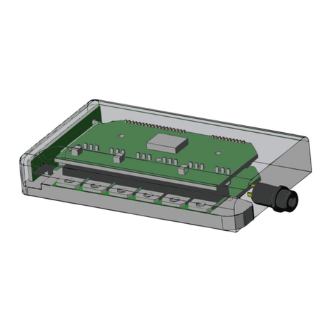
The FLX-PC® control unit is equipped with a microcontroller
based circuit that uses a piezoelectric type pressure sensor
to analyze the pressure in real time in a piping network and
perform various control operations. It includes a LCD type
display with 2 lines of 16 characters that displays the status
of the system. A single push-button on the side is used to
perform the various commands.
The FLX-PC® unit is powered by the release control panel
and consumes very little energy. Various pre-established
parameters allow to conduct supervisory and fire protection
system release via connections to the release control panel.
The FLX-PC® unit allows the control of the start-stop cycle of
the vacuum pump according to pre-established parameters.
CONTROL
PUSH-BUTTON
SERVICING CONNECTOR
19 20 21 22 23 24 25 26 27
10 11 12 13 14 15 16 17 18
1 2 3 4 5 6 7 8 9
P1
P2
P3
P4
ON
SW1-2
RV1
FACTORY SET
LCD CONTRAST ADJUSTMENT
PRESSURE TRANSDUCER
FACTORY SET
CONFIGURATION FOR
OPERATION MODE AND
FAST DETECTION
FACTORY WIRED
CONNECTION JACKS
1/2-NPT CONNECTION TOWARDS PIPING
LCD DISPLAY
FM-061H-2-8A
WIRING TOWARDS
JUNCTIONS BOX
Figure 1 - Internal arrangement of the FLX-PC unit
Display in Normal Condition
The system pressure is displayed in real time on the first line
(see PRESSURE UNITS CONVERSION section for a list of other
units of pressure).
-0.180 BAR
168:30:25 5:20
The second line shows information on the operation of the
vacuum pump. The hour meter on the left represents the
time (in hours: minutes: seconds) between the last two starts
of the pump; this gives an idea of the frequency of the pump.
The hour meter on the right represents the operation time of
the pump (in minutes: seconds) during its last start.
The limit of the time meter on the left is 9999:59:59. The one
on the right is 99:59. Each counter restarts at zero when the
limit is reached.
In the attached example, we can see that the pump starts
approximately once a week (the last two cycles of the pump
having been separated from 168 hours, 30 minutes and
25 seconds) and that the last startup time was 5 minutes,
20 seconds.
This information is useful for identifying a change of state in
the pipe network or a change in the performance of the
pump. In a normal state of supervision, the frequency and
duration of operation should be constant with time.
LCD Display Intensity
The brightness of the LCD display is kept at a low level. By
pressing the push-button momentarily, the display reaches its
full brightness; the full brightness will be kept for a period of
one minute.
The contrast of the LCD display is calibrated at the factory,
but can be changed via the RV1 adjustment potentiometer
located inside the case.

Page 2
FLX-PC® Vacuum / Pressure Controller
Operation Manual
FM-060M-0-84B
Vacuum Pump Control
The system is designed to maintain a level of vacuum in the
piping network between -0.150 BAR and -0.180 BAR. These
values are fixed and cannot be changed.
Supervisory pressure
The pump starts at -0.150 BAR and stops at -0.180 BAR.
-0.150 BAR +
When the pump is in operation, the sign [] appears to the
right of the first line.
Note: The vacuum pump will not operate if a trouble
condition is present on the FLX-PC® unit.
Forced Shutdown
The forced shutdown of the vacuum pump takes place when
the deluge valve is operated, an automatic sprinkler has
been activated or that the vacuum pump has worked for a
period of more than 35 minutes.
-0.180 BAR *
When the pump is shutdown, the sign [] is displayed to the
right of the first line.
To allow the vacuum pump to start, you must first correct the
situation and put the system in normal condition of operation.
Refer to the section B MECHANICAL SECTION of the
Operation and Maintenance Manual of the
FIREFLEX®VACTEC® system.
Once the system is back in operating condition, press and
hold the push-button for 5 seconds to restart the vacuum
pump. Release the push-button as soon as the pump starts
or until the sign [] disappears.
Note: The history display appears after 3 seconds; do not
release the push-button before the end of 5 seconds.
Low and High Pressure
A supervisory signal is transmitted to the release control
panel in the following situations:
-0.140 BAR
LOW PRESS.
When the vacuum level reaches -0.140 BAR. This can
happen if the vacuum pump does not work. Refer to the
section D VACUUM SUPPLY of the Operation and
Maintenance Manual of the FIREFLEX®VACTEC® system to
correct the situation.
If the vacuum level reached -0.220 BAR, this indicates a high
level of vacuum and this situation is abnormal. Refer to the
section D VACUUM SUPPLY of the Operation and
Maintenance Manual of the system FIREFLEX®VACTEC® to
correct the situation.
-0.220 BAR
HIGH PRESS.
Note: Supervisory signals are kept latched for a period of
5 seconds.
Alarm Pressure
Note: This section do not applies to vacuum single interlock
pre-action systems.
An alarm pressure signal is transmitted to release control
panel when the vacuum level reaches -0.130 BAR.
-0.130 BAR
ALARM PRESS.
Note: Alarm signal is kept latched for a period of 5 seconds.
Operation Mode
The FLX-PC® unit can be configured to match the different
types of interlock for a pre-action system, via switch SW1
located inside the case. This switch is configured at the
factory and should not be changed.
Quick Detection of Sprinkler Opening
The FLX-PC® unit can be configured so that it can quickly
detect an automatic sprinkler opening; this configuration is
done via the switch SW2 located inside the case. When this
mode is enabled, the letter [D] is displayed to the right of the
first line. This allows for a time of operation less than
5 seconds between the automatic sprinkler opening and the
opening of the deluge valve.
-0.160 BAR D
ALARM SPK
This operation is valid under the following conditions:
Sprinkler K Factor Network Capacity
K5.6(80) to K<11.2(161) 2000 US gal (7.57m3)
K11.2(161) to K<25.2(363) 3000 US gal (11.4m3)
K25.2(363) and bigger 4000 US gal (15.1m3)
An alarm pressure signal is transmitted to the release control
panel when a variation of the vacuum corresponding to the
opening of a vacuum sprinkler is detected.

Page 3
FLX-PC® Vacuum / Pressure Controller
Operation Manual
FM-060M-0-84B
Events History Log
The last 50 events are kept inside the FLX-PC® unit for
consultation.
To access this information, press and hold the push-button
for 3 seconds then release the push-button.
***VER: 1.0.0***
1000:45:33 HRS
The first line indicates the version of the software of the
FLX-PC® unit.
The second line shows the total operating time of the vacuum
pump. When the hour counter reaches the value of
9999:59:59, the counter returns to 0:00:00.
Note: When the 24VDC supply is removed from the
FLX-PC® unit, the hour counter returns to 0:00:00.
Press the push-button momentarily to scroll through each of
the events in history up to a maximum of 50 events. The list
will go back to the first event at the end of the last event.
***VER: 1.0.0***
1 PUMP STOP
The display will automatically return to its normal condition
after 10 seconds of inactivity of the push-button.
Note: When the 24VDC supply is removed from the
FLX-PC® unit, all events are cleared from the history.
Pressure Units
The pressure is initially displayed in BAR. It can also be
displayed in KPA, PSI or BAR/PSI. This last unit will display
the BAR when in a vacuum and the PSI under positive
pressure.
To change the unit, press and hold the push-button for
10 seconds then release the push-button.
BAR
The current unit will be displayed. Press the push-button
momentarily to scroll through the various units.
KPA
PSI
BAR/PSI
Once the unit has been selected, the display will
automatically return to its normal condition after 10 seconds
of inactivity of the push-button; the change of units will be
completed.
Note: When a unit is changed, the hour counter returns to
0:00:00 and all events are cleared from the history.
Trouble Condition
A trouble signal is transmitted to the release control panel
when the FLX-PC® unit is not powered or a defect of the
microcontroller is present.
Note: The vacuum pump will not operate if a trouble
condition is present on the FLX-PC® unit.
Note: When the 24VDC supply is removed from the
FLX-PC® unit, the hour counter returns to 0:00:00 and all
events are cleared from the history.
The opening of the FLX-PC® unit must only be performed by
a qualified technician. No operation requires to remove the
front cover.
Specifications
Voltage supply range: 20 to 28VDC
Maximum current consumption: 40mA under normal
supervisory condition; 75mA under alarm condition
Contacts rating: 30VDC, 1A (resistive)
Pump control rating: 30VDC, 45mA
Inputs rating: 30VDC, 2mA
Pressure range: -14.7 to 175PSI (-1 to 12.1BAR)
Piping connection size/material: 1/2-NPT, C836 Brass
Useful Conversions
BAR KPA PSI
-0.220 -22 -3.19
-0.180 -18 -2.61
-0.150 -15 -2.18
-0.140 -14 -2.03
-0.130 -13 -1.89
0 0 0
12.07 1207 175

Page 4
FLX-PC® Vacuum / Pressure Controller
Operation Manual
FM-060M-0-84B
Electrical Wiring
The electrical connections to the FLX-PC® unit are rooted to
the release control panel via a built-in junction box and
connected at the factory.
Connections to the FLX-PC® unit allow powering the unit, the
connection among other devices of the system, the
transmission of alarm, supervisory and trouble control signals
towards the release control panel and ultimately control of
the vacuum pump.
The FLX-PC® unit is powered via a non-resettable power
source from the release control panel. Alarm, supervisory
and trouble signals are connected to the release control
panel through dry contacts of the FLX-PC® unit. Control
contacts of the system come from the devices of the fire
protection system. The vacuum pump control is made via a
24VDC isolation relay whose contacts activate the contactor
that controls the vacuum pump.
The connections are all done via the connections of terminals
P1, P2 and P3 jacks. These jacks are spring-loaded and can
accept only a single wire. Terminals P2 and P3 are thus
redundant in order to not allow connection of more than one
wire in the same jack.
2019
P3 2221 2423 25 26 27
1110
P2 1312 1514 16 17 18
21
P1 43 65 7 8 9
MAIN VLAVE
DELUGE VALVE
OPENING
+24VDC
COM
VACUUM PIUMP
START/STOP
2019
P3 2221 2423 25 26 27
1110
P2 1312 1514 16 17 18
EOLR
EOLR
HIGH PRESSURE
ALARM
LOW PRESSURE
SUPERVISORY
HIGH PRESSURE
SUPERVISORY
TROUBLE
ALARM
SUPERVISORY
TYPICAL WIRING TOWARDS AN ALARM
CIRCUIT AND A SUPERVISORY CIRCUIT
FM-061H-2-9A
EXTERNAL CONNECTIONS
EXTERNAL
CONNECTIONS
ALARM
EOLR
SUPERVISORY
EOLR
LOW
PRESSUREALARM
HIGH
PRESSURE
TROUBLE
EQUIVALENT CIRCUIT
Figure 2 - Wiring diagrams
Table of contents
