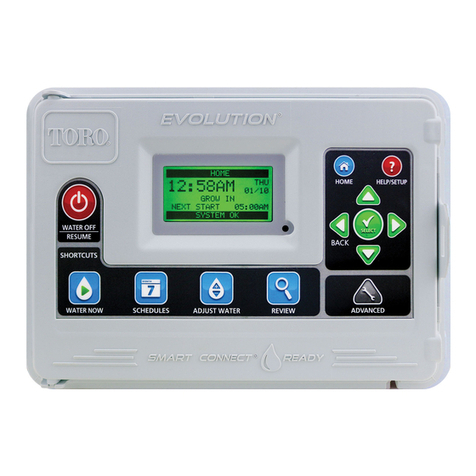
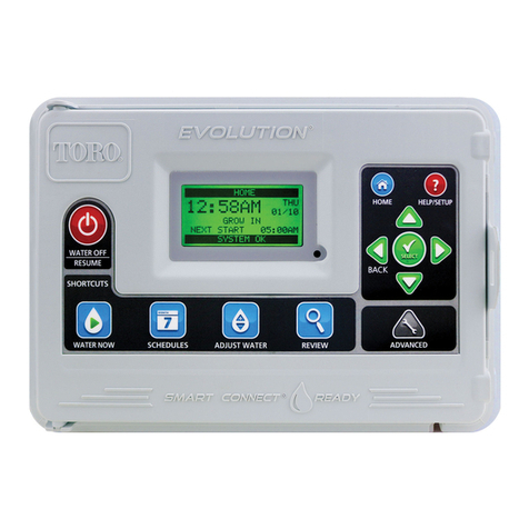
Toro EVOLUTION Series User manual

1
EVOLUTION®Series Controller
Quick Start Guide
For Complete User Guide,
Videos and Information,
Visit Toro.com/Evolution
EPA WaterSense® Certied
when used with Smart ConnectTM
Certied by
ICC-ES

2
Table of Contents
Controller Introduction
Timing Mechanism - - - - - - - - - - - - - - - - - - - - - - - - - - - - - - - - - - - - - - - - - - - - - - - - - - - - - - 4
Internal Components- - - - - - - - - - - - - - - - - - - - - - - - - - - - - - - - - - - - - - - - - - - - - - - - - - - - - - 5
Home Screen Messages - - - - - - - - - - - - - - - - - - - - - - - - - - - - - - - - - - - - - - - - - - - - - - - - - - - - 6
Setup Screen - - - - - - - - - - - - - - - - - - - - - - - - - - - - - - - - - - - - - - - - - - - - - - - - - - - - - - - - - 7
Installation
Power Supply Installation - - - - - - - - - - - - - - - - - - - - - - - - - - - - - - - - - - - - - - - - - - - - - - - - - - - 9
Zone Expansion Module Installation- - - - - - - - - - - - - - - - - - - - - - - - - - - - - - - - - - - - - - - - - - - - - - 10
Battery Installation- - - - - - - - - - - - - - - - - - - - - - - - - - - - - - - - - - - - - - - - - - - - - - - - - - - - - - 11
Valve, Pump Relay and Sensor Installation - - - - - - - - - - - - - - - - - - - - - - - - - - - - - - - - - - - - - - - - - - 11
Schedule Setup
Water Days - - - - - - - - - - - - - - - - - - - - - - - - - - - - - - - - - - - - - - - - - - - - - - - - - - - - - - - - - 12
Schedule Start Setup - - - - - - - - - - - - - - - - - - - - - - - - - - - - - - - - - - - - - - - - - - - - - - - - - - - - 13
Zone Runtimes Setup - - - - - - - - - - - - - - - - - - - - - - - - - - - - - - - - - - - - - - - - - - - - - - - - - - - - 14
Water Now
Manually Activate a Schedule - - - - - - - - - - - - - - - - - - - - - - - - - - - - - - - - - - - - - - - - - - - - - - - - 15
ManuallyActivateaSpecicZone(s) - - - - - - - - - - - - - - - - - - - - - - - - - - - - - - - - - - - - - - - - - - - - - 15
Manually Activate All Zones Test - - - - - - - - - - - - - - - - - - - - - - - - - - - - - - - - - - - - - - - - - - - - - - - 16
Water O
TurnOCurrentOperation - - - - - - - - - - - - - - - - - - - - - - - - - - - - - - - - - - - - - - - - - - - - - - - - - - 16
WaterO- - - - - - - - - - - - - - - - - - - - - - - - - - - - - - - - - - - - - - - - - - - - - - - - - - - - - - - - - - 16

3
Firmware
Firmware Update - - - - - - - - - - - - - - - - - - - - - - - - - - - - - - - - - - - - - - - - - - - - - - - - - - - - - - 17
Factory Reset- - - - - - - - - - - - - - - - - - - - - - - - - - - - - - - - - - - - - - - - - - - - - - - - - - - - - - - - - - 18
Help/Setup
Alerts - - - - - - - - - - - - - - - - - - - - - - - - - - - - - - - - - - - - - - - - - - - - - - - - - - - - - - - - - - - - -18
Contact Toro - - - - - - - - - - - - - - - - - - - - - - - - - - - - - - - - - - - - - - - - - - - - - - - - - - - - - - - - -19
Set Time/Date - - - - - - - - - - - - - - - - - - - - - - - - - - - - - - - - - - - - - - - - - - - - - - - - - - - - - - - - -19
Load From USB - - - - - - - - - - - - - - - - - - - - - - - - - - - - - - - - - - - - - - - - - - - - - - - - - - - - - - - -20
Save to USB - - - - - - - - - - - - - - - - - - - - - - - - - - - - - - - - - - - - - - - - - - - - - - - - - - - - - - - - -20
Preferences
Set Language - - - - - - - - - - - - - - - - - - - - - - - - - - - - - - - - - - - - - - - - - - - - - - - - - - - - - -21
Set Display Contrast - - - - - - - - - - - - - - - - - - - - - - - - - - - - - - - - - - - - - - - - - - - - - - - - - - -21
Set Clock Format - - - - - - - - - - - - - - - - - - - - - - - - - - - - - - - - - - - - - - - - - - - - - - - - - - - - -21
Set Date Format - - - - - - - - - - - - - - - - - - - - - - - - - - - - - - - - - - - - - - - - - - - - - - - - - - - - -22
Set the Beginning of the Week- - - - - - - - - - - - - - - - - - - - - - - - - - - - - - - - - - - - - - - - - - - - - - -22
Setting the Remote and PIN Number - - - - - - - - - - - - - - - - - - - - - - - - - - - - - - - - - - - - - - - - - - - - - - 22
Specications - - - - - - - - - - - - - - - - - - - - - - - - - - - - - - - - - - - - - - - - - - - - - - - - - - - - - - - - - 23
EPA Water Sense Qualication Criteria - - - - - - - - - - - - - - - - - - - - - - - - - - - - - - - - - - - - - - - - - - - - - 23
Toro Contact Information- - - - - - - - - - - - - - - - - - - - - - - - - - - - - - - - - - - - - - - - - - - - - - - - - - - - -23
Electronic Compatibility - - - - - - - - - - - - - - - - - - - - - - - - - - - - - - - - - - - - - - - - - - - - - - - - Back Cover
Australian Consumer Warranty Statement - - - - - - - - - - - - - - - - - - - - - - - - - - - - - - - - - - - - - - - Back Cover

4
Thank you for purchasing Toro’s new award-winning EVOLUTION
®
Series irrigation controller, delivering unprecedented control and ease-of-use of your
irrigation system!
Based on years of customer research, the EVOLUTION
®
Series controller has the perfect balance of simplicity and sophistication. The modern-day
programming, unique USB functionality, and smart capability make it an ideal choice for users seeking an advanced irrigation control without the complexity.
With the addition of Smart Connect
TM
, there are multiple options available to upgrade the controller to automatically adjust watering, or control other devices
such as lighting or water features. Using the Smart Connect
TM
Weather Sensor, the EVOLUTION
®
controller meets the requirements of the
EPA WaterSense
®
Program. You can even set your programs using a computer by utilizing the simple-to-use EVOLUTION
®
Scheduling Advisor which can be
downloaded from the www.toro.com/evolution website.
If you have any questions about the controller, please call us toll-free at 1-877-345-8676 and we will be happy to help. From locations outside North America,
Controller Introduction
Timing Mechanism
1
2
3
4
5
6
7
13
12
11
10
9
8
Figure 1
1
– LCD Screen
2
– WaterOButton.Usetoturnoscheduledandmanuallyactivated
watering.Forextendedwateringo,youcanselect1-14daysor
RemainsO.
3
– WaterNowButton.Usetomanuallyactivateaschedule,specic
zone(s)orAllZonesTest.
4
– SchedulesButton.Usetosetyouractivewateringday(s),schedule
start(s)andzoneruntime(s).
5
– Adjust Water Button. Adjust your watering percentage per schedule
or zone runtimes.
6
– Review Button. Use to review your schedule parameters.
7
– Advanced Button. Use to access the controller’s advanced
features from zone and schedule details to sensor setup and controller
diagnostics.
8
– Home Button. Use to display the controller’s activity and alert messages.
9
– Help/Setup Button. Use to access and clear alerts, set the controller’s time and date, locate Toro contact information and local service information, as
well as modify controller preferences such as the display language and time and date format. Use Setup also to save or load a schedule to or from your
USB thumb drive.
10
– Up and Down Arrow Buttons. Use to navigate up or down through the menu items. They are also used to modify parameters.
11
– Left and Right Arrow Buttons. Use to navigate between menu parameters. The
button is also used to revert back to previous menu selections.
12
– Select Button. Use to select a menu item or enter and save parameters.
13
–LEDIndicator.IndicatesthatWaterOisactive(constantlylit)oranAlertconditionisdetected(ashing)
.
5
Internal Components
1
– Zones and Sensor Terminals
VALVE TEST – Use this terminal to test a valve for proper function.
24VAC – 24 VAC Power Source
GND – Power Source Ground
SENSOR – Sensor Terminals
MV PUMP – Master Valve Terminal
COM – Zones’ and Master Valve Common Terminals
1, 2, 3and 4– Zone 1, Zone 2, Zone 3, and Zone 4 Terminals
2
– Zones’ 5, 6, 7 and 8 Expansion Module Socket
1
45 6
879
2 3
7
Figure 2
3
– Zones’ 9, 10, 11 and 12 Expansion Module Socket
4– Schedules USB Flash Drive Connector
5
– 9 Volt Battery Compartment
6
– Power Supply Terminal Compartment
7– Smart ConnectTM Module
(availableseparately)
8
– EMOD-4, Four-Zone Expansion Module
(availableseparately)
9
– EMOD-12, Twelve-Zone Expansion Module
(availableseparately)

6
Home Screen Messages
HOME
01:09PM WED
01/08
NEXT START 06:00AM
ALERT: PRESS HELP
A
B
C
ATitle Bar
HOME
Thebatteryiconindicatesthatthecontroller’sVACpowerisoandthetimerisrunningunderbatterypower.
Note: The9-voltbatteryisusedtoallowprogrammingwhentheVACpowersupplyiso,butitwillnotactivate
any zones.
B
Main Display
01:09PM TUES
01/08
Displays the current time, day of the week and date.
SCHEDULE A/B/C OR AUX
Indicateswhichschedule(A,BorC)orauxiliaryisassociatedwiththedisplayedstatus.IfonlyScheduleAisactive,
EVOLUTION®will not display the Schedule “A”, “B” and “C” or AUX.
SCHEDULE A GROW IN
Indicates the displayed schedule is set as Grow In. The Grow In option is set in the Schedule Details under the
Advanced menu.
NOT WATERING TODAY
Indicates that the displayed schedule will not water that day.
NOT ACTIVE TODAY
Thedisplayedauxiliaryschedule(Aux)willnotactivatethatday.
ZONE 1 00:05
Indicates that Zone 1 is active with a 5-minute remaining runtime. Pressing the Right arrow will deactivate the
runningzoneandactivatethenextzone(ifadditionalzonesarescheduled)inthescheduleregardlessoftheremaining
runtime.
WATERING COMPLETE
The displayed schedule completed its watering cycle.
SCHEDULE COMPLETE
Thedisplayedauxiliaryschedule(Aux)completeditscycle.
NEXT START 06:00AM
Indicatesthenextstarttimeofthedisplayedwateringorauxiliary(Aux)schedule.
DELAY 00:05
Indicates that the controller is performing a zone delay before the next zone in the schedule is activated. The zone
delay is set in the Schedule Details under the Advanced menu.
SOAK 00:05
Indicates that the active zone is performing a soak delay before continuing operation. The soak delay is set in the Zone
Details under the Advanced menu.
RAIN DELAY
Indicates that the rain sensor is activated and the schedule is delayed until the rain sensor dries up.
RAIN DELAY 02 DAYS
If Dryout Days is set, the controller will indicate Rain Delay until the number of Dryout Days are completed. Pressing
the Right arrowwilldeactivatetheDryoutDaysandtheSchedule(s)willcontinuenormaloperation.

7
NEXT START 06:00AM
The scroll down arrow indicates that additional information are available. Use the Down arrow to reveal the
additionalmessage(s).
FREEZE HOLD
Indicates that the measured temperature from the rain/freeze sensor or weather station is the same of less than the set
value in the FREEZE OFF menu parameter.
ET HOLD
Indicates that all scheduled watering are placed on hold due to weather condition measured by the weather station.
Scheduled watering will resume once the weather condition returns to conditions that permits watering.
CMessage Bar
ALERT: PRESS HELP
Indicates that the controller detected a condition that needs user attention. Check the alert messages in the Alerts
menu under the Help/Setup function. For a list of the Alert messages and description, please refer to the Alert
Messages section on page 22.
WATER OFF 04 DAYS
Indicatesthatscheduledwateringhasbeensuspendedfortheindicateddays.Wateringcanbeturnedofrom1–14
days,RemainsOorwilloperateatthenextscheduledstart.
SYSTEM OK
Indicates that the system is functioning as expected.
Setup Screen
Uponpowerup,theinitializationscreenwilldisplaybriey.Oninitialpowerup,theEVOLUTION®will display the SETUP screen.
This SETUP screen is only accessed during initial power up or after a factory reset is performed.
WELCOME
INITIALIZING
PLEASE WAIT . . .
SETUP
LANGUAGE ENGLISH
DATE FORMAT MM/DD/YY
CLOCK 12 HOUR
TIME 12:01AM
DATE 01/01/13
BEGIN WEEK SUNDAY
Set Language
Select the preferred display language. Select from English, Spanish, French, German, Italian or Portuguese.
Step 1 – While LANGUAGE is selected, press the Right arrow or SELECT .
Step 2 – Use the Up or Down arrowstoselectfromEnglish(default),Spanish,French,German,ItalianorPortuguese.
Press SELECT .
Step 3 – Navigate to the next item or press the HOME button to return to the main screen if setup is complete.

8
Set Date Format
Step 1 – Use the Down arrow to select DATE FORMAT. Press the Right arrow or SELECT .
Step 2 – Use the Up or Down arrowstoselectMM/DD/YY(Month/Day/Year)(default)orDD/MM/YY(Day/Month/Year).
Press SELECT .
Step 3 – Navigate to the next item or press the HOME button to return to the main screen if setup is complete.
Set Clock Format
Step 1 – Use the Down arrow to select CLOCK. Press the Right arrow or SELECT .
Step 2 – Use the Up or Down arrowstoselect12HOUR(default)or24HOUR.PressSELECT .
Step 3 – Navigate to the next item or press the HOME button to return to the main screen if setup is complete.
Set the Current Time
Step 1 – Use the Down arrow to select TIME. Press the Right arrow or SELECT .
Step 2 – Use the Left or Right arrows to navigate between the Hour and Minute positions. Use the Up or Down arrows to set the
correct values. Press SELECT whennished.
Step 3 – Navigate to the next item or press the HOME button to return to the main screen if setup is complete.
Set the Current Date
Step 1 – Use the Down arrow to select DATE. Press the Right arrow or SELECT .
Step 2 – Use the Left or Right arrows to navigate between the Month, Day and Year positions. Use the Up or Down arrows to set the
correct values. Press SELECT whennished.
Step 3 – Navigate to the next item or press the HOME button to return to the main screen if setup is complete.

9
Set the Beginning of the Week
Step 1 – Use the Down arrow to select BEGIN WEEK. Press the Right arrow or SELECT .
Step 2 – Use the Up or Down arrowstoselectSUNDAY(default)orMONDAYasthebeginningoftheweeklyschedule.
Press SELECT whennished.
Step 3 – Navigate to the next item or press the HOME button to return to the main screen if setup is complete.
Installation
Power Supply Installation
WARNING:ACpowerwiringmustbeinstalledandconnectedbyqualiedpersonnelonly.Allelectricalcomponentsandinstallationproceduresmust
comply with all applicable local and national electrical codes. Some codes may require a means of disconnecting from the AC power source installed in
thexedwiringandhavingacontactseparationofatleast0.120"(3mm)inthelineandneutralpoles.MakesurethepowersourceisOFFpriortoconnecting
thecontroller.Ifthesupplycordisdamaged,itmustbereplacedbythemanufacturer.itsserviceagentorasimilarlyqualiedpersoninordertoavoidahazard.
WARNING:Thisapplianceisnotintendedforusebypersons(includingchildren)withreducedphysicalsensory,ormentalcapabilities,orlackof
experience and knowledge, unless they have been given supervision or instruction concerning use of the appliance by a person responsible for their
safety. Children should be supervised to ensure that they do not play with the appliance.
Indoor and 240 VAC Outdoor Models
Indoor models and the 240 VAC Outdoor model will be pre-wired with a power cord ready to be plugged into
awallpowersocket(Figure 6).
110VAC(USandCanada)OutdoorModels
Step 1 – Route power and ground wires from a power source through a conduit and into the
EVOLUTION®cabinet.
Step 2 – Open the EVOLUTION®controller and access the internal components.
Step 3 – Remove the power compartment cover to access the transformer wiring.
Remove1/2”(12.7mm)ofinsulationfromthewireends.
Step 4 – Usingtheprovidedwirenuts,securethetransformerLine(black)wire
totheblackpowersourcewire,Neutral(white)tothewhitepowersourcewireandEquipment
Groundwire(green)tothegreenpowersourcewire.
Note: Earlier EVOLUTION®modelisequippedwithtwoEquipmentGroundwires(green).
Connect both wires to the green power source wire.
Step 5 – Install and secure the power compartment cover.
Step 6 – Apply power to the controller.
Figure 6
Figure 7
Black White Green
110 VAC Outdoor Models

10
220VAC(OutsideUSandCanada)OutdoorModels
Step 1 – Route power and ground wires from a power source through a conduit and into the
EVOLUTION®cabinet.
Step 2 – Open the EVOLUTION®controller and access the internal components.
Step 3 – Remove the power compartment cover to access the transformer terminals.
Step 4 – Remove1/2”(12.7mm)ofinsulationfromthepowersourcewireendsandinstallthebrownwire
intotheLine(L)terminal.InstallthegreenwireintotheGround( )terminalandthebluewire
intotheNeutral(N)terminal.
Step 5 – Install and secure the power compartment cover.
Step 6 – Apply power to the controller.
Zone Expansion Module Installation
The EVOLUTION®controllercanbeexpandedusingtheoptional4-zone(EMOD-4)or
12-zone(EMOD-12)modulestoaddmorezonestothesystem.
Module Installation
Step 1 – Open the EVOLUTION®controller door and control panel to access the internal
components.
Step 2 – Locate the module slot
A
and
B
. Install the module by placing the bottom hooked
standosintoslot
A
and push the module tab towards the cabinet until a positive click is
achieved. The click indicates that the module’s retaining tab is fully engaged.
Once installed, the EVOLUTION®controller will be able to read the additional zones and will
make them available for scheduling.
Note: Ifinstallingonlyonefour-stationmodule(EMOD-4),itmustbeinstalledinthe
zone 5-8 module slot.
Module Removal
Step 1 – Open the EVOLUTION®controller door and control panel to access the internal
components.
Step 2 – Hold the module as shown in Figure 11. Press the retaining tab while pulling the top of the
module away from the cabinet, then lift the module out of
the controller.
Brown Blue
Green/Yellow
(L) (N)
( )
220 VAC Outdoor Models
Figure 8
Figure 11
Figure 9 B
A
Figure 10 B
A

11
Battery Installation
The EVOLUTION®controller uses a 9-VDC battery for arm-chair programming.
Step 1 – Open the EVOLUTION®controller door and control panel to access the
internal components.
Step 2 – Locate the battery compartment at the back of the control panel.
Step 3 – Alignthepolarity(–and+)ofthebatterythenslideitintothebatterycompartmentasshownin
Figure 12.
Note: You may need to pull the battery tab forward to align the battery properly.
Valve, Pump Relay and Sensor Installation
Step 1 – Route valve wires from the valves,
master valves, pump relay and/or
sensor into the controller cabinet.
Note:18AWG(1.0mm2)
multi-wire sprinkler valve
connection cable can be used.
This cable is insulated for direct
burial and is color-coded to
simplify installation. It can be
routed directly into the controller
through the access hole provided
forvalvewireconduit(ifconduitis
notused).
Step 2 – Connect valves, master valves and
pump start relay to the valve wires
- Connect the white color-coded
wire from the cable to one wire
from each valve solenoid and/or
pumprelay.(Eitherofthetwowires
fromthesolenoidorpumprelaycanbeusedforthisconnection.)Thisconnectionwillbedesignatedasthevalvecommonwire.
Connect a separate cable wire to the remaining wire from each valve solenoid. Note the wire color-code used for each valve and the zone it
controls. You will need this information when connecting the valve wires to the controller.
Connect sensor to the valve wires - Connect any two unused color-coded wires to the sensor. Note the color-code of the sensor wires for
installation.
Step 3 – Secure all wire splices using wire nut connectors. To prevent corrosion and possible short circuits, always use an insulated wire nut, grease
caporsimilarwaterproongmethod.
Figure 12
Figure 13
1 2
MV
PUMP
SENSOR
SENSOR
COM
COM

12
Step 4 – Connectvalveswirestothecontroller-Securethevalvecommonwire(white)toeitherofthetwoterminalslabeledCOM.Securetheindividual
valve wires to the appropriate zones they control, Zone 1 valve to terminal 1, Zone 2 valve to terminal 2, etc.
Connectmastervalve/pumprelaywirestothecontroller-Securethevalvecommonwire(white)toeitherofthetwoterminalslabeledCOM.
Secure the Master Valve or Pump Relay wire to the terminal labeled MV/PUMP.
Caution: To prevent controller damage, do not connect the pump motor starter directly to the controller. Connect sensor wires to the
controller - Remove the jumper wire from the SENSORS terminals. Secure the two sensor wires to the sensor terminals. Refer to the provided
sensor instructions for further installation instructions.
Step 5 – Test for proper operation.
Schedule Setup
The EVOLUTION®controller displays only one schedule by default. See the Advanced Functions section of the full User’s Guide version to activate additional
schedules if needed.
Water Days Setup
The EVOLUTION®controllerallowsforexiblewateringbygivingyoufourscheduleoptions:7-day,Evendays,OdddaysorIntervaldays.Bydefault,the
7-day schedule is set for the schedule. To set watering days to Odd, Even or Interval, see the Advanced Functions section.
The7-dayscheduleallowsyoutoactivateorturnoanyofthedaysintheweek.Bydefault,alldaysareactive.
Step 1 – Press the SCHEDULES button.
Step 2 – (Forcontrollerswithmultipleactiveschedulesonly.)
Use the Up or Down arrows to select the Schedule you want to edit. Press SELECT .
Note: The Schedule and Zone names can be customized using the EVOLUTION®Software which can be accessed at www.toro.com/
evolution.
Step 3 – Use the Up or Down arrows to navigate to WATER DAYS. Press SELECT .
Step 4 – Use the Up or Down arrows to select WEEKDAY, ODD, EVEN or INTERVAL. Press SELECT .
Step 5 – (WEEKDAY Option)TheWEEKDAYscheduleallowsyoutoactivateorturnoanyofthedaysintheweek.Bydefault,alldaysareactive.
Use the Left or Right arrows to navigate within the days of the week. Use the Up or Down arrows to activate orturno
the day for watering. Repeat for all days of the week.
WEEKDAY
S M T W T F S
TODAY IS TUESDAY

13
(ODD Option)SelectingODDschedulewillsettheoddnumbereddaysofthecalendarasthewateringdays.
(EVEN Option)SelectingEVENschedulewillsettheevennumbereddaysofthecalendarasthewateringdays.
(INTERVAL Option)SelectingINTERVALallowsyoutosettheintervaldaysbetweenwateringcycles.Usethe
Left or Right arrows to navigate to WATER EVERY. Use the Up or Down arrows to set the desired
day interval between watering cycles, then press SELECT . While in the CURRENT DAY selection, press the
Right arrow to navigate to the CURRENT DAY parameter. Use the Up or Down arrows to set the
current day designation, then press SELECT .
Step 6 – Press the BACK arrow to return to the previous menu or HOME to return to the main screen.
Schedule Start Setup
By default, the EVOLUTION®controller is set with 1 start time set to OFF. Additional Starts can be added with a maximum of four starts per schedule. Once a
startisactivated,theschedulewillactivatetherstzone(lowestnumber).Onceitiscomplete,thesecondzonewillwater.Theschedulewillcontinueuntilall
zones with runtimes have been activated.
Step 1 – Press the SCHEDULES button. SCHEDULE
START 01:00AM
ADD START
EACH START RUNS ALL
SCHEDULED ZONES
Step 2 – (Forcontrollerswithmultipleactiveschedulesonly.)
Use the Up or Down arrows to select the Schedule you want to edit. Press SELECT .
Note: The Schedule name can be customized using the EVOLUTION®Software which can be accessed at www.
toro.com/evolution.
Step 3 – Use the Up or Down arrows to navigate to SCHEDULE STARTS. Press SELECT .
Step 4 – Use the Left or Right arrows to navigate to the start time’s Hours, Minutes and AM/PM. Use the Up or Down arrows to set
your desired start time. Press SELECT to save.
Step 5 – Navigate to ADD START to add another start time. Press SELECT . Modify the new start time as indicated in Step 3.
Step 6 – Todeleteastarttime,setthetimetoOFF.TheOFFselectionislocatedbetweenthefullhourof11:00AM/PMandthefullhourof12:00AM/
PM(23:00and00:00).
Step 7 – Press the BACK arrow to return to the previous menu or HOME to return to the main screen.
WATERS ON ODD
CALENDAR DAYS
SCHEDULE A
WATERS ON EVEN
CALENDAR DAYS
SCHEDULE A
WATERS EVERY 03 DAYS
CURRENT DAY 01
WATERS ON LAST DAY
OF INTERVAL
INTERVAL

14
Zone Runtimes Setup
The Zone Runtimes is where you select all the zones that will run in the schedule. By default, all zones are set to OFF. Modify the runtime for each zone as
necessary. Deactivate a zone by setting the runtime to OFF.
Step 1 – Press the SCHEDULES button.
Step 2 – (Forcontrollerswithmultipleactiveschedulesonly.)
Use the Up or Down arrows to select the Schedule you want to edit. Press SELECT . If only Schedule A is enabled,
move to Step 3.
Note: The Schedule and Zone names can be customized using the EVOLUTION®Software which can be accessed at
www.toro.com/evolution.
Step 3 – Use the Up or Down arrows to navigate to ZONE RUNTIMES. Press SELECT . SCHEDULE
ZONE 1 00:15
ZONE 2 00:05
3:FRONT YARD 00:15
4:BACK YARD 00:20
ZONE 5 OFF
Step 4 – Use the Up or Down arrows to navigate to the ZONE you want to set or edit.
Press the Right arrow or SELECT .
Step 5 – Use the Up or Down arrows to set the desired runtime for that particular zone. Press SELECT to save.
Step 6 – Repeat Steps 4 and 5 for the remaining Zones. Set the Zone to OFF to disable.
Step 7 – Press the BACK arrow to return to the previous menu or HOME to return to the main screen.

15
Water Now
WaterNowisusedtomanuallyactivateaschedule,zone(s),ortotestallzones.
Manually Activate a Schedule
Step 1 – Press the WATER NOW button.
Step 2 – Use the Up or Down arrows to navigate to SCHEDULE. Press SELECT . Watering will begin.
The selected schedule will run and activate all assigned zones.
(Forcontrollerswithmultipleactiveschedulesonly.)
Use the Up or Down arrows to select the Schedule you want to activate. Press SELECT .
WATER NOW
SCHEDULE A
SCHEDULE B
ZONES
Note: The Schedule name can be customized using the EVOLUTION®Software which can be accessed at
www.toro.com/evolution.
Step 3 – Press BACK to return to the previous menu or HOME to return to the main screen.
Manually Activate a Specic Zone(s) WATER NOW
ZONE 1 OFF
ZONE 2 -–:10
ZONE 3 OFF
Step 1 – Press the WATER NOW button.
Step 2 – Use the Up or Down arrows to navigate to ZONES. Press SELECT .
Note: The Zone name can be customized using the EVOLUTION®Software which can be accessed at www.toro.com/evolution.
Step 3 – Use the Up or Down arrowstoselectthespeciczonetoactivate.PresstheRight arrow or SELECT .
Step 4 – Use the Up or Down arrows to assign the zone a runtime. Press SELECT .
Thezonewillactivateuntilthespeciedruntimeexpires.Awaterdropiconisdisplayedtoindicatethatthezoneisactivelywatering.
Step 5 – Repeat Steps 3 and 4 to activate additional zones. Watering will occur in the order that the zones are entered.
Step 6 – Press the BACK arrow to return to the previous menu or HOME to return to the main screen.

16
Manually Activate All Zone Test
Step 1 – Press the WATER NOW button. WATER NOW
SCHEDULE
ZONES
ALL ZONE TEST 02:00
Step 2 – Use the Up or Down arrows to navigate to ALL ZONE TEST. Press the Right arrow or SELECT .
Step 3 – Use the Up or Down arrows to assign a runtime. Press SELECT .
Note: The EVOLUTION®controllerwillsequentiallywaterallactivezones(zoneswithruntimes)startingwithZone1.Allactivezoneswill
runthespeciedruntimeduration.
Step 4 – Press the BACK arrow to return to the previous menu or HOME to return to the main screen.
Note: AllZoneTestwillnotaecttheAUXschedule.AUXScheduleisnormallyusedforlighting.
Water O
Turn O Current Operation
Step 1 – Press the WATER OFF button. WATER OFF
RESUME WATERING
NEXT SCHEDULED START
Allcurrentlyactiveautomaticschedule(s)andmanuallyactivatedschedulesandzoneswillturno.The EVOLUTION®
controller will not run any watering schedules while the WATER OFF screen is displayed.
Step 2 – Press the HOME button. Irrigation will resume at the next automatic scheduled start time.
Water O
WATER OFF
RESUME WATERING
IN 05 DAYS
Step 1 – Press the WATEROFFbutton.Allcurrentlyactiveautomaticschedule(s)andmanuallyactivatedschedulesandzoneswillturno.
The EVOLUTION®controller will not run any watering schedules while WATER OFF is displayed. The auxiliary schedules will continue to
operate as planned.
Step 2 – Use the Up or Down arrows to assign the number of days until watering resumes. Select a delay of 1–14 days, NEXT SCHEDULED
START or REMAINS OFF. Press SELECT to enter or HOME to cancel. Pressing SELECT will save your selection and take you back to
the HOME screen.

17
Firmware
TheFirmwarefunctionallowsyoutoreviewthecontroller’srmwareversion.PressSELECT toaccessthermwareversion.
FIRMWARE
CONTROLLER 01.09
Firmware Update
USB
Figure 14
The EVOLUTION®controller’srmwarecaneasilybeupdatedbydownloadingthelatestsoftwarefrom
www.toro.com/evolution/.AUSBashdriveisneededforthisprocedure.Forfurtherhelp,lookforthe
rmwareupdatevideodemonstrationinthewebsite.
Step 1 – Connect USB to the controller. See Figure 14.
Step 2 – Click the ADVANCED button. Use the Up or Down arrows to select FIRMWARE.
Step 3 – Select UPDATE and Press SELECT . Select another UPDATE menu to start the process.
ADVANCED
SCHEDULE DETAILS
SENSORS
ADD/REMOVE DEVICE
DIAGNOSTICS
FIRMWARE
FIRMWARE
VERSION
UPDATE
FIRMWARE
CONTROLLER UPDATE
FIRMWARE
VERIFYING UPDATE
33%
Step 4 – Controllerdisplaysthermwareversioninthecontroller(current)andtheversionontheUSBdrive(update).Iftheupdateversionismoreup-
to-datethanthecurrentversion,pressSELECTonYES.Firmwareleisupdatedandastatusbarwillindicatetheprogress.Oncenished,the
controller does a soft reboot and the update process is complete.
ADVANCED
UPDATE VERIFIED
CUR. VERSION 02.10
UPDATE VERSION 02.20
CONTINUE UPDATE YES
SOFT BOOT MODE V2.20
USB DRIVE ATTACHED
WRITE: 33%
SETUP
REGION US/CAN
LANGUAGE ENGLISH
DATE FORMAT MM/DD/YY
CLOCK 12 HOUR
TIME 12:01AM
DATE 01/01/13
Step 5 – Press ADVACED,andselectFIRMWARE,thenVERSIONtoverifythermwareversion.

18
Factory Reset
Select this function to reset the controller to the factory default parameters. Schedule B, C and Auxiliary will be disabled and all FACTORY RESET
RESET TO FACTORY
DEFAULTS? YES
and all of their parameters will be cleared or set to OFF. Schedule A will be set with a WEEKDAY schedule with all 7 days active.
It will have one start time set to OFF and all zone runtimes set to OFF.
Help/Setup
Alerts
The EVOLUTION®controller always checks the system for proper function and it will provide feedback if it detects any system abnormality. The Alerts menu
allows you to view and clear detected system faults.
Alert Listings
Freeze Hold - EVOLUTION®detectedtemperaturesbelowthesetFREEZEOFFtemperaturewhenthecontrollertriedtoirrigate.(OnlyavailableifRain/Freeze
orWeathersensorisconnected).
Short - EVOLUTION®detected a short in the zone.
Overcurrent - EVOLUTION®detected an over current in the zone. Over current occurs when a terminal or combinations of terminals exceeded the
recommended current draw rating.
Low Battery - EVOLUTION®detected no battery installed or the battery’s power is low. Once the Low Battery alert is cleared, it will not display again unless a
Factory Reset is performed or the newly installed battery runs low again.
Low A/C Power - EVOLUTION®detected low or no A/C power.
Factory Reset - EVOLUTION®encountered an error that required the system to reset to the factory defaults.
Communication Error - EVOLUTION®encountered a communication error with the output zones.
Clearing an Alert
You can clear Alerts using the CLEAR ALL command to erase them all, or you can clear each alert separately.
Step 1 – Press HELP/SETUP.
Step 2 – Use the Up or Down arrows to select the Alerts. Press SELECT . ALERTS
CLEAR ALL
LOW BATTERY
Step 3 – Use the Up or Down arrows to select individual alerts or CLEAR ALL. Press SELECT .
Step 4 – Use the Up or Down arrowstoconrm(Yes)orcancel(No).PressSELECT .

19
Local Contact
This option is available only when your local distributor or dealer has programmed the local contact information in the controller.
Contact Toro CONTACT TORO
US +1(800)367-8676
TORO.COM/EVOLUTION
FOR GLOBAL SUPPORT
SEND EMAIL TO
Access Contact Toro to get the latest contact information.
Step 1 – Press HELP/SETUP.
Step 2 – Use the Up or Down arrows to select the Alerts. Press SELECT .
Set Time/Date
Step 1 – Press the HELP/SETUP button.
HELP/SETUP
ALERTS
CONTACT TORO
SET TIME/DATE
LOAD FROM USB
SAVE TO USB
Step 2 – Use the Up or Down arrows to navigate to SET TIME/DATE. Press SELECT .
Step 3 – Use the Up or Down arrows to select TIME or DATE. Navigate to the TIME or DATE parameters using the
Right arrow or SELECT . SET TIME/DATE
TIME 11:25AM
DATE 05/01/13
Step 4 – Use the Up or Down arrows to modify the TIME’s Hour and Minutes or the DATE’s Month, Day and Year
(Day,MonthandYearforInternationalFormat).
Step 5 – Press SELECT to save the changes.
Step 6 – Press the BACK arrow to return to the previous menu or HOME to return to the main screen.
Note: You can change the Time and Date format in the PREFERENCES menu. See Set Clock Format and Set Date Format sections on
page 21 and 22.

20
Load From USB
Load from USB function is used to retrieve schedules saved in a USB Flash drive.
Note:AlthoughmanyUSBashdrivesmayfunctionwellwiththeEVOLUTION®controller,thefollowingUSBspecicationsarerecommended:
• USB Version 2.0 Compliant
• 1–8GBMemorySize(Smallermemorysizewillperformfaster.)
• FAT32 File System with 1 Logical Partition
Step 1 – Plug your USB Flash drive into the EVOLUTION®USB port located at the back of the control panel. See Figure 2 on page 2.
Step 2 – Press the HELP/SETUP button.
HELP/SETUP
ALERTS
CONTACT TORO
SET TIME/DATE
LOAD FROM USB
SAVE TO USB
Step 3 – Use the Up or Down arrows to navigate to LOAD FROM USB. Press SELECT .
The EVOLUTION®controllerwilllistallavailablescheduleles.UsetheUp or Down arrows to navigate
to the desired schedule. Use the Right arrow or SELECT to load the schedule. LOAD FROM USB
ARE YOU SURE? YES
Step 4 – Use the Up or Down arrowtoselectYESfromtheconrmationwindow.
Step 5 – After the controller states Success, press the BACK arrow to return to the previous menu or HOME to return to the main screen.
Save to USB
Save to USB is used to save all the schedules that are programmed in the controller so it can be reloaded if accidentally erased. The Save to USB function is
also helpful when loading multiple controllers with the same schedule programs.
Note:AlthoughmanyUSBashdrivesmayfunctionwellwiththeEVOLUTION®controller,thefollowingUSBspecicationsarerecommended:
• USB Version 2.0 Compliant
• 1–8GBMemorySize(Smallermemorysizewillperformfaster.)
• FAT32 File System with 1 Logical Partition
Step 1 – Plug your USB Flash drive into the EVOLUTION®USB port located at the back of the control panel. HELP/SETUP
ALERTS
CONTACT TORO
SET TIME/DATE
LOAD FROM USB
SAVE TO USB
See Figure 2 on page 2.
Step 2 – Press the HELP/SETUP button.
Step 3 – Use the Up or Down arrows to navigate to SAVE TO USB. Press SELECT .
Other manuals for EVOLUTION Series
6
Table of contents
Other Toro Controllers manuals

Toro
Toro DDC Series User manual

Toro
Toro LTC PRO User manual

Toro
Toro TEMPUS DC LCD User manual

Toro
Toro Network VP 4.00 Satellite User manual

Toro
Toro GDC 200 User manual

Toro
Toro ECXTRA Operating instructions

Toro
Toro TEMPUS 53828 User manual

Toro
Toro EVOLUTION User manual

Toro
Toro Tempus Air RS4 User manual

Toro
Toro TBC WP Instruction Manual

Toro
Toro TIS-240 User manual

Toro
Toro TCM-212 User manual

Toro
Toro 114-9273 User manual

Toro
Toro TDC-100/200 User manual

Toro
Toro 119-1100 User manual

Toro
Toro Sentinel Operating instructions

Toro
Toro TMC-424 Series User manual

Toro
Toro TDC+ User guide

Toro
Toro EVOLUTION Series User manual

Toro
Toro LoRa Tempus Air MV User manual