Firefly PYX/800/250 PYX/800/250/S User manual

For use with the following models:
PYX/800/250 PYX/800/250/S PYX/800/250/1 PYX/800/250/1/S
PYX/400/250 PYX/400/250/S PYX/400/250/1 PYX/400/250/1/S
PYX/BEM/110
User manual v3.2
Pyxis Power Pack

Table of ConTenTs
Page 2 Pyxis User Manual V3.2 with accessories
4
1.1 Foreword 4
1.2 Convenons 4
1.3 Warnings 5
1.4 Standards & Regulaons 6
1.5 Disposal & Recycling 6
1.6 Firey Contact Details 6
1.7 About Firey 7
1.8 What’s In The Box? 7
8
2.1 Storage, Liing & Posioning 8
2.1.1 Storage 8
2.1.2 Liing 8
2.1.3 Posioning 8
2.2 Before Using For The First Time 8
2.3 The Pyxis Control Panel 9
2.4 Connecng Pyxis 10
2.4.1 Earth aachment: Installing the Earth Rod 10
2.4.2 Connect The Input 11
2.4.3 Connect The Output 11
12
3.1 Turning The Power On 12
3.1.1 Monitoring the Power 12
3.1.2 Turning O Pyxis 12
3.1.3 Disconnecng Pyxis 13
3.2 Charging Methods 13
3.2.1 Charging with AC/DC Mains Baery Charger 13
3.2.2 Connecng the supplied baery charger to a single Pyxis unit 14
3.2.3 Charging from 12 V DC Vehicle Accessory Socket 15
3.2.4 Charging with Fold-Array 360 Wp 12 V 16
3.2.5 Charging with Kinectrics PedGen 17

Table of ConTenTs
Page 3
Pyxis User Manual V3.2 with accessories
3.3 Care And Maintenance 17
3.3.1 General Cleaning 17
3.3.2 Cooling Fan Maintenance 18
3.3.3 Caring For The Baeries 19
3.3.4 Tesng Pyxis 19
3.4 Troubleshoong 20
21
4.1 Introducon 21
4.1.1 Stacking 21
4.1.2 Connecng The First Baery Extender Module to Pyxis 22
4.1.3 Connecng Addional Baery Extender Modules to Pyxis 22
4.1.4 Charging Baery Extender Modules 22
23
5.1 Pyxis Run Times 24
5.2 Warnings 24
5.2.1 Safety Noce Regarding The Units’ Baeries 24
Fig. 1 - Control Panel 9
Fig. 2 - Earth Rod 10
Fig. 3 - AC Output Protecon 12
Fig. 4 - Main Isolator 12
Fig. 5 - Inverter On/O Switch 12
Fig. 6 - Baery Condion Indicator 13
Fig. 7 - The Cooling Fan 18
Fig. 8 - Removing The Cooling Fan Filter 18
Fig. 9 - Cooling Fan Filter Parts 18
Fig. 10 - Pyxis with Baery Extender Module 21

Page 4 Pyxis User Manual V3.2 with accessories
1.1 Foreword
Firey take this opportunity to congratulate you on receiving your new Pyxis
Power Pack.
Designed and manufactured within the United Kingdom using quality European
sourced electrical components, your new Pyxis oers sustainable power
generaon with the reliability that you demand.
The purpose of this manual is to introduce you to Pyxis and provide you with a
guide to its safe installaon and operaon. This manual describes how your Pyxis
works, will help you with fault nding and examines what the key components
are doing and why.
1.2 Convenons
Throughout this user manual the following symbols are used:
This symbol warns of the presence of a dangerous voltage
which could cause harm to the operator.
This symbol indicates the potenal of harm to the operator,
damage to the unit or damage to connected devices.
This symbol indicates important or useful informaon.

Page 5
Pyxis User Manual V3.2 with accessories
The following terms are used in this manual to provide greater clarity:
• Firey will be referred to as “The manufacturer”.
• The Pyxis Power Pack will be referred to as “Pyxis” or “Unit”.
• Any items that consume power will be referred to as “Consumers”.
1.3 Warnings
This user manual is an important part of Pyxis. It must be
kept available to all operators and kept close to the unit so
that it can be referred to at any me.
When the unit is operang it generates potenally lethal
voltages. Work must only be performed on the unit by the
manufacturer or a qualied service engineer approved by
the manufacturer.
All items connected to the unit including distribuon cables
and boxes should be regularly checked and adhere to the
same local regulaons and standards as a regular grid-ed
mains installaon.

Page 6 Pyxis User Manual V3.2 with accessories
1.4 Standards & Regulaons
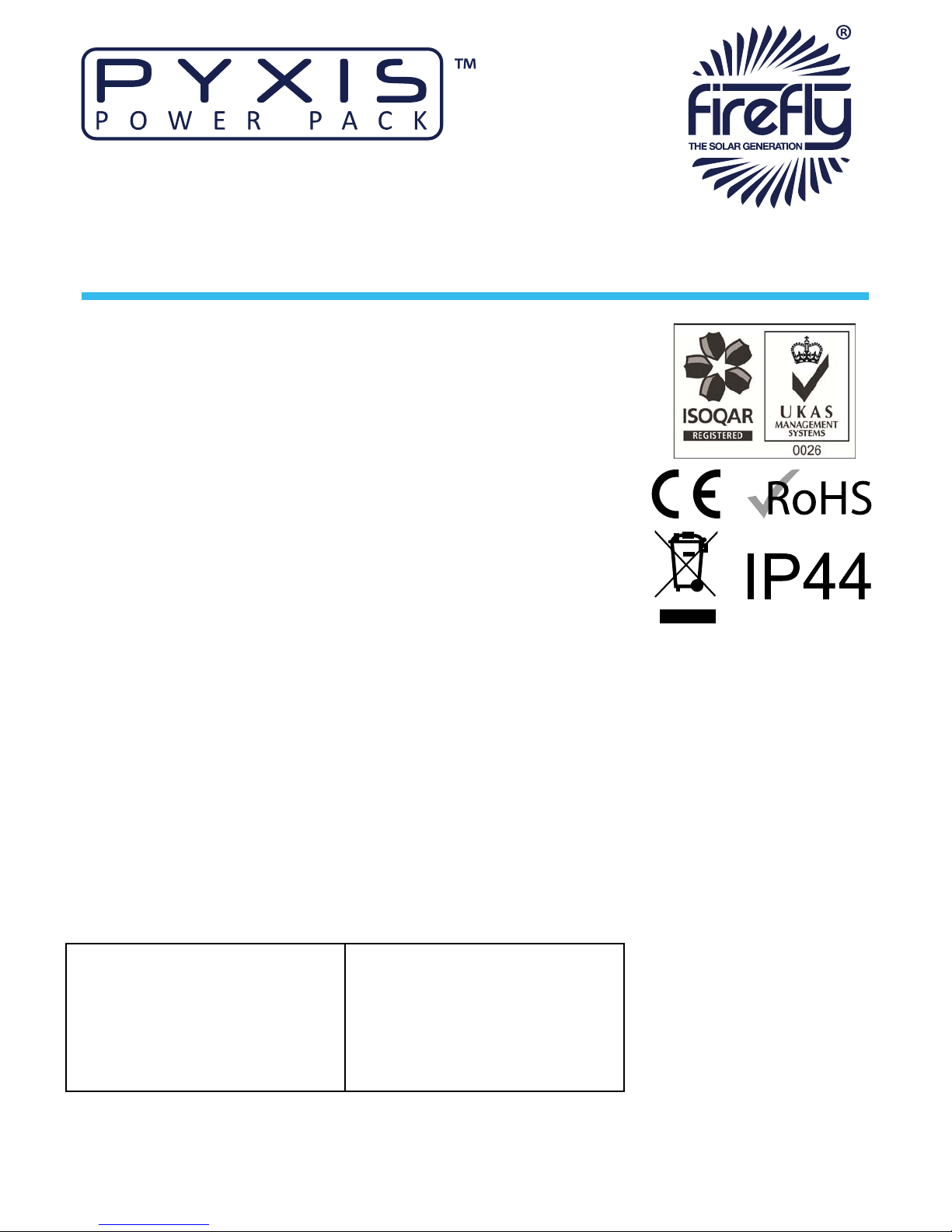
Pyxis conforms to the following standards and regulaons:
• Manufactured in compliance with ISO 9001:2008
• LVD 2006/95/EC
• 2004/108/EC
• 765/2008/EC
• 768/2008/EC
• BS 7671:2008
• IEE 17th Edion Wiring Regulaons
• BS EN 60529:1992 Degree of Protecon Provided by Enclosures Test
Procedure & Results
• Degree of Protecon Provided by Enclosures is IP44
• 3418 - Electromagnec Compability Regulaons 2006:
• EN55022:2006, EN55014-1:2006, EN61000-6-4:2007, EN61000-4-3:2002,
EN61000-4-11:2004, EN61000-4-4:2004, EN61000-4-8:1993, EN61000-4-
5:1995, EN61000-4-2:1995
1.5 Disposal & Recycling
Pyxis comprises of components that must disposed of responsibly. For the sake
of the environment many of the components within the unit can be recycled or
reused. Firey will ensure the safe decommissioning and recycling of the unit at
no charge if the unit is returned to the manufacturer. Otherwise, please contact
the manufacturer for more informaon on safe and proper decommissioning
of your Pyxis.
1.6 Firey Contact Details
Firey Solar Generators Ltd.
Unit 20 Clie Industrial Estate
South Street
Lewes
East Sussex
BN8 6JL
United Kingdom
Tel: +44 (0) 1273 40 95 95
Fax: +44 (0) 1273 40 95 96
E-mail: info@reysolar.net
Web: www.reysolar.net

Page 7
Pyxis User Manual V3.2 with accessories
1.7 About Firey
Firey is the market leading expert in the design and manufacture of o-grid,
portable Hybrid Power Soluons for temporary and permanent power
applicaons. Firey has built its highly regarded reputaon within the industry,
based on excellent customer service and product reliability. Founded in 2007 the
Company connues to develop innovave soluons to cater to the needs of its
ever growing customer sectors.
The Company oers green energy products and services that meet the needs of
environmentally concerned individuals and organisaons internaonally, that
are looking to reduce their carbon emissions caused by the use of fossil fuels
and diesel powered equipment. The unique range of renewable technology
soluons produce zero emissions, are truly silent running and eliminate the need
for fuel.
The systems are manufactured in the UK, under an ISO 9001:2008 approved
quality control system. Component suppliers are carefully selected to ensure
high levels of reliability and performance of the nal product. Installaon and
stringent tesng is carried out to ensure compliance with EU and local legislaon
where applicable.
1.8 What’s In The Box?
• Main Pyxis Unit
• AC/DC Mains Baery Charger
• User Manual

Page 8 Pyxis User Manual V3.2 with accessories
2.1 Storage, Liing & Posioning
2.1.1
1. Pyxis is designed to be used and stored outside. However, to prevent
unnecessary weathering it is recommended that the unit is stored
inside when possible.
2. It is recommended that the baery bank is charged regularly while
in storage. Refer to “3.2 Charging Methods” on page 13 for further
informaon.
3. The main isolator and output protecon switches should be switched
o when in storage and not being charged to prevent unnecessary
discharge of the baery bank.
2.1.2
Pyxis is designed to be easily liable without the need for liing gear or
machinery.
It is recommended that either Pyxis or the Baery Extender are lied from the
in-built handles by two persons.
2.1.3
1. The unit must be posioned upright on a at, solid surface. Ensure that
the unit is not at risk from being submersed in water.
2. Posion the unit out of direct sunlight where possible.
.
2.2 Before Using For The First Time
The unit’s internal baery should be charged before the unit is used for the rst
me. Follow instrucons in “3.2 Charging Methods” on page 13
The unit must remain upright at all mes.
The unit may only be installed in accordance with the
requirements of IEC 60364-4-42

Page 9
Pyxis User Manual V3.2 with accessories
1. Solar Isolator
2. AC Output Protecon
3. Baery Condion Indicator
4. Inverter On/O Switch
5. Solar Array Inputs
6. Solar Array Indicator
7. Main Isolator
8. Baery Extender Module
& 12 V DC Charging
9. Earth Point
10. AC Output Indicator
11. 230 V AC Output
Fig. 1 - Control Panel
2.3 The Pyxis Control Panel
Solar Isolator, Solar Array Inputs and Solar Array Indicator
are only available on units with the solar prep opon.

Page 10 Pyxis User Manual V3.2 with accessories
Fig. 2 - Earth Rod
2.4 Connecng Pyxis
A protecve earth must be connected to the earth
connecon point on the unit’s front panel in compliance
with applicable local standards and regulaons.
This can be done either by connecng to a suitable exisng
electrical earth, or by using an earth rod available from the
manufacturer.
The minimum gauge of earth cable to be used is 2.5mm²
An earth rod is available from the manufacturer as an
accessory.
2.4.1
1. The Earth Point of Pyxis is located on the front panel “Fig. 1 - Control
Panel” on page 9.
2. Find a suitable place to drive the earth rod “Fig. 2 - Earth Rod” into the
ground. The earth rod should be driven down at least half way into the
ground using a mallet and placed as near to the unit as possible.
3. Check the earth cable is securely connected to the rod.
4. Undo the wing nut from the unit’s earth bolt and remove one of the
washers.
5. Slide the ring terminal at the end of the earth cable onto the earth bolt.
6. Replace the washer and securely ghten the nut.

Page 11
Pyxis User Manual V3.2 with accessories
2.4.2
There are a number of means available to charge the unit : AC/DC Mains Charger,
Vehicle Accessory Socket, Solar Fold-Array, Kinectrics PedGen. Further
informaon on connecng these items is available in secon “3.2 Charging
Methods” on page 13.
Pyxis Baery Extender Modules are available to provide extended runmes. Up
to three Baery Extender Modules can be connected to a single unit. Refer to “4
Baery Extender Module” on page 21 for further informaon.
2.4.3
1. Before any power connecons are made, ensure that the AC Output
Protecon switch “Fig. 1 - Control Panel” on page 9 is switched O.
2. Plug electrical consumers in to the 230 or 110 V AC Out socket on the
control panel “Fig. 1 - Control Panel” on page 9 using a 16 A CEE Form
industrial plug.
Care must be taken to ensure that the correct connecons
are made to avoid the risk of electrocuon or possible
damage to the unit’s internal components.
The protecon provided by the unit may be impaired If the
unit is not used in a manner specied by the manufacturer.
Ensure that the cumulave power of connected consumers
does not exceed the maximum power output of your unit.
Refer to the rang plate to ascertain the unit’s maximum
power output.
All connected consumers must be t for purpose– refer to
their rang plates and manuals to ascertain the required
input.
Equipotenal earth bonding should be used with other Class
I equipment including external baery cabinets.

Page 12 Pyxis User Manual V3.2 with accessories
3.1 Turning The Power On
Once all connecons are complete, the unit is ready to be switched on. For
locaon of switches see “Fig. 1 - Control Panel” on page 9
1. Switch on the AC Output Protecon switch “Fig. 3 - AC Output
Protecon”.
2. Switch on the unit using the Main Isolator Switch “Fig. 4 - Main
Isolator”.
3. Switch on the Inverter using the Inverter On/O Switch push buon.
See “Fig. 5 - Inverter On/O Switch”.
4. The red LED indicator by the Inverter On/O Switch and the green
AC Output Indicator see “Fig. 1 - Control Panel” on page 9 will
illuminate to indicate that the unit is now on and ready to supply
power to connected consumers.
3.1.1
An analogue baery condion indicator is provided see “Fig. 6 - Baery
Condion Indicator” on page 13 to give an overview of the internal baery’s
State Of Charge. For maximum life of the baeries it is recommended that the
system is not allowed to discharge below the yellow secon of the gauge.
3.1.2
1. Switch o the Inverter using the Inverter On/O Switch push buon
“Fig. 5 - Inverter On/O Switch”.
The Main Isolator switch “Fig. 4 - Main Isolator” must be in
the on posion for the baery condion indicator to
operate.
Fig. 3 - AC Output Protecon
Fig. 4 - Main Isolator
Fig. 5 - Inverter
On/O Switch

Page 13
Pyxis User Manual V3.2 with accessories
3.1.3
1. Ensure that Pyxis is turned o “3.1.2 Turning O Pyxis” on page 12.
2. Rotate the Main Isolator switch “Fig. 4 - Main Isolator” on page 12
to the o posion.
3. Switch o the AC Output Protecon switch “Fig. 3 - AC Output
Protecon” on page 12.
4. Switch o the Solar Isolator switch if ed “Fig. 1 - Control Panel” on
page 9.
5. Disconnect the input cable(s) “Fig. 1 - Control Panel” on page 9.
6. Disconnect the output cable(s) “Fig. 1 - Control Panel” on page 9.
7. Remove the earth cable by unscrewing the Earth Point wing nut.
8. Replace the washer and wing nut onto the Earth Point bolt “Fig. 1 -
Control Panel” on page 9.
3.2 Charging Methods
Pyxis can be charged using a number of methods: AC/DC Mains Charger, Vehicle
Accessory Socket, Solar Fold-Array or Kinectrics PedGen.
3.2.1
The unit, connected Baery Extender Modules and individual Baery Extender
Modules can be charged via an external baery charger powered from either
the AC grid supply or a secondary power system.
The baery charger must be able to provide an amperage of at least 10% of the
Amp Hour (Ah) rang of the combined Pyxis & Baery Extender Modules that
are to be charged. Please contact the manufacturer for a suitable charger.
Fig. 6 - Baery
Condion Indicator

Page 14 Pyxis User Manual V3.2 with accessories
Do not use the unit while it is being charged from an
external baery charger. Otherwise damage to Pyxis and/or
external components could occur.
3.2.2
Charging Pyxis with the wrong type of baery charger may
result in over-charging of the baeries and could cause
damage to the baeries and risk of injury to the user. Only
use a charger provided by the manufacturer.
1. Connect the baery charger lead to the “Baery Extender Module
& 12 V DC Charging” socket on the front panel “Fig. 1 - Control Panel”
on page 9.
2. Follow the operaon instrucons included with the charger.
3. Baery charging and State Of Charge monitoring is handled by the
baery charger.
4. Disconnect the external baery charger when it indicates that the
baery is fully charged.
3.2.2.1 Charging the Pyxis while connected to one or more
Baery Extender Modules
The included baery charger provides enough power to
charge one unit individually. Higher output chargers suitable
for faster charging of Baery Extender Modules and mulple
units are available from the manufacturer as an accessory.
1. Connect the units using the included link leads.
2. Connect the baery charger to one of the connectors of the last unit in
the chain (it does not maer which is used).

Page 15
Pyxis User Manual V3.2 with accessories
3. The main unit and the Baery Extender Modules will be charged
simultaneously.
4. Baery charging and State Of Charge monitoring is handled by the
baery charger.
5. Disconnect the baery charger when it indicates that the baeries are
fully charged.
3.2.3
A lead suitable for charging Pyxis from a vehicle is available from the
manufacturer as an accessory. Refer to instrucons provided with the lead for
detailed instrucons.
Ensure that the unit is safely secured to the vehicle if
charging while driving.
Charging Pyxis while the engine is not running can aen the
vehicle’s baery.
3.2.3.1 Connecng
1. Start the vehicle’s engine.
2. Connect the large connector to the front panel of Pyxis.
3. Connect the small connector to the vehicle’s accessory socket.
3.2.3.2 Disconnecng
1. Disconnect the small connector from the vehicle’s accessory socket.
2. Disconnect the large connector from the front panel of Pyxis.
3. Stop the vehicle’s engine.

Page 16 Pyxis User Manual V3.2 with accessories
3.2.4
(Only available on models with Solar Prep opon)
3.2.4.1 Connecng
1. Once the array has been posioned suitably and the extension cables
safely run back to the unit, the array can be connected.
2. Before connecng the solar extension cables to Pyxis, ensure that the
Solar Isolator Switch “Fig. 1 - Control Panel” on page 9 is turned o.
3. Connect the array to the Solar Array Input on the control panel “Fig. 1 -
Control Panel” on page 9.
4. The LED indicator to the right of the inputs will illuminate to show that
the connecon has been made.
5. Ensure that the extension cable connectors are fully engaged
to avoid the risk of them pulling out easily and possible
electrocuon.
6. Once all connecons are safely made, switch on the solar isolator
switch on the control panel “Fig. 1 - Control Panel” on page 9.
7. Ensure that the main isolator is switched on. Pyxis and connected
Baery Extender Modules will only charge from the solar input with
the main isolator in the on posion.
8. The Baery Condion Indicator will move to the maximum posion.
This indicates that the baery is being charged, it does not indicate
that the baery is full. (This indicaon is dependant on the Fold-Array
receiving sucient direct sunlight).
3.2.4.2 Disconnecng
1. To disconnect the solar array from Pyxis, switch o the Solar Isolator
switch “Fig. 1 - Control Panel” on page 9.
2. Pull the Solar extension cables out from the control panel Solar Array
connectors “Fig. 1 - Control Panel” on page 9.
.
Do not connect Firey Solar Fold-Arrays with a total output
of more than 360 Wp and 12 V.

Page 17
Pyxis User Manual V3.2 with accessories
3.2.5
3.2.5.1 Connecng
1. The equipment requires the use of an MC3 to Grey SB120 Anderson
lead for connecng the regulated output of the Kinectrics Equipment.
Please contact the manufacturer to obtain a suitable lead.
2. 1 x Kinectrics unit can be connected to Pyxis.
3. Once the Kinectrics equipment has been posioned suitably, the
extension cables connected and safely run back to Pyxis (please refer
to the Kinectrics PedGen User Manual for detailed setup informaon),
the equipment can be connected.
4. Ensure that the Main Isolator switch “Fig. 1 - Control Panel” on page
9 is in the O posion.
5. Connect the lead to the Baery Extender Module & 12 V DC Charging
connector on the Pyxis control panel “Fig. 1 - Control Panel” on page
9
6. Switch on the unit using the Main Isolator switch “Fig. 1 - Control
Panel” on page 9
3.2.5.2 Disconnecng
1. Switch o the unit using the Main Isolator switch “Fig. 1 - Control
Panel” on page 9
2. Disconnect all input cables.
3.3 Care And Maintenance
3.3.1
1. Minor cleaning should be performed using a damp microbre cloth.
2. Detergents or chemicals should not be used.
Do not use a hose or pressure washer to clean Pyxis or
Baery Extender Modules.

Page 18 Pyxis User Manual V3.2 with accessories
3.3.2
3.3.2.1 Removing The Cooling Fan Dust Filter
1. Remove the outer cover by grasping both sides and pulling straight
outwards “Fig. 8 - Removing The Cooling Fan Filter” on page 18.
2. Remove the plasc mesh and white lter material from the cover.
3.3.2.2 Checking The Cooling Fan Dust Filter
In normal operang condions the cooling fan dust lter must be checked at
least monthly. When the unit is being used in dusty or sandy environments it
should be checked at least weekly. To check the dust lter:
1. Remove the Dust Filter “3.3.2.1 Removing The Cooling Fan Dust Filter”
2. Visually inspect the mesh and lter element for debris, dust or sand.
3.3.2.3 Cleaning The Dust Filter
3. Any debris and dust should be removed and/or cleaned from the lter
by brushing or light vacuuming.
4. If the lter element becomes damaged or is soiled beyond cleaning,
replacement is necessary. Contact the manufacturer for replacement
lter elements.
Operang the unit without a correctly ed Dust Filter may
allow the ingress of dust parcles and potenally damage
internal components..
3.3.2.4 Replacing The Dust Filter
1. Re-assemble the Dust Filter assembly with the black mesh towards the
outside of the unit
2. Insert the white lter element into the outer cover.
3. Re-aach the Dust Filter assembly by grasping the outer cover and
pushing it rmly back into posion over the fan unl it clicks into
posion.
4. Ensure that the black mesh is visible from outside the unit and that the
white lter element is posioned correctly covering all inlet holes.
Fig. 7 - The Cooling Fan
Fig. 8 - Removing The
Cooling Fan Filter
Fig. 9 - Cooling Fan
Filter Parts

Page 19
Pyxis User Manual V3.2 with accessories
3.3.3
Pyxis uses sealed, maintenance free baeries. The only roune care necessary
is to ensure that when not in use, the unit and any Baery Extender Modules
are charged at least once a month to keep the baery bank topped up. Refer to
“3.2 Charging Methods” on page 13 for further informaon.
3.3.4
It is recommend that the unit should be tested annually for electrical safety by
a qualied electrician.
Local regulaons may require more frequent tesng. Please refer to local
regulaons for further details.
If Pyxis fails the relevant tests, do not use or open the unit.
It must only be opened by a qualied service engineer.
It is recommended that a full service is performed every two years in order to
ascertain the condion of your system. Please contact the manufacturer for
further informaon.
Leaving the baeries in a state of discharge for extended
periods will seriously aect their performance.

Page 20 Pyxis User Manual V3.2 with accessories
3.4 Troubleshoong
The Main Isolator switch is
on, but the consumers are
not receiving any power
The AC Output Protecon
may not be switched on
Check that the AC Output
Protecon Switch “Fig. 1 -
Control Panel” on page 9
is pushed up to the on
posion.
The AC Output Protecon
Switch (“Fig. 1 - Control
Panel” on page 9) keeps
tripping
There is an electrical fault
with the consumers
connected to the AC
output
Check the electrical integrity
of the wiring and consumers
being connected to the
unit’s AC output.
Connected consumers are
drawing too much power for
the rated output of the unit
Refer to the maximum
output rang on the unit’s
rang plate and reduce the
total power draw
accordingly.
When switching the Inverter
on with the Inverter On/O
switch, its red LED
illuminates, but the green
AC Output Indicator does
not illuminate.
The AC Output Protecon
Switch is in the o posion.
Switch the AC Output
Protecon Switch “Fig. 1 -
Control Panel” on page 9
into the on posion. (Check
above points if the AC
Output Protecon switch
connues to trip.)
Input (e.g. baery charger,
solar array) is connected
and operang correctly but
the baeries are not being
charged.
The Main Isolator switch is
in the o posion.
Switch the Main Isolator
switch “Fig. 1 - Control
Panel” on page 9 into
the on posion.
This manual suits for next models
7
Table of contents