Firelight Blaze User manual
FIRELIGHT BLAZE USER INSTRUCTIONS
Description:
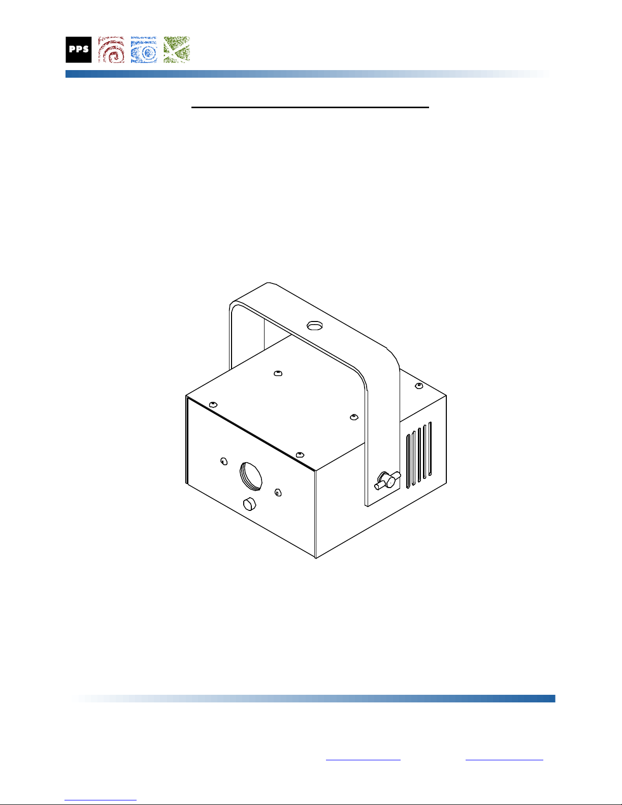
The Firelight model FL-B“Blaze” fixture is a compact, lightweight moving pattern projector which uses
advanced long lifetime LED light sources to produce high light output from a very small package. The unit is
designed to project a moving pattern of light with an irregular character resembling the appearance of fire or
flames. Two pattern wheels rotated by gear reduction motors produce the moving effect pattern with very
little light loss. The projection lens mount allows for adjustment of effect focus. The lighting industry
standard DMX control interface provides control of effect motor speed and output intensity. Installation of
glass or dichroic color filters, aperture plates, or other optics in the filter slot provided will create further
variations in the appearance of the output pattern.
Recommended Use
The Firelight Blaze fixture is intended for use in applications where the appearance or illusion of fire or flames
is desired. The fixture is intended to operate from a 120 volt AC power source using the DC power supply
provided, or an appropriate substitute. The FL-Bunit can be operated from any DC power source with
correct voltage and polarity, and an adequate current rating.
PRECISION PROJECTION SYSTEMS INCORPORATED
17508 STUDEBAKER ROAD, CERRITOS, CA 90703-3638
TELEPHONE: 562 865-8552 FACSIMILE: 562 924-7133

General Precautions
The Firelight Blaze fixture is intended for use in high ambient lighting conditions in indoor special effect
applications. The fixture may be used in applications where the appearance, illusion, or impression of fire or
flames is required. Themed attractions, museums, or restaurants can use the fixture to deliver the effect
without the hazards associated with actual fire.
CAUTION
The fixture is intended only for indoor use in dry locations. The unit is not intended for outdoor
use, or for indoor use in close proximity to an actual body of water. The fixture is not rated for,
nor protected against water splash, droplets, or mist. For outdoor or wet environment
applications, contact PPS for specifications on the optional IP65 rated enclosure.
Electrical Precautions
The Firelight Blaze projector is provided with a Class II AC power supply with a total cord length of 4 feet
minimum. The AC power supply or power cord may be connected to any standard domestic electrical outlet,
or to foreign outlets with appropriate adapters. The power supply output connector is a 2.1mm, center
positive DC power plug which mates with the input socket at the rear of the Firelight fixture. To connect the
Firelight to the power supply, install the coaxial plug into the socket at the rear of the unit. Once the DC
connector is attached, the power supply or cord may be connected to the AC power source.
WARNING
DO NOT CONNECT THE FIRELIGHT FIXTURE DIRECTLY TO ANY AC POWER SOURCE
Application of AC voltage to the fixture will cause serious damage to the fixture, which is not
covered by the fixture warranty, and may cause increased risk of electrical shock or fire,
potentially resulting in serious injury or death.
The Firelight FL-Bmodels are usually shipped with a “Universal Voltage” AC power supply
which can operate the fixture from 100 to 240 volt AC line voltage at either 50 or 60 Hertz. Do
not attempt to operate the unit or power supply from unknown or incorrect AC voltages. Do not
operate universal voltage power supplies from a dimmed AC lighting circuit.
DC Power Connections
For applications where DC power is available, the AC power supply may be omitted, and the fixture operated
directly by DC power. The recommended DC power supply must have a voltage of from 9 to 24 volts, and a
power rating of at least 30 watts. The current required will depend upon the voltage supplied. The DC
power input socket on the fixture is a standard 2.1 mm female coaxial DC socket, where the 2.1 mm center
pin is the positive connection, and the outer sleeve is negative. The output connector of the DC power supply
should be equipped with a male coaxial DC power plug, wired with correct polarity to mate with the input
socket at the rear of the Firelight fixture. WARNING
The FL-BBlaze fixture is designed to operate on 9 to 24 volt DC power. The current required
will vary inversely with the voltage supplied, with a maximum of 30 watts per fixture. Application
of AC voltage, incorrectly polarized DC voltage, or DC voltages outside of the normal range to the
fixture may cause serious damage to the power supply and to the fixture, and may cause increased
risk of electrical shock or fire, potentially resulting in serious injury or death. Do not attempt to
operate the fixture with incorrect or unknown DC supply voltages.
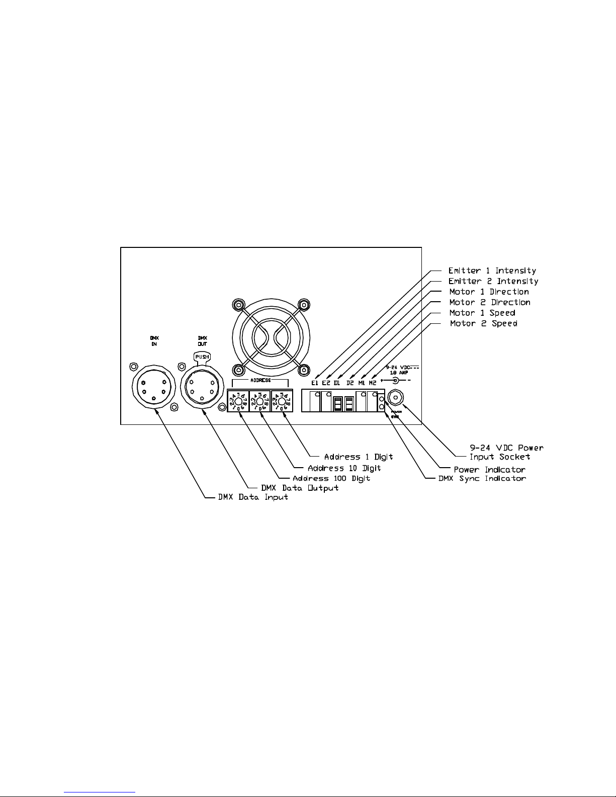
Controls and Connections
All connections and controls with the exception of the focus adjustment are located on the rear panel of the
fixture. Connections for DMX data input and output are provided using standard 5 pin male and female
“XLR” connectors, and DMX address settings are made using three rotary selector switches adjacent to the
DMX connectors. DC power is applied to the fixture using a 2.1mm coaxial DC power socket. “Power”
and DMX “Sync” indicators are located next to the power connector. Trimpots and switches to provide
manual control over motor speed, direction, and the intensity of the LED emitters are accessible on the rear
panel of the unit.
Note: Some or all of the manual trimmer controls may be inoperative depending upon the DMX
mode setting selected.
External Manual Mode Selection and Operation
When no DMX data source is available, the FL-BBlaze fixture can be set to operate in manual mode for
either demonstration purposes, or for “stand-alone” operation. Manual mode can be selected by setting the
DMX address switches to address 900 or higher. When the unit is powered up with a DMX address setting
of 900 or above (normally invalid), the fixture will revert to fully manual operation, where all LED intensity
levels and effect motor speeds are set by the trimmer controls at the rear of the unit.
Any DMX data applied to a unit operating in this “Manual Mode” will be ignored. The unit will resume
normal DMX operation when the DMX address settings are restored to within the usual range, and the power
to the unit is cycled off and on again. When the unit is powered up after the new address settings are in
place, normal DMX controlled operation will resume when suitable DMX data is applied to the fixture.

DMX Mode Selection
The FL-BBlaze fixture has internal jumpers which can be preset to operate the unit in one of four DMX
control modes. Minimal control mode allows control of fixture intensity, while full control mode allows control
over fixture intensity and effect motor speed. Depending on the fixture model, the unit may be set to use
from one to four DMX channels. The default setting for all FL-BBlaze fixtures is for four channel DMX
mode. The first two channelscontrol the intensity of the red and amber LED emitters, with two additional
channels controlling the speed of the effect drive motors.
DMX Mode Confirmation
The selected DMX mode can be confirmed without opening the unit. When power is applied to the fixture in
DMX mode, the green “Power” indicator will light immediately, and the green “Sync” indicator will flash from
one to four times depending upon the DMX Mode setting. The number of flashes corresponds to the mode,
and to the number of DMX channels required to properly control the fixture. After displaying the DMX
mode, the “Sync” indicator will then go out in the absence of DMX data, or will illuminate steadily if good
DMX data is being received.
DMX Mode Selection
The DMX mode is selected by the position of internal jumpers J7 and J8, which are located on the DMX
Interface board inside the fixture. If necessary, these settings can be altered by opening the fixture to change
the jumper settings . The fixture should be disconnected from the DC power supply before opening the unit
housing to change any jumper setting. The jumper positions for the various settings are illustrated below.
DMX Channel Assignments
The DMX channel assignments in the four available modes are defined in the following chart
Mode Channel 1 Channel 2 Channel 3 Channel 4
One Channel LED Intensity* Unused Unused Unused
Two Channels LED 1 Intensity LED 2 Intensity Unused Unused
Three Channels LED Intensity* Motor 1 Speed Motor 2 Speed Unused
Four Channels LED 1 Intensity LED 2 Intensity Motor 1 Speed Motor 2 Speed
* LED intensity in these settings will control the output of both LED driver channels, which are commonly
driven in parallel for driving high output white LED emitters, or arrays of multiple emitters.

DMX Base Address Selection
DMX base addresses are selected by setting the three DMX address switches to within the normal DMX
channel range of from 1 to 512. When the address switches are set to within this range, the fixture will
respond to DMX control data corresponding to the channels selected. The three rotary address selector
switches are set to choose the base DMX address for the unit, and the selected address is read and stored
when power is applied to the unit. Changing to a new address setting will require that power be removed
from the unit and restored before the new address setting will become functional.
The FL-BBlaze fixtures occupy from 1 to 4 consecutive DMX control channels, beginning with the channel
selected as the base address on the DMX address selection switches. For example, a unit in 2 channel mode
set to a base DMX address of 100 would occupy and respond to information on DMX channels 100 and 101.
A unit in 3 channel mode set to a DMX base address of 200 would respond to intensity control information on
DMX channel 200, with effects speed on channels 201 and 202.
Normal DMX Indicators and Operation
When power is applied to the unit in DMX mode, the green “Power” indicator will light immediately, and the
green “Sync” indicator will flash from one to four times depending upon the DMX Mode setting. The “Sync”
indicator will then illuminate steadily when valid DMX data is applied. Note that the “Sync” light is a global
indication of the presence of DMX data, and is not an indication that data specific to the address settings of
the unit are present.
When DMX data is being received, the unit will operate in response to the value of the data signals which are
transmitted on the appropriate channels. The light sources and effect motors will operate at the intensity and
speed settings as determined by the DMX data values. The unit will continue to operate in this manner until
the settings are readjusted to the users preference. The fixture is rated for continuous operation, and in
normal use, the unit will continue to display the desired output pattern until power is removed, or until the
DMX data settings are altered or reduced to minimum values.
Drop Out Tolerance
The green “Sync” indicator will respond immediately to the presence or absence of valid DMX data.
However, the fixture will continue to operate using the last valid data received before DMX data was lost for
a period of approximately 3 seconds. This data retention allows the unit to tolerate minor interruptions in the
DMX data stream caused by poor connections or brief “dropouts”. After this interval, the unit will default to
the normal “no DMX data” state, with all output channels inactive. Normal operation will resume
immediately when a valid DMX data stream is restored.
DMX Troubleshooting
If the “Sync” indicator is not steadily illuminated when DMX data is connected, then there is either a problem
with the DMX data or cables, or an internal problem with the Firelight unit. If the unit does not operate, and
the “Sync” indicator flashes constantly at a regular interval, then the DMX base address is set to an invalid
number. The “Sync” indicator will flash constantly if the base address is set to zero, or is set to a number
higher than the highest base address which will allow control of the fixture.
If the “Sync” indicator is erratic, then the DMX data connection is either intermittent due to a poor electrical
connection, or the DMX data is dropping out, which can be caused by poor connections, poor quality cables,
long data runs, or poor signal quality in general. Test the unit with different cables, or in a different location
closer to the DMX data source to determine what or where the problem is.

LED Driver Options
The Firelight Blaze fixture uses advanced high efficiency LED driver circuitry. This circuit allows the fixture
to operate from a wide range of DC input voltages, and drives two independent LED emitter channels with
individually optimized parameters.
The LED drive circuits are “switch mode” designs, which use high frequency resonant components to provide
drive current to the LED devices without the losses associated with linear control circuitry. The “charge
pump” frequency of 400 kilohertz is filtered and modulated to provide variable DC drive current to the LED
emitters.
The drive circuits can be configured to modulate the intensity of the LED emitters in any of 3 different ways.
The default control mode is the “Enhanced PWM” mode, which controls the intensity of the LED emitters by
adjusting both the LED current and the LED duty cycle to obtain excellent dimming performance, especially
at low intensity levels.
The other intensity control modes are “PWM Mode”, which modulates only the On / Off duty cycle of the
LED for intensity control, with the LED emitter always operated at a constant current, which assures a
constant color temperature. The frequency for all PWM duty cycle variation is 2.5 kilohertz, which is far
above the rate which can be perceived as a visual flicker, and is also well above the rate which may become
visible on most film or video camera systems. The PWM modulation frequency is synchronized for the two
LED drive channels, so that no inter-modulation effects are generated.
The remaining control mode is the “Analog Mode”, where the LED emitter is always active, but the LED
drive current is modulated to control the emitter intensity. In this mode, there is no PWM modulation of the
LED output, which will appear constant to the eye, and also on high speed film or video systems. All control
modes feature a positive LED shutoff at minimum intensity settings.
The default “Enhanced PWM” mode is suitable for almost all installations, but the other LED drive modes are
available for specialized applications. Altering the LED drive mode will require disassembly of the fixture, so
users are advised to contact PPS in advance if LED drive modes other than the default are needed to best
suit your application.
LED Current Options
Each channel of the LED drive circuit is capable of driving LED emitters within the range of from .75 to 2.5
amperes. The maximum drive current for each channel is preset during manufacturing to match the
maximum current rating of the LED emitters installed in each fixture.
The maximum current is determined by the settings of a group of solder jumpers for each LED channel.
These jumper settings should not be altered, unless the LED emitters installed in the fixture have been
replaced with others with a different maximum current rating. Altering the LED current setting will require
disassembly of the fixture. Users are advised to contact PPS in advance if the application requires changing
the LED emitters, and making a corresponding adjustment to the maximum LED drive current levels.
CAUTION
Resetting the LED current jumpers to a higher current level may significantly reduce the LED
lifetime, and will void the warranty on the fixture.

Mounting
The Firelight fixture incorporates a mounting yoke with a 1/2" hole at the center for hanging the instrument.
The Firelight is normally attached to a mounting “C-clamp” or other stable means of support using the yoke
mounting hole and an appropriate bolt and washer. The unit can be mounted in any orientation, keeping in
mind that intensity and speed adjustments along with power and DMX data connections must be made at the
rear of the unit, and focus adjustments from either the top or bottom.
Supplementary mounting accessories such as safety cables are recommended, and may be required when
the fixture is mounted above occupied areas. The user is responsible for mounting the instrument in a
safe and secure manner. Please consult with local public or workplace safety authorities to determine if
any additional safety restraints, such as safety wires or cables may be required.
Aiming
The instrument can be pointed using the mounting hole on the yoke as a directional pivot. Tightening the
mounting fastener will lock the instrument in that axis. The mounting yoke attaches to the sides of the
instrument with two thumbscrews. Loosening the thumbscrews allows adjustment of the instrument in
elevation. Tightening the thumbscrews locks the elevation axis. The user is responsible for mounting the
instrument in a safe and secure manner. Please consult with local public or workplace safety authorities to
determine if any additional safety restraints, such as safety wires or cables may be required.
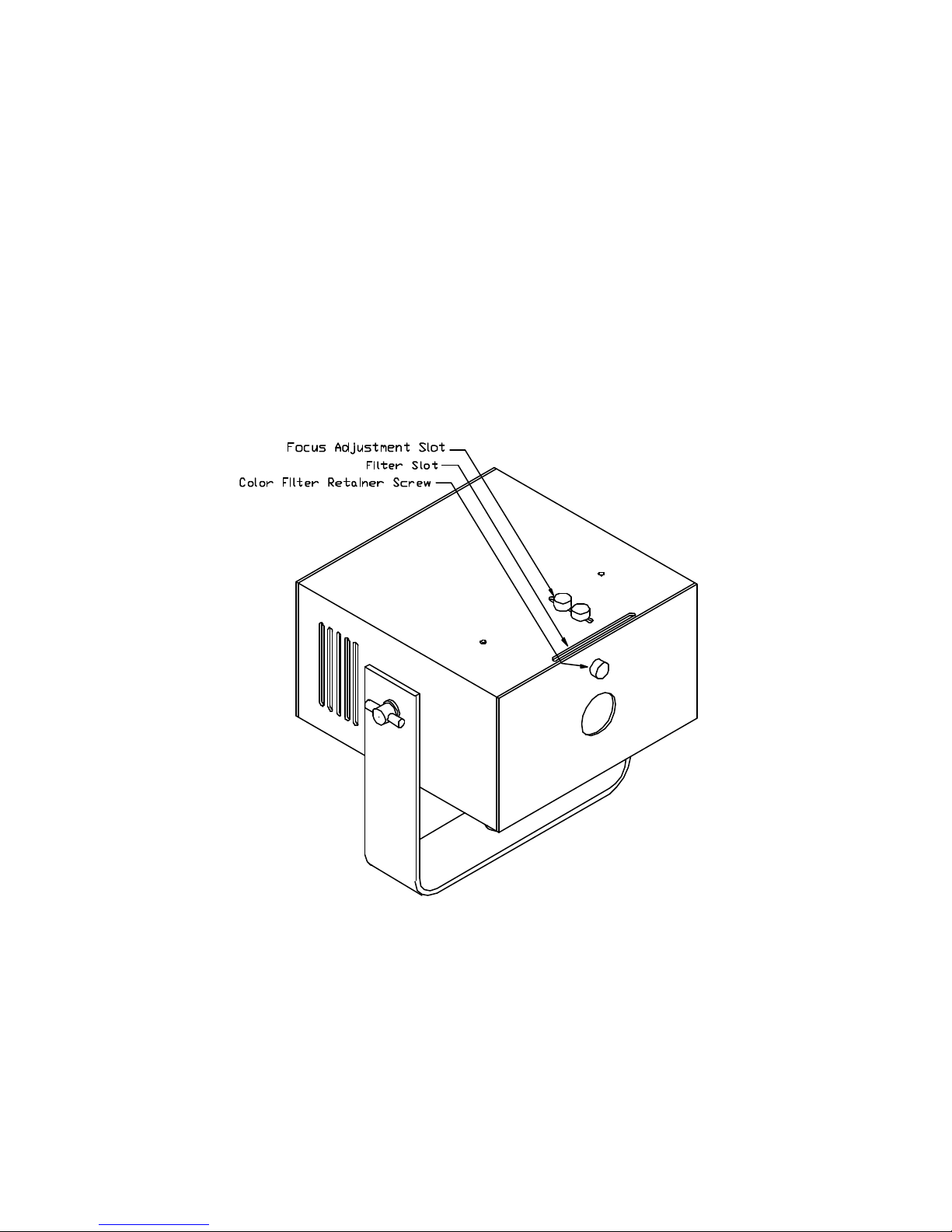
Focus Adjustment
The effect focus can be varied by moving the projection lens. This may be accomplished without opening the
unit case. Two small thumb screws on the upper or lower surface of the unit secure the lens mount. Loosen
both screws slightly, (but do not remove either screw) and use one of them as a handle to slide the lens mount
forward or back until the desired focus is achieved, then tighten both thumb screws securely.
Filter or Gel Installation
A slot for a color filter is provided at the front of the Firelight. Due to the high light output from the fixture,
only glass or dichroic color filters are recommended. Typical gel filters will tend to bleach or burn quickly due
to the high light output from the fixture, and would require frequent replacement. Color filters should be cut to
two inches by two inches, or 50mm square in size, and be no thicker than 1/16 inch, or 1.5mm. A
thumbscrew at the front of the unit retains the filter. Both color filters and shaped apertures may be used to
change the general character and appearance of the projected display.
To install or change a filter, disconnect power to the unit, remove the thumbscrew next to the output port, and
slide the filter into the slot in the case top or bottom nearest the thumbscrew. The filter should be pushed into
the slot until it stops, or at least until the edge of the filter or mount is clear of the thumbscrew hole. Reinsert
the thumbscrew and gently tighten it to retain the filter. If it is possible to invert the Firelight unit when
installing a filter, the filter can be simply dropped in or out of the slot after removing the thumbscrew. Be sure
to replace the thumbscrew before turning the Firelight right side up to hold the filter in place. Reconnect
power, then aim and focus the unit for normal operation.

Manual Effect Adjustments
Manual controls for effect intensity, color, motor speed, and motor direction are accessible at the rear of the
unit. Note that some or all of the manual trimmer controls may be inoperative when the fixture is operated in
DMX control mode. The selector switches for motor direction will operate as described in either manual or
DMX mode.
The LED intensity and effect motor speed controls are multi-turn potentiometers. These controls can be
adjusted using a small slot-blade screwdriver without opening the unit case. Rotating the controls clockwise
increases the setting, counterclockwise adjustment will decrease the setting. The controls are very precise,
and several turns may be required to produce a significant change. The controls do not stop or tighten at the
end of their adjustment range, but will continue to spin without causing any additional change at minimum or
maximum settings.
Changing Intensity
The fixture electronics have provisions for controlling two LED emitters, which are typically red and amber.
For each installed emitter, the intensity is adjusted by increasing or decreasing the setting of the matching
trimmer. The balance of color between two mismatched emitters, and the overall intensity of the fixture may
be adjusted to the users requirements by using these controls as necessary. The LED intensity controls are
non-functional in any DMX mode.
Changing Motor Speed
The two motor speed controls are used to adjust the rate of motion in the output pattern. The adjustment
ranges from slow enough to be barely perceptible, to very rapid and turbulent. For the most natural
appearance, both controls should be set from 5 to 7 turns from minimum. Higher or lower settings may be
used depending upon the display requirements. It is normal for the noise level from the effect motors to
increase at higher speed settings, but the motors will not be damaged by prolonged operation even at
maximum speed settings. Motor speed controls are non-functional in 3 or 4 channel DMX mode
Changing Motor Direction
Two switches control the direction of the two effect motors. Each switch controls one of the motors. The
switches can be set using a small slot-blade screwdriver or probe without opening the unit case. The
switches are accessible between the LED Intensity and Motor Speed controls on the rear panel of the fixture.
The switches are recessed to prevent accidental motor direction changes. Motor direction can be changed by
using a small screwdriver or probe to gently engage the switches, and move the switch toggle or rocker.
Avoid applying excessive force to the switches. Motor direction switches operate in all modes.
The motion of the projected effect can be significantly altered by changing the direction that the pattern
wheels rotate. Firelight units are shipped with both motors turning in opposite directions. Due to the
arrangement of the wheels, this produces an effect with either up or down motion, depending on the fixture
orientation. Upward motion produces the most realistic flame appearance, especially when the motors are set
at nearly equal speeds. Changing the direction of one motor will alter the pattern so that the effect motion
will be both upward or downward. If the resulting animation is not in the desired direction, i.e. up when you
want down, then changing the direction of both motors will correct the pattern motion. To obtain more
swirling, or interaction in the effect, one of the motors should be operated at a slightly faster or slower speed
than the other.

Dimming
The Firelight FL-BBlaze fixtures should not be operated from dimmed AC lighting circuits due to the voltage
adaptability of the “Universal Voltage” DC power supplies provided, as these units will attempt to
compensate for any variation in the input voltage. The unit should not be dimmed by attempting to vary the
DC power supply voltage either. If dimming is required in any application, the fixture should be dimmed using
the DMX control functions as intended.
LED Emitter Lifetime
The LED light sources used in the Firelight FL-BBlaze fixture should operate for tens of thousands of hours,
or several years of daily operation without requiring replacement. A decrease of from 25 to 30 percent in
intensity can be expected after approximately 50,000 hours of operation. If the unit is mounted close to high
wattage fixtures, or otherwise operated in hot environments, the output of the LED emitters may decrease
more rapidly, but should not require replacement over the lifetime of the fixture.
In the event that a fixture appears to be operating at reduced output, especially if the selected output color
changes abruptly, it is possible that an LED emitter has failed prematurely. Evaluation the fixture for
improper control settings, dust or dirt contamination, or other routine problems. The unit may be returned for
service if an LED emitter failure is confirmed.
Maintenance
The only maintenance recommended is a periodic cleaning to remove dust accumulation from the fixture.
The proper cleaning interval is determined by the amount of dust in the environment, which may be
established by inspecting the unit at regular intervals over the first 12 months of operation.
The FL-BBlaze fixture is fan cooled, and there is no clear path to draw air or dust through the optical section
of the fixture. Dust will eventually build up outside and inside the fixture over time. Heavy accumulations of
dust will reduce the fixture output, and may reduce the airflow through the unit, resulting in increased
temperatures and reduced LED lifetimes.
Periodic cleaning with compressed air or bottled gas will remove most light dust contamination. Heavy dust
contamination may require removal of the fixture outer cover for more thorough cleaning of the interior and
effect optics using compressed air, aided by a soft dry brush or tissue paper. Severe contamination by dust in
combination with oil, and fog or smoke fluid residue may require the use of a cleaning cloth or tissue
dampened with water, or a water based cleaner to thoroughly remove dirt from the fixtures exterior, interior,
and optical surfaces. Proper cleaning will generally restore the fixture to original performance.
The two DC effect drive gearmotors installed in the unit are sealed and permanently lubricated, and should
not require maintenance over the lifetime of the fixture. Some minor leakage of oil from the motors may be
expected over time, but this is not an indication of motor failure, and is objectionable mainly because of the
dust it tends to capture inside the fixture. After prolonged operation, typically 15 to 20 thousand hours, the
gearmotors may fail to operate due to brush wear or contamination. Regular operation of the effect motors at
high speed, or temporarily running an inoperative motor at a high speed setting will help to clear off any brush
contamination, extending the fixture lifetime or restoring an intermittent motor to normal operation. Worn
out brushes will eventually require the replacement of the effect drive motors.
Although the fixture is designed for continuous operation, for the longest motor lifetimes, the fixture should be
operated only when an active display is required, and should be powered off when not needed.

Troubleshooting
Problem Probable Cause
Fixture completely inoperative: No AC line voltage to power supply
No “Power” indicator Power supply input cord unseated at supply
Power supply output cord unseated at fixture
Power supply or cable defective
Good “Power” indicator, No DMX data applied
No DMX “Sync” indicator Bad DMX cable or connection
Good “Power” indicator, DMX address settings incorrect (DMX Mode)
Good DMX “Sync” indicator DMX control settings at minimum (DMX Mode)
Manual control settings at minimum (Manual Mode)
Blinking DMX “Sync” indicator DMX address out of normal range
Erratic DMX “Sync” indicator Bad DMX cable or connection
Effect motors operate normally, No DMX data applied (1 or 2 Channel mode)
but no light output DMX address settings incorrect
Manual control settings at minimum (Manual Mode)
Defective LED emitters or LED drivers
LED Emitters operate normally, Motor speed settings at minimum (1-2 Ch. / Manual Mode)
but no effect motion or animation Motor direction switches set at mid-position
Defective effect motor or motor driver
Fixture partially illuminates the normal Fixture output blocked or occluded
display area Manual intensity setting at minimum (Manual Mode)
DMX data for inactive area at minimum (4 Ch. Mode)
Defective LED emitters or LED drivers
Fixture buzz or excessive noise Some hum and quiet buzzing sound is normal
Foreign object lodged in fan
Worn or defective effect motor or fan
Effect motor operating at maximum speed
Weak or uneven output pattern Fixture focus set incorrectly
Fixture optics dirty or damaged
LED emitter or lens damaged
No pattern motion, or directional motion. One or both motor speeds set at minimum
Fixture effect wheel loose or jammed
Defective effect drive motor
Fixture is excessively hot High ambient temperature at fixture location
Ventilation slots blocked or obstructed by dust
Cooling fan Inoperative

PRECISION PROJECTION SYSTEMS, INCORPORATED
17508 STUDEBAKER ROAD, CERRITOS, CA.90703
562 865-8552 TELEPHONE 562 924-7133 FAX
LIGHT
MODEL FL-B
SPECIFICATIONS
Housing .060 Aluminum
Finish: Black Anodized / White Powder Coat
Yoke: 1.5" x .125" Aluminum,
.5" Diameter Mounting Hole
Weight: FL-B Unit, 2 lbs (.92 Kg)
Transformer .4 lbs. (.18 Kg)
Mounting Any Orientation
R
MECHANICAL: ELECTRICAL:
OPTICAL:
Input Voltage: FL-B Unit: 9-24 Volts DC, 30 watts
Transformer: 100 - 240 VAC 50/60 Hz.
UL listed Class 2 power supply,
Universal input voltage
Controls: Manual focus and effect direction
Manual or DMX speed and intensity
DMX 5 pin XLR, isolated input and output
OPTIONS AND ACCESSORIES:
Emitters Dual 10 Watt White LED
Lumen Maint. 25,000 hours at 70% minimum
Color Temp 6300 Kelvin "Cool White"
Dispersion 53 degrees typical, soft edge
Gel / Filter 2 x 2" or 50 x 50mm square,
1/16" or 1.5mm max thickness
glass or dichroic material required
IP65 Housing Call for specifications and pricing
Custom Color Available with quantity orders
Mirror Acc. Redirects fixture output.
C Clamp Black "Mega Clamp" for mounting
Double Lens For extra wide dispersion
Output Modes PWM or Linear output available
FIRE
This manual suits for next models
1
Table of contents


