Firestone AIRIDE 2639 User manual
INSTALLATION INSTRUCTIONS
2639
10-23
firestoneairide.com

1 firestoneairide.com
IMPORTANT
PLEASE DON’T HURT YOURSELF, THE KIT, OR YOUR VEHICLE. TAKE A MINUTE TO READ THIS IMPORTANT INFORMATION.
SAFE INSTALLATION
Please take all safety precautions during installation. A hydraulic jack can fail, and if that happens, you can be
seriously hurt, or worse, if you are relying on it to hold up the vehicle. If you use a hydraulic jack, secure jack
stands in the appropriate locations and chock any tires still touching the ground.
Wear safety glasses or goggles.Your eyes may be lower than some parts and pieces, and you don’t want to losean eye.
Remove the possibility of any electrical issues by disconnecting the negative battery cable.
VEHICLE GVWR
NEVER exceed the maximum load recommended by the vehicle manufacturer (GVWR).The GVWR can be found
in your vehicle’s owner’s manual or on the data plate on the driver’s side door. Consult your local dealership for
additional GVWR specifications.
PRESSURE TO LOAD
Be sure to review the load limits noted in the Air Spring Kit Installation Instructions (sold separately).
APPROPRIATE AIR PRESSURE
For best ride, use only enough air pressure in the Air Springs to level the vehicle when viewed from the
side (front to rear).This will vary, depending on the load, location of the load, condition of the existing
suspension, and personal preference.
ONCE INSTALLED SUCCESSFULLY, FOLLOW THE PRESSURE REQUIREMENTS FOR THE AIR SPRINGS.
FOR FIRESTONE, GENERALLY:
305 1005 1505
COIL-RITE RIDE-RITE RED LABEL
2639 Installation Instructions 2
PARTS
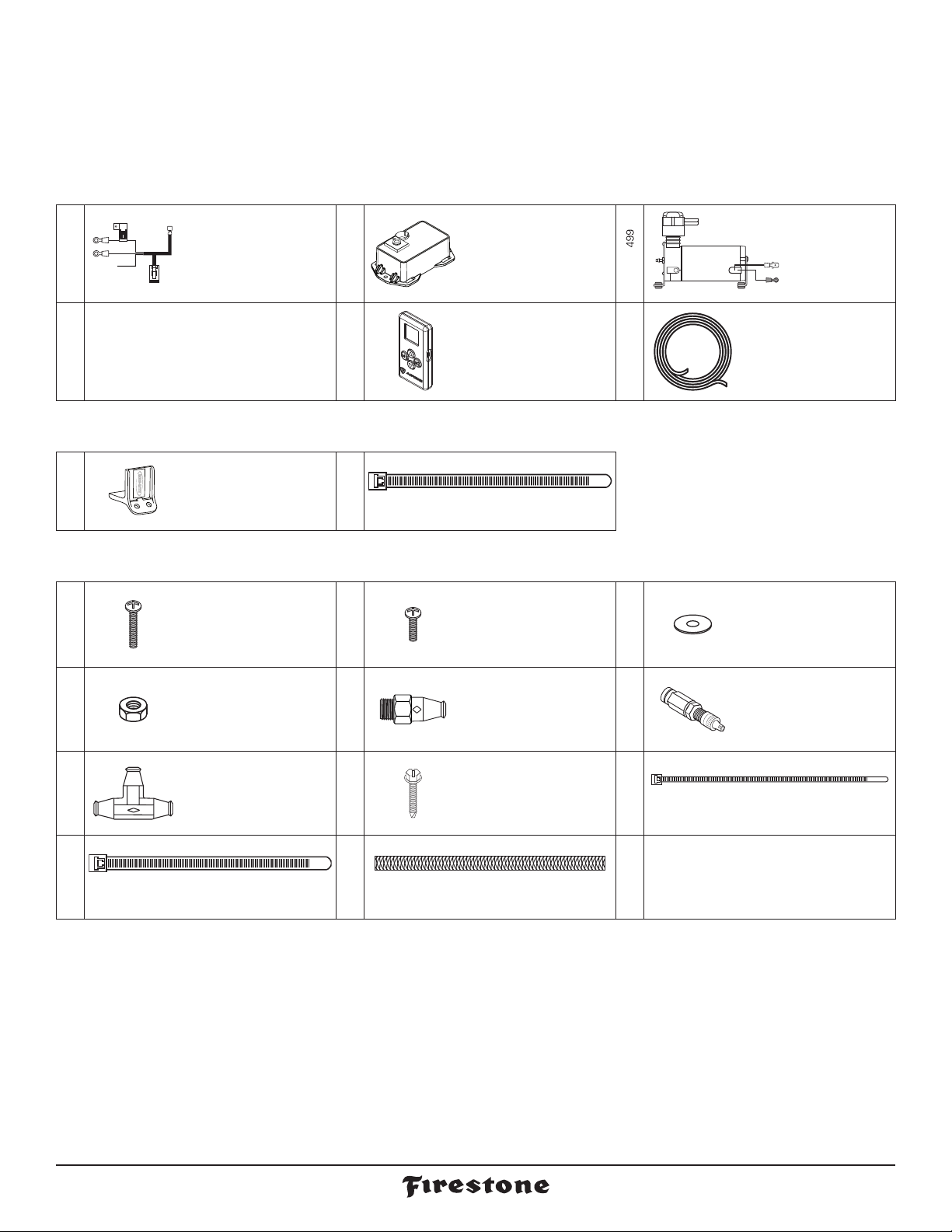
Compare the parts below to your kit. Assure you have all pieces, and organize them for an easier installation.
MAIN KIT CONTENTS
PT # 9534
x 1 WIRE HARNESS
PT # 9535
x 1 ECU
PT # 9PT # 9414
x 1 AIR LINE TUBE
(18 FEET)
A24-760-7560 INFLATION VALVE BRACKET KIT
PT # 9483
x 1
NO-DRILL
INFLATION VALVE
BRACKET
PT # 9488
x 2 LARGE NYLON TIE
A21-760-2610 HARDWARE PACK
PT # 3087
x 4 10-32 x 1"
MACHINE SCREW
PT # 3093
x 2 10-32 x 3/4"
MACHINE SCREW
PT # 3086
x 10 #10 FLAT WASHER
PT # 3088
x 6 10-32 NYLOCK NUT
PT # 3055
x 1
1/8 NPT PUSH-
TO-CONNECT
STRAIGHT FITTING
PT # 3032
x 1
INFLATION VALVE
AND VALVE CAP
ASSEMBLY
PT # 3025
x 3 1/4" PUSH-TO-
CONNECT TEE
PT # 3421
x 1
10-16 x 3/4"
SELF-TAPPING
SCREW
PT # 9036
x 8 RED NYLON TIE
PT # 9488
PT # 0899
x 2 LARGE NYLON TIE x 2 THERMAL SLEEVE
x 1 AIR COMPRESSOR
KIT
PT # 9968
x 1 AIR COMMAND
SINGLE REMOTE

firestoneairide.com3
CONTENTS AND OVERVIEW
PAGE 4PLANNING THE
INSTALL
PAGE 5PREPARE THE AIR
COMPRESSOR
PAGE 6DRILL HOLES FOR
AIR COMPRESSOR
AND ECU
PAGE 7INSTALL THE
AIR COMPRESSOR
AND ECU
PAGE 8INSTALL THE
WIRE HARNESS
PAGE 9INSTALL THE
AIR LINE TUBES
PAGE 10 OPTIONAL INFLATION
VALVE INSTALLATION
PAGE 11 INSTALL THE
AIR FILTER AND
CLEAN UP
PAGE 12 CONNECTING
TO THE APP
9535 ECU
AIR SPRINGS
(sold separately)
AIR LINE TUBE
AIR LINE TUBE
AIR LINE TUBE
AIR LINE TUBE
INFLATION
VALVE
INFLATION
VALVE NUT
& WASHER
AIR LINE TUBE
1/4” PUSH-TO-
CONNECT TEE
1/4” PUSH-TO-
CONNECT TEE
OPTIONAL MANUAL
INFLATION VALVE
LEFT AIR SPRING
(when facing forward)
See step 6
for details.
RIGHT AIR SPRING
(when facing forward)
* As a water/debris
trap. See page 4.
Create
loop in Air
Tubing.
AIR FITTING
AIR LINE TUBE
AIR FILTER
20 AMP FUSE
RED (+)
RED/WHITE
ECU
CONNECTOR
(COMPRESSOR +)
BATTERY (+)
YELLOW
+12V IGN
9534 WIRE
HARNESS
BLACK (-)
BATTERY (-)
1/4” PUSH-TO-
CONNECT TEE
NOTE:The yellow wire is not
used, but should be protected
from the environment.
* As a water/debris
trap. See page 4.
Create
loop in Air
Tubing.
9499 AIR
COMPRESSOR
PAGE 13 SINGLE REMOTE
PAGE 15 TEST THE SYSTEM
PAGE 16 FIX AN AIR LEAK
AIR COMMAND
QUICKSTART GUIDE
™3032
3025
3025
3025

2639 Installation Instructions 4
PLANNING THE INSTALL
THESE PLANNING STEPS WILL HELP YOU SAVE TIME AND WILL MAKE THE INSTALLATION EASIER.
DETERMINE THE MOUNTING LOCATION FOR THE AIR COMPRESSOR
- Provides ample air flow and is protected from airborne debris and moisture.
If using the optional Firestone Air Accessory Mounting Kit, consider the
guidelines above, and follow the kit’s instructions.
DETERMINE THE MOUNTING LOCATION FOR THE ECU
Mount close enough to the Air Compressor to allow Wire Harness
connections to reach.
- Allow room for Air Tubing to connect to the Air Fitting on the ECU.
- Allow room for the Air Tubing to run without sharp curves or bends.
Using supplied fasteners shown in Step 3 is recommended. If no other mounting option is available,
see the sidebar on Step 2 for using the Large Nylon Ties.
Select a location that is solid and secure on the body or frame of the vehicle, away from any moving parts,
electrical or any other lines.
PLAN INSTALLATION ROUTES FOR WIRING AND AIR LINES
- Use supplied Thermal Sleeves on Air Tubing when routing near heat sources.
- Use supplied Nylon Ties to secure Air Tubing and Wire Harness to the vehicle.
- Make a loop in the Air Tubing where shown.This creates a water/debris trap that protects the Air Compressor.
- Measure twice, cut once!
TAPE ALL ELECTRICAL CONNECTIONS
- Use electrical tape to appropriately secure and protect all electrical connections.
USING PUSH-TO-CONNECT FITTINGS FOR AIR LINES
Your kit includes Push-to-Connect fittings to connect the Air Tubing to hardware.
Use the instructions below when using the Air Tubing.
1Insert end of Air
Tubing into
Air Fitting. 2Push Air Tubing
into Air Fitting as
far as possible. 3Gently pull on
the Air Tubing
to check for a
secure fit.
4To remove, push
down collar and
gently pull Air
Tubing away.
Removal Tip: Use a 1/4 , 5/16
or 6mm open-ended wrench
to push the collar down.
- Allow room for the 4-pin ECU connector to connect to the ECU.
- Mount close enough to the ECU to allow Wire Harness connections to reach.
- Make sure the Wire Harness and Air Tubing are not exposed to sharp metal edges that can damage them.

firestoneairide.com5
PREPARE THE AIR COMPRESSOR
1
NOTE: Air Compressorcan be mounted facing any direction.
1Install 1/8 NPT Push-to-Connect
Straight Fitting on the Check Valve.
3055 1/8 NPT PUSH-TO-CONNECT
STRAIGHT FITTING
Tighten to engage two threads
of thread lock.
PRE-INSTALLED
CHECK VALVE
9499 AIR COMPRESSOR
2639 Installation Instructions 6
9535 ECU
9535 ECU
If there is no other
mounting option,
use two Large Nylon
Ties to secure ECU to the
location determined in
planning the install
section. Route the Nylon
Ties under the ECU and
around the mounting
location.
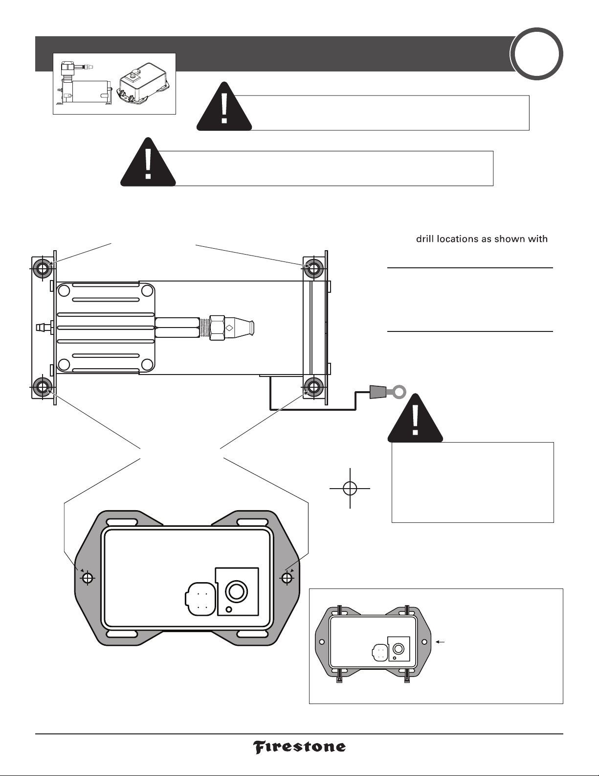
DRILL HOLES FOR AIR COMPRESSOR AND ECU 2
7/32”
IF YOU ARE USING THE OPTIONAL FIRESTONE AIR ACCESSORY MOUNTING
KIT, SKIP THIS STEP AND REFER TO THE MOUNTING KIT’S INSTRUCTIONS.
CHECK SURROUNDING AREA AND BACK SIDE OF MOUNTING
LOCATION TO AVOID DRILLING INTO EXISTING LINES OR WIRING.
1Using the Air Compressor
and ECU as templates, mark
a punch or marking tool.
2Mark Air Compressor
ground wire fastening
location within reach of the
ground wire ring terminal.
3Drill 7/32" diameter holes.
Remove any burrs and
debris from drill holes.
ASSURE THAT YOU INSTALL THE
AIR COMPRESSOR AND ECU CLOSE
ENOUGH SO THE CONNECTORS ON
THE WIRE HARNESS WILL REACH
THEM BOTH.
OPTIONAL ECU MOUNTING
9499 AIR COMPRESSOR
BLACK
GROUND
WIRE
Drill within reach of the ground wire
ring terminal on body or frame of
vehicle. AIR ACCESSORY MOUNTING
KIT CANNOT BE USED AS A
GROUNDING LOCATION FOR THE AIR
COMPRESSOR.
Use as template to
mark drill locations.
Use as template to
mark drill locations.

firestoneairide.com7
3093 10-32 x 3/4” MACHINE SCREW
3088 10-32 NYLOCK NUT
ECU
3088 10-32 NYLOCK NUT
3086 #10 FLAT WASHER (or optional Firestone
Air Accessory
Mounting Kit).
BODY OR FRAME
OF VEHICLE
INSTALL THE AIR COMPRESSOR AND ECU
3
x 10x 2x 4 x 6
DO NOT OVER TIGHTEN MOUNTING BOLTS AND NUTS ON THE AIR COMPRESSOR.
TOO MUCH TORQUE CAN CRUSH THE BRASS INSERTS AND RUBBER ISOLATORS.
1Mount the Air Compressor
to the drill hole location
using the suppliedfasteners.
DO NOT OVERTIGHTEN.
2Mount the ECU to the drill
hole location using the
supplied fasteners. 3Mount the black ground wire
ring terminal using the sup-
plied fasteners. Assure that
the ring terminal makes
a solid contact with bare
metal for a proper ground.
9499 AIR COMPRESSOR
3086 #10 FLAT WASHER
3087 10-32 x 1” MACHINE SCREW
3088 10-32
3086 #10 FLAT
BLACK
GROUND
WIRE
Body of vehicle
(or optional Firestone
Air Accessory
Mounting Kit
– Part #2588)
3088 10-32 NYLOCK NUT
3086 #10 FLAT WASHER
10-16 x 3/4”
SELF-TAPPING SCREW
NOTE: You may want to
combine other grounds
to this mounting location.
BODY OR FRAME
OF VEHICLE
Air Accessory Mounting
Kit cannot be used
as a grounding
location for the
Air Compressor.
NYLOCK NUT
WASHER
2639 Installation Instructions 8
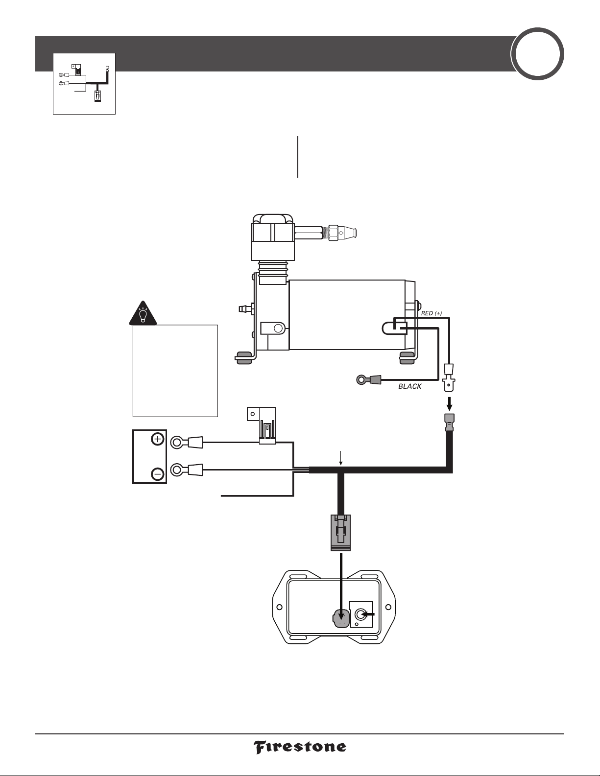
INSTALL THE WIRE HARNESS 4
1Route the Wire Harness in the most
protected manner possible, and securely
make all connections as shown. 2The yellow wire is not used. Wrap or wire
nut it to protect it from the environment.
12V
BATTERY
9535 ECU
20 AMP FUSE
RED (+)
RED/WHITE
ECU
CONNECTOR
(COMPRESSOR +)
BATTERY (+)
YELLOW
+12V IGN
9534 WIRE
HARNESS
BLACK (-)
BATTERY (-)
NOTE:The yellow wire is not
used, but should be protected
from the environment.
Why ground the Wire
Harness to the battery?
The ECU needs a good,
clean ground for opti-
mal accuracy. The Air
Compressor can ground
to the frame, but the
ECU cannot.
9499 AIR COMPRESSOR

firestoneairide.com9
3055 1/8 NPT PUSH-TO-CONNECT
STRAIGHT FITTING
9535 ECU
AIR SPRINGS
(sold separately)
AIR LINE TUBE
AIR LINE TUBE
AIR LINE TUBE
1/4” PUSH-TO-
CONNECT TEE
1/4” PUSH-TO-
CONNECT TEE
LEFT AIR SPRING
(when facing forward)
RIGHT AIR SPRING
(when facing forward)
* As a water/debris
trap. See page 4.
Create
loop in Air
Tubing.
INSTALL AIR LINE TUBES
5
DO Make sure the cut is as square as possible.
Use a tube cutter or very sharp utility knife. DON’T Fold or kink the Air Tubing.
Cut the Air Tubing at an angle.
Use pliers, scissors, snips,
saws, or side cutters.
Square cut
90˚
AIR TUBING AIR TUBING AIR TUBING AIR TUBING
PROPER AND IMPROPER CUTS IN THE AIR TUBING
EXHAUST ALL AIR FROM THE SYSTEM PRIOR
TO RELEASING AIR TUBES FROM AIR FITTINGS. 5
PSI
1Route the Air Tubing from
1/8NPT Push-to-Connect
Straight Fitting on the top of
theAir Compressor to the
first 1/4" Push-to-Connect Tee.
2From the 1/4" Push-to-
Connect Tee, route Air
Tubing to the ECU, as shown.
3Route Air Tubing from
each Air Spring and connect
to a 1/4" Push-to-Connect
Tee, as shown.
4Route Air Tubing to
connect the two 1/4" Push-
to-Connect Tees, as shown.
x 2
9499 AIR
COMPRESSOR
3025
3025

2639 Installation Instructions 10
INFLATION
VALVE
1/4” PUSH-TO-
CONNECT TEE
1/4” PUSH-TO-
CONNECT TEE
To air compressor
To air springs
To ECU
1/4” PUSH-TO-
CONNECT TEE
RUN AIR LINE TO OPTIONAL INFLATION VALVE 7
1Secure the Air Inflation
Valve Bracket to a pro-
tected, secure location.
PROCEEDTO STEP 3.
2Select aprotected location
to install the Inflation Valve,
such as the bumper or the
body of the vehicle.
Drill a 5/16" hole for
Inflation Valve install
location.
3Install Inflation Valve
Assembly as shown.
OPTIONAL INFLATION VALVE INSTALL 6
x 2 x 2
LARGE
NYLON TIES
Inflation Valve
install locations.
BUMPER
INFLATION
VALVE
EXAMPLE
INFLATION VALVE
AIR LINE TUBE
VALVE CAP
INFLATION
VALVE NUT
5/16” - 16 FLAT WASHER
Vehicle body,
bumper or
Inflation Valve
Bracket.
IF USING THE OPTIONAL NO-DRILL INFLATION VALVE BRACKET, CHOOSE OPTION 1. IF DRILLING,
CHOOSE OPTION 2. INFLATION VALVE MUST BE ACCESSIBLE BY AN AIR CHUCK.
5/16”
1Run Air Tubing from the
location of the installed
Inflation Valve in Step 6
to the Air Tubing that
connects the two installed
1/4" Push-to-Connect Tees.
2Cut the piece of Air Tubing
that connects the two
installed 1/4" Push-to-
Connect Tees.
3Install the Air Tubing into the
1/4" Push-to-Connect Tee,
as shown.
4Install the Air Tubing
into the Inflation Valve,
as shown.
3025
3025
3025
3032
3032

firestoneairide.com11
INSTALLING THE AIR FILTER
8
AIR LINE TUBE
FROM AIR COMPRESSOR KIT
AIR FILTER
Create
loop in Air
Tubing.
FILTER LIFE WILL VARY BASED ON ENVIRONMENTAL CONDITIONS.
PROTECT THE AIR COMPRESSOR BY CHANGING THE AIR FILTER
MORE FREQUENTLY IN DUSTY CONDITIONS.
CLEAN UP INSTALLATION
9
1Clean up the installation using
supplied Nylon Ties, and return
all factory parts and materials
to operative state.
USING SUPPLIED NYLON TIES, SECURE ALL
WIRING AND AIR LINE TUBE IN A MANNER
THAT DOES NOT OBSTRUCT MOVING PARTS
OR IN ANY WAY THAT AFFECTS YOUR ABILITY
TO SAFELY OPERATE THE VEHICLE.
1Fully secure the Air Filter
Barb into the Air Tubing
from the Air Compressor Kit. 2Press Air Tubing onto the
Barb on the Air Compressor
Air Fitting until fully seated.
Assure you create a loop in
the Air Tubing, as shown,
when securing it to the
vehicle.
3Periodically check the Air
Filter during operation.
When the Air Filter is dirty
and needs to be replaced,
contact an Authorized
Firestone dealer to
purchase a new one.
SECURE THE AIR FILTER IN A LOCATION THAT
PROTECTS IT FROM MOISTURE AND DEBRIS,
AND IS ABOVE THE LOOP INTHE AIR LINE TUBE.
9499 AIR
2639 Installation Instructions 12
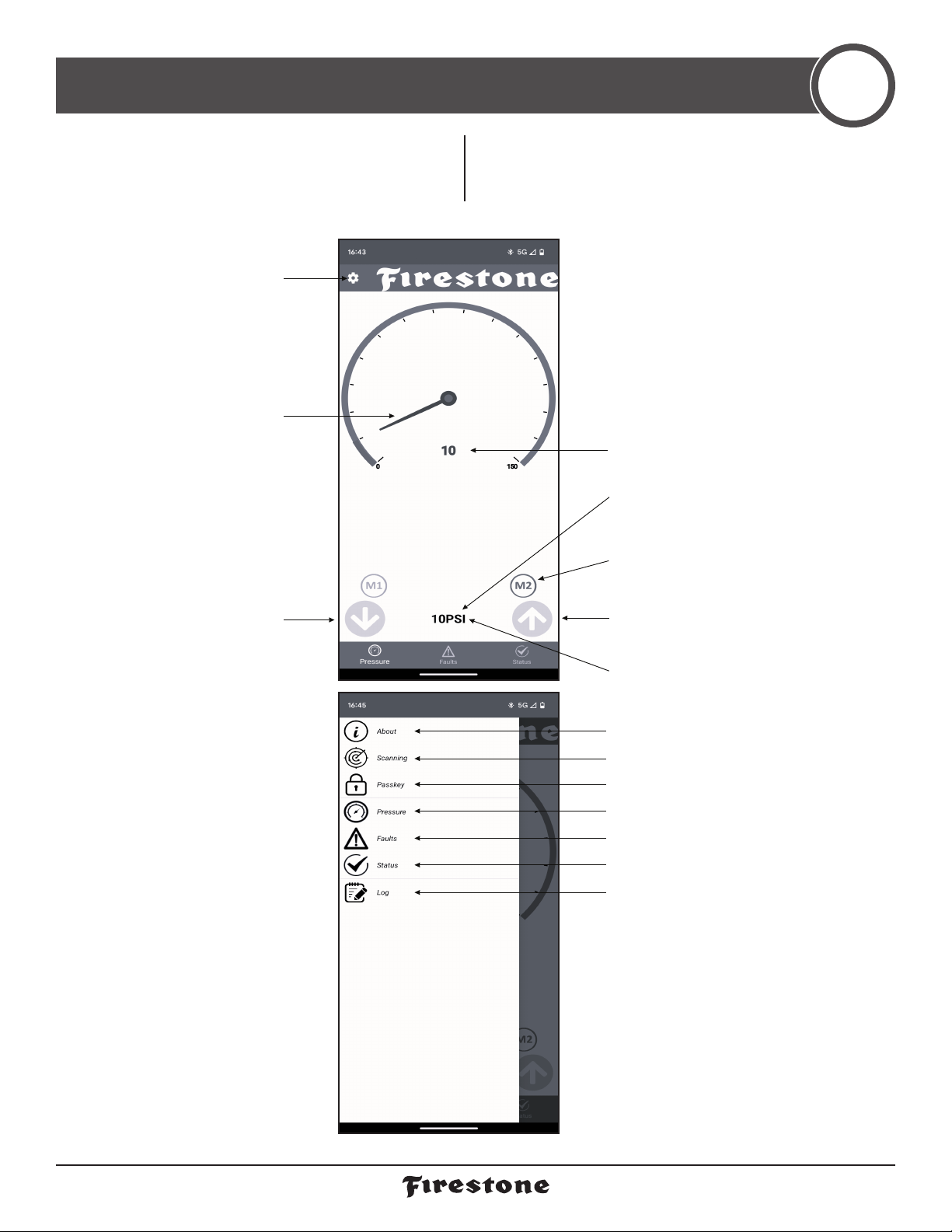
CONNECTING TO THE APP 10
1Download and install the Firestone Air
Command app on a compatible iPhone
or Android device. 2Open the app. Once the app has
established a Bluetooth connection on
startup, it will automatically link to the ECU.
SETTINGS
APP AND ECU INFORMATION
CONNECTION SCREEN
MAIN APP SCREEN
SHOW FAULTS SCREEN*
SHOW SYSTEM STATUS SCREEN
CHANGE PASSKEY User set or default (1234).
SHOW LOG SCREEN FOR TROUBLESHOOTING
* Any faults will include
troubleshooting instructions
UNITS
MEMORY BUTTONS
To set memory, hold down target
pressure, then press M1 or M2.
INCREASE PRESSURE
DECREASE PRESSURE
NEEDLE AND BAR
Shows actual pressure. Can be
used to change pressure.
MAIN APP SCREEN
SETTINGS
TARGET PRESSURE
Set by user.
ACTUAL PRESSURE
-
firestoneairide.com
13
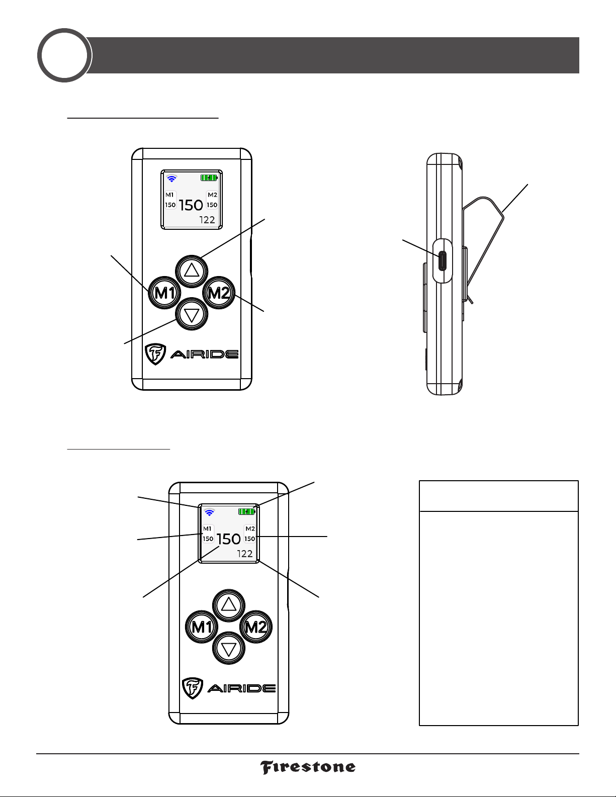
AIR COMMAND SINGLE REMOTE QUICKSTART GUIDE
11
Increase
Pressure/
Move Up
Set or Select
Memory 2/
Move Right
Visor Clip
USB-C
Charging
Port
Set or Select
Memory 1/
Move Left
Decrease
Pressure/
Move Down/
Screen Exit
Remaining
Battery Level
Saved Pressure
for Memory 2
Set Pressure
Target
Wireless
Signal
Strength
Saved Pressure
for Memory 1
Current
Pressure
Reading
▪The Air Command App by
default requires users to input
the controllers passcode before
Bluetooth allows connection.
▪The Air Command Remote
will connect automatically as
long as the passcode on the
remote matches the controllers.
▪The default passcode is 1234.
▪Double check the passcode
from the app if using both to
connect to the controller.
▪The next page shows how to
access the passcode menu and
change it on the remote.
CONNECTION TO AIR COMMAND
CONTROLLER:
1FUNCTIONS OF REMOTE BUTTONS
2HOME SCREEN LAYOUT
™

AIR COMMAND SINGLE REMOTE QUICKSTART GUIDE
2639 Installation Instructions 14
Brightness - Adjust the intensity of the
backlit screen.
Timeout - Adjust how long the remote will
stay idle before turning off.
PSI/BAR - Select pressure unit of measure.
PSI - Imperial BAR - Metric
Passcode - Use all 4 buttons to
navigate and adjust the passcode
selection.
*If also using the app the pass-
codes entered must both be the
same. Default passcode is 1234.
Not Connected! - If this warning
remains more than 30 seconds
after waking up the remote does
not detect an active ECU. It
could be caused by a wiring
issue, the ECU not getting power,
or an incorrect passcode.
When the remote is off,
press any button to turn
on the remote.
Hold the up and down arrows
at the same time to access the
remote settings screen.
Hold down M1 and M2 to
access the passcode
entry screen.
3ACCESSIBILITY
™
firestoneairide.com
15
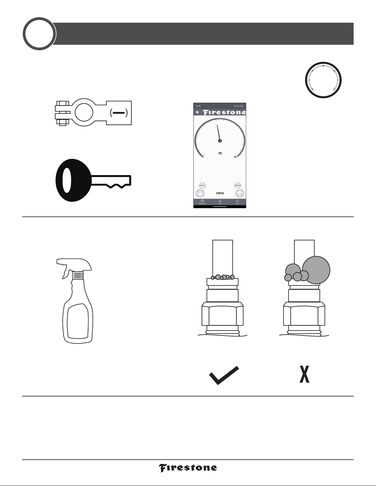
TEST THE SYSTEM
12
With the Air Command™App and yourairsprings installed, you are ready to test the system.
NO LEAKS?
Congratulations!You’re riding right with the push of a
button! Remember to review the Operating Instructions.
LEAK?
Bummer. Continue to step 13 to fix the leak.
1Reattach the negative
battery cable.
2Turn on your vehicle’s ignition.
4Spray fittings with
soap and water mixture
or glass cleaner. 5Observe bubbles.
3Use the Air Command App or
Single Remote to inflate the
Air Springs to 70 PSI.
See Step 10 or 11 for details.
70
PSI
WATER
+
SOAP
SMALL SOAP BUBBLES
THAT DO NOT EXPAND
SOAP BUBBLES
THAT EXPAND
™
2639 Installation Instructions 16
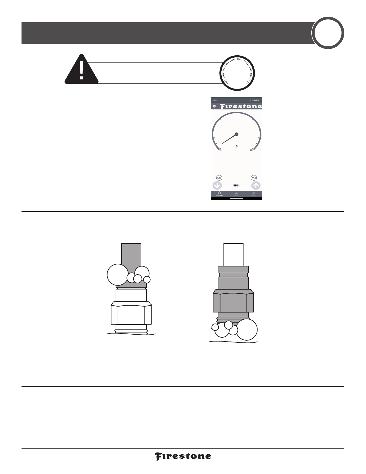
FIX AN AIR LEAK 13
STILL HAVE A LEAK?
Refer to theTroubleshooting section of the Instruction Manual. If the leak persists, or if there is an issue with
a leaking part, email us at [email protected]. If emailing, please include photos to help us better diagnose and
understand any problems you may be experiencing.
LEAK AT AIR TUBING
AND AIR FITTING
LEAK AT BASE OF AIR FITTING
Release Air Tubing (see page 4).
Review proper cuts and proce-
dures in step 5. Repeat step 5.
Tighten Air Fitting one turn
or until leak stops.
1Use the Air Command App or
Single Remote to deflate the
Air Springs to 5 PSI.
See Step 10 or 11 for details.
EXHAUST ALL AIR FROM THE SYSTEM PRIOR
TO RELEASING AIR TUBES FROM AIR FITTINGS. 5
PSI
™

17 firestoneairide.com
NOTES

2639 Installation Instructions 18

2639
10-23
BEFORE YOU DRIVE, CONFIRM THE FOLLOWING:
Secure all AirTubing and wiring.
The system passes the leak test and holds air.
The Air Compressor ground ring terminal is contacting bare metal, and coated with silicone if possible.
The Wire Harness is grounded to the negative (-) battery terminal.The ECU needs a good, clean,
interference-free ground.
There is a loop in the AirTubing as shown to prevent water or debris from getting into the Air
Compressor head and damaging it.
Or, email us at rrtec[email protected]. If emailing, please include photos to help us better diagnose and
understand any problems you may be experiencing.
CONNECT WITH US @firestoneairide FirestoneAiride Firestone Airide
firestoneairide.com
Table of contents
Other Firestone Air Compressor manuals


Popular Air Compressor manuals by other brands

Atmos
Atmos PDK 33 Series Operation and Maintenance Handbook

Powerex
Powerex SES02 manual

Pulsar
Pulsar PCE6200 owner's manual

Euromate
Euromate B-KPS-24/165 Translation of the original instructions

Eaton Compressor
Eaton Compressor POLAR AIR PP05H080I1 user manual

Sullair
Sullair LS-25S Operator's manual and parts list


