Staging Considerations
You should set up and test your nodes indoors, on a bench or ta-
ble, before installing them. This will allow you to pre-congure
the nodes so that they are all on the same RF channel, etc. You
will use HotView Pro to congure the HotPort nodes and create
a small mesh network. Test the network settings you plan to use.
1. Check to see that all nodes are visible in HotView Pro. If not,
troubleshoot per directions in the HotView Reference Guide.
2. Set the Country Code for your country of operation.
3. Re-verify that all nodes are visible, and verify that dual-
radio nodes have both radios correctly meshed.
Warning: The staging antennas provided with Firetide outdoor
nodes are for temporary use only. They MUST be re-
placed with outdoor-rated antennas as soon as the
mesh is staged and operational. The staging anten-
nas are NOT waterproof and NOT moisture resistant. If
used outdoors, the antennas may fail.
Your CD has a copy of Firetide’s Accessory Guide. Contact your
Firetide Reseller for assistance in selecting and ordering outdoor
antennas suitable for your application(s).
•It is often easier to install all devices onto a pole, and then
attach the pole to the roof. In many cases, connecting the
devices to a pole already attached to the roof top can be dif-
cult and dangerous.
• A lightning surge suppressor must be used. Some antennas
include one. If not, install a lightning surge suppressor.
• Locate the HotPort close to the antenna; a short antenna
cable gives better performance than a longer one. Firetide
recommends antenna cables less than 3 meters.
Planning Your Installation
• The HotPort node and its antenna must both be grounded.
• Use non-vulcanized rubber weatherproong kits to weather-
proof connectors and antennas.
Preparing Earth Ground
The HotPort node must be properly connected to earth ground.
Failure to do so may result in equipment damage, injury, or
death. The product warranty does not cover damages resulting
in part or in whole from improper grounding. Consult your loca-
tion’s building and electrical codes regarding antennas and fol-
low them, or consult the National Electric Code (NEC).
• If connecting to a tower or pole, connect the base of the
tower pole directly to the building’s ground or to one or
more approved grounding rods using 10 AWG ground wire
and corrosion-resistant connectors.
• Connect the grounding cable to rain gutters only if the
rain gutter is connected to earth ground.
• Ground rods should be copper, 1.8 - 2.4 m (6 - 8 ft) long.
• Install all grounding components in straight lines. If bends
are unavoidable, do not make sharp turns.
• Earth-to-ground should not be more than 10 ohms.
Antenna Placement
Firetide recommends the use of antennas specically designed
for MIMO applications. While it is possible to select and mount
six individual antennas, determining correct placement and
spacing is difcult. Use an antenna engineered for best results
with MIMO.
Mounting the Universal Bracket
You can mount the enclosure to a wall, a light pole, or an ir-
regularly shaped pole. The universal mounting bracket has been
designed with multiple holes and slots to allow mounting with
bolts, straps, or other methods. Extra nuts and bolts are pro-
vided for this purpose; don’t be alarmed if you have leftover
fasteners when installation is complete.
Removing the Bracket
The bracket is shipping already attached to the HotPort node.
Begin by removing it. This is done by loosening the four Phillips
screws, two on each side. Next, slide the plate down, toward the
connector side of the HotPort node. This releases its tabs from
the node itself.
Wall Mounting
The Universal Mounting Bracket contains holes and slots to al-
low it to be mounted via U-bolts or straps. Use four screws (not
supplied) to attach the universal mounting bracket securely to
the wall using the four holes near the top and bottom of the
universal mounting bracket. Use appropriate anchors when at-
taching to masonry or other materials.
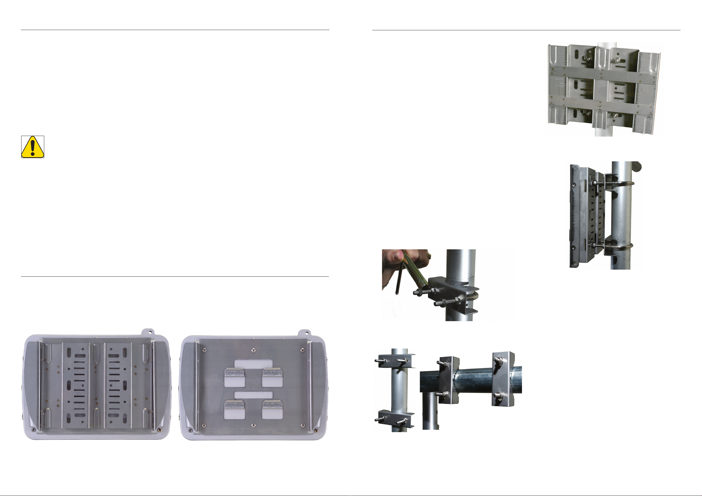
Pole Mounting
1. Insert the two U-bolts through the holes in the claw-
toothed pole-gripper piece.
2. On each U-bolt, place a washer, a lock washer, and a nut.
Smaller pole diameters usually require a second nut as a
spacer to hold the bracket away from the U-bolt clamp.
Finger-tighten the nuts. There should be about 12-15 mm
(1/2-5/8”) of U-bolt sticking past the second nut.
Mount the second U-bolt. Use the mounting bracket as a guide
to correctly space the two U-bolts, then tighten the nuts. A
horizontal pole-mount is also shown for reference.
Use lock washers and nuts to secure the bracket to the U-bolts.
Installation on a horizontal pole is the same, you just use dif-
ferent holes in the mounting plate.
This shows the use of spacer nuts when mounting to smaller
poles. You may nd an open-end wrench useful for tightening
the inner nuts in these applications.
Using Mounting Straps
For poles with diameters larger than 50 mm (2”), irregularly
shaped poles, or light poles, you can use mounting straps (not
supplied) to mount the HotPort enclosure.
1. Position the universal mounting bracket against the pole.
2. Thread two mounting straps around the pole and through
the slots located near the top and bottom of the universal
mounting bracket. Secure the mounting straps.
3. Attach the enclosure to the universal mounting bracket by
sliding the metal clips on the back of the enclosure into the
metal straps on the universal mounting bracket.
Secure the enclosure to the universal mounting bracket using
the four captive screws on the sides of the universal mounting
bracket.
Mounting Antennas
Now that you’ve attached the Universal Mounting Plate, you are
ready to proceed to the next steps. Most outdoor applications
use separately-mounted antennas, if so, mount your antennas
now. If you are using the temporary staging antennas, the next
step is to attach the HotPort node itself.
U-bolt Mounted
on Pole
U-bolts, Vertical and
Horizontal Mounting
Universal Mounting Bracket
Attached to Pole
Mounting Bracket
Showing Use of
Spacer Nuts
Mounting Bracket
Your HotPort node shipped with a two-piece mounting bracket.
This bracket is of the same design as the HotPort 6202 outdoor
bracket, so you can install a 7200 in place of a 6201 or 6202.
The assembly is shown below. To mount the node, remove the
outer piece, by loosening the thumb screws.
The inner bracket can be left attached to the node, as shown
below.