Firetide HotPort 7010W User manual

HotPort
Firetide Installation Guide
HotPort7010(W) MeshNode
Published July, 2016

ii HotPortFiretideInstallationGuide
Firetide, the Firetide logo, Reliable connectivity anywhere, HotPort and HotPoint are all
trademarks of Firetide, Inc. All other trademarks are the property of their
respective
owners.
Information in this document is subject to change without notice.
Firetide, Inc.
2105 S. Bascom Avenue, Suite 220
Campbell, CA 95008
USA
www.firetide.com

iii
About this document
Thissectionliststheaudience,purpose, summaryofinformation,and
conventionsused in this document.
Audience
ThisdocumentisintendedforcertifiedprofessionalswhoinstallFiretidewireless
solutions.
Purpose
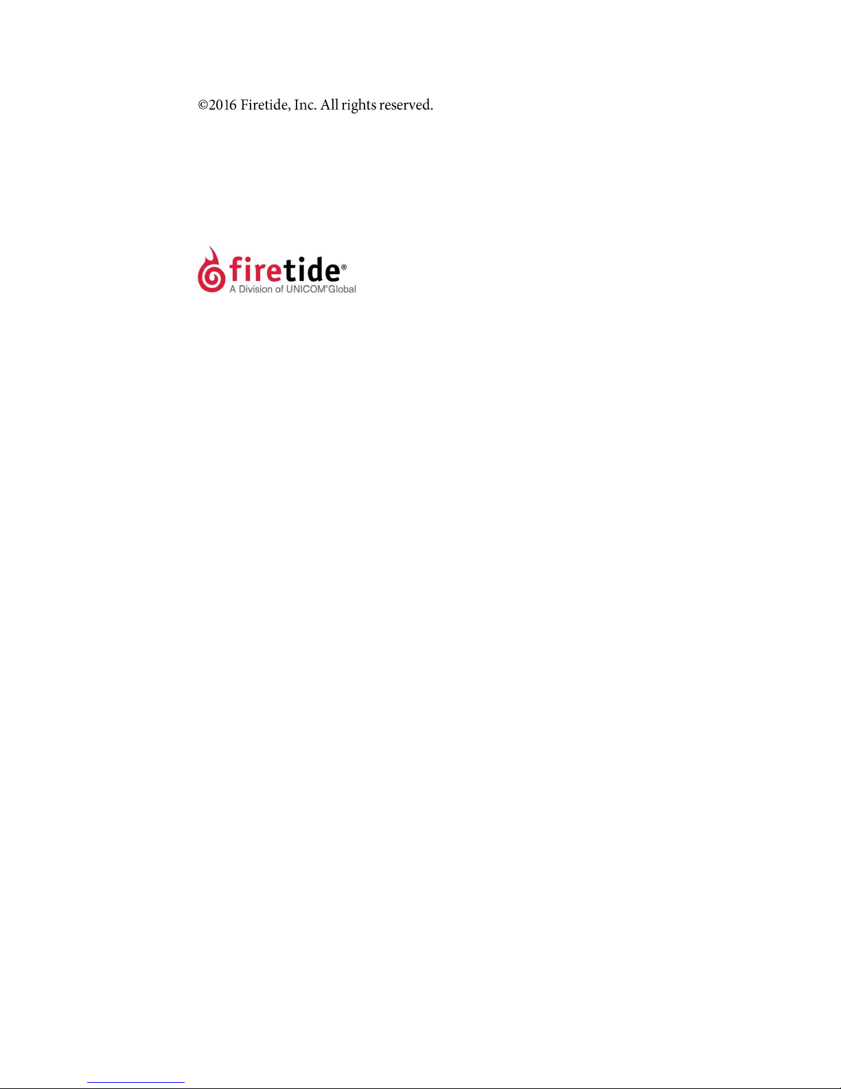
Thisdocumenthas theinformationandproceduresnecessary toinstalland
do
basictestswithFiretideHotPort7010(W) mesh node.
Conventions
Certain information has special meaning for the reader. This information appears
with an icon that indicates a particular condition, such as a warning or caution,
oralabel,suchas“Note”or“BestPractice”.
Electricalhazards
arethose environmentswhere the danger of
electrocutionisprobable.Thisimageappears beforeeachelectrical
hazard statement.
Warnings
contain safety information that you must obey. If you do
not obey the instruction in a warning, the result mightincludeserious
injury or death. This imageappears before each warningstatement.
Cautions
contain information that you should obey to avoid minor
injury,inconvenience,anddamagetoequipment.Thisimageappears
beforeeachcautionstatement.
Notes
contain optional advice and information particular to a special case or
application.
Best practices
contain specific recommendations based on industry-standard
expectations.
Document feedback
If you find an error or content missing from this document, we want to hear
about it. You cansend your feedback about any of our documents to
techpubs@firetide.com.
!

iv
Contacting customer support
If you need support, depending on the problem, you might be asked for this
information:
•
Description of the problem
•
ComputerwithHotView Proandaninstalled managementlicense
•
Channel and frequency plans
•
Recent spectrum analysis
•
Device topology in Google Earth (KMZ file)
•
Network map ortopologyplan with the names and device information
You must also have administrator access to the mesh to be able to receive
technical support.
Thenexttableliststhecontactinformationforcustomersupport.
Worldwide customer support
Days/Hours
Contact
Americas
Monday to Friday
7:00amto5:30pmPST
(Pacific standard time)
http://www.firetide.com/requestsupport
1 (877) FIRETIDE, extension 2
+1(408)399-7771,extension 2
+1(408)355-7271
Africa
Monday to Friday
http://www.firetide.com/requestsupport
Asia
8:00 am to 5:30 pm IST
+918040215111
Australia
(India standard time)
Fax +1(408) 317-2257
Europe

v
Contents
About this document iii
Audience .........................................................
iii
Purpose ...........................................................
iii
Conventions ....................................................
iii
Document feedback .........................................
iii
Contacting customer support...........................
iv
........................................................... iv
HotPort 7010(W) mesh nodes 1
Before you permanently installa HotPort 7010(W) mesh node 1
Preparing what you need to install
2
Box contents for an outdoor mesh node
2
Parts of an outdoor mesh node ........................
2
Ground screw
3
LEDs
3
Ports
3
Pressurereliefvalve
4
Resetbutton
4
Antenna connectors
4
Sun shield
5
Testbeforeyouinstall....................................
5
Required material that is not included
6
Required tools that are not included
6
Certification requirement
6
Doing the tests
6
HotPort 7010(W) mesh node installation 10
Tools required .................................................
10
Doing a site survey ..........................................
10
Safe installation practices ...............................
11
Preparing a mesh node for installation ...........
12

vi
Preparingearthground ...................................
13
Installing a mesh node and antenna assembly14
Opening the mount bracket .............................
15
Attaching the mesh node to a wall
17
Attaching a mesh node to a vertical pole
17
Attaching a mesh node to a horizontal pole19
Attaching straps
20
Troubleshooting
22
Cannot see a mesh node in HotView Pro ...........
22
After multiple reboots a mesh node is missing22
Performance not as expected...........................
22
Resetting an outdoor mesh node to factory default settings23
Power connection ............................................
23
Connector pin and cable information 24
HotPort 7010(W) AC power connector...............
24
Custom power cables .........................................
24
Weatherproof procedures
25
Tools and materials ..........................................
25
Makingweatherproofcabletonode connections25

1
HotPort 7010(W) mesh nodes
Firetide HotPort
TM
meshnodescomefromthefactory with two radiosthat
operates in 802.11a,b, and g mode. Youcan enable
802.11n touseMIMO,or
configurethemeshnodetooperateinothermodeswith
HotView Pro.
Licensesenableothersoftwarefeatures.
The next table lists the radio, included software license, and the modelnumber
that appears in HotView Pro.
Radio
Software license
(included)
HotView Pro
model number
—
Two radios
7012
SW-7000-MIMO
Two radios, 802.11n-capable MIMO
7102
TouseMIMO,youmusthaveoneMIMO license for each meshnode.OneMIMO
license is sufficient for all of the radios in one mesh node. A MIMO license
enables a mesh node for all radios currently licensed or licensed in the future.
If you plan to use DFS, you must take the web-based training class. After you
pass the class, Firetide will give you login credentials so you can configure DFS
withHotViewPro.
Before you permanently install a HotPort 7010(W)
mesh
node
Before you install an outdoor mesh node in a permanent location, you need to
makesureyouhaveallofthecorrectcomponentsandmakesurethecomponents
areoperational.
Note:
You must complete the training program and be certified by Firetide to be
able to install Firetide products.

HotPort 7010(W) mesh nodes
2
Preparing what you need to install
To get what you need to set up a mesh node:
1.
Open the box.
2.
Removethecontents.
3.
Checkthecontentsfordamage.
If a part is missing or damaged, call your Firetide reseller.
4.
If the contents are good and correct, keep the box for future use.
Box contents for an outdoor mesh node
Anoutdoormodelcomeswiththeseitems:
•
HotPort meshnodewith weatherproof capsina NEMA-4Xenclosureand
sun
shield with a two-piece mounting bracket
•
Six detachable 2.4/5 GHz omni-directional antennas
•
TwoNtoreverse-polaritySMAadapters
•
Mount bracket for 3.7 to 5 cm (1.5 to 2.0 inch) diameter poles or a wall
•
Mount kit
-
U-bolts,M6x1.0-80mm, withflatwashers,split washers,nuts
-
Claw-tooth pole grippers
-
M6x1.0-40mm hex bolt
-
M6x1.0-20mm hex bolt
-
Hex-head socket wrench
•
AC weatherproof plug assembly (AC cable not included)
Note.
AC connector with cables can be purchased from Firetide.
Parts of an outdoor mesh node
The next picture shows theconnectors and LEDs on thebottom panel o f a
HotPort 7010(W)meshnode.Weatherproofcapsprotecttheconnectors.
Forinformationabout cablesandaccessories approvedforusewith
Firetide
devices, refer to the
Accessory Cable Guide
.

HotPort 7010(W) mesh node
3
Radio 1 connectors
G round screw
AC Power connector
Ethernet ports
Radio 2 connectors
Pressurerelief valve/
Reset button
Ground screw
The ground screw is in the upper left hand corner of the bottom panel. You must
ensure adequategrounding for the meshnode.
LEDs
ThebottompanelhastheseLEDs:
•
Power, which is a greencolor when the device receives power. The LED is dark
when themesh node does not receive power.
•
StatusLED:
-
Steady greencolor when the systempassesstart-uptests.
-
Dark when themesh node is not ready.
-
Blinks green when the device resets.
•
Mesh. Each radio LED comes on when a neighbor connects to that radio. The
LEDs are dark when there is no neighbor.
Ports
Ports 1 through 4 on a HotPort 7010(W) mesh node are switch ports, similar
to the 7010 mesh node. Like the 7010 mesh node, Port 1 can receive power
from an 802.at compliant PoE source.

HotPort 7010(W) mesh node
4
Pressure relief valve
The pressure relief valve is on the bottom panel. If you need to remove the valve
toresetthe meshnode,turnitbyhandoruseawrench.Ifyouremovethevalve
cover only, you can see the valve. See the next image.
Pressure relief valve
Reset button
The reset button is onthe bottom panel and is covered by a pressure relief
valve. You can remove the valve to do a factory reset of the mesh node. See
“Resetting an outdoor mesh node to factory default settings” onpage 24.
Antenna connectors
Thenextpictureshowsthebottompanel with two antenna connectors for each
radio
.
Radio 1 connectors
Radio 2 connectors

HotPort 7010(W) mesh node
5
Sun shield
The next picture shows the sun shield that covers the chassis. Four Phillips-head
screws hold the sun shield to the chassis.
Test before you install
You should set up and test the mesh nodes indoors on a table before you install
theminpermanent locations.
The benefits of tests before you install include:
•
Make sure all of the equipment works before you install it
•
Consistent settings across mesh nodes to reduce software configuration
errors in the field
•
Test the bandwidth and makesurethat the radios work

HotPort 7010(W) mesh node
6
Typesof tests to do:
•
Power on each device
•
Attach all antennas and make sure you can see all devices in HotView Pro
software
•
Data and other application throughput tests
•
Learn to position the antennas with the antenna alignment tool
For more information about the antenna alignment tool, see the
Firetide
HotView Pro Reference Manual.
•
Train installation personnel
Required material that is not included
You must purchase and install a 50 ohm terminator on each unused antenna
connector of active radios. This protects the transmitter. A rubber, metal, or
plastic cap is not a replacement for a terminator.
Required tools that are not included
HotView Pro network management software and appropriate licenses are
required. Before you set up the network, you must purchase all licenses from
your Firetide distributor.
For the procedures related to license installation, refer to the
HotView Pro
Reference Manual.
Certification requirement
Allpeoplewhoinstall and manage networks that contain Firetide products must
comply with the training and certification requirements of the installation.
Doing the tests
For efficiency, you can configure six to eight mesh nodes at one time.
Todo tests and capture data with HotView Prosoftware:
1.
Put the mesh nodes on a table.
2.
Attach the power cable to each mesh node.
3.
Attach the staging antennas to each mesh node:
-
OFDM - one antenna per radio
-
MIMO - two antennas per radio (only one radio can be tested using
the contents in the 7010(W) packaging

HotPort 7010(W) mesh node
7
4.
Single-click to start the Quick Launch feature of HotView Pro, which opens
the server and client software at the same time.
5.
Login with the correct user nameand password. The default user name is
hv_admin; and the default password is firetide.
The system initializes.
6.
Goto
Mesh>AddMesh>
loginwiththedefaultusernameandpassword.
7.
Make sure that all of the mesh nodes are visible in HotView Pro.
If you cannot see any or all of the mesh nodes, see the troubleshooting
information in the
HotView Pro Product Guide
.
8.
All nodes intended for use in the United States (US) will be set to use the US
Country Code. For all nodes set to be used outside of the US, a prompt to
enter a iCountry Code will appear.
Caution:
Make sure you configure the device for the correct country. If
youdo not configure the country correctly, the device might operate in a
manner that is not legal or create problems with other wireless devices.
!

HotPort 7010(W) mesh node
8
a.
Select the country of operation from the drop-down list.
b.
Click
SetCountry CodeNow
.
When you set thecountry code the systemrefreshes themeshconfiguration
and gives all visible nodes the same country code. For a few minutes the
meshnodesmightappearanddisappearfromthegraphicmeshrecordin
HotView Pro.
c.
Wait for three minutes for the system to finish the refresh.
9.
Toconfigure mesh-wide settings, go to
Mesh > Configure Mesh...
-
Set the operational mode as needed.
-
Set the extended range feature if the distance between the mesh
nodes is more than 0.8 km (0.5 mile). Todetermine the longest link,
you measure the distance between the mesh nodes on a map, such as
Google Earth.
-
Set the hop optimization feature if there might be hidden node
interference.
Note:
For information about specific features and theconfiguration process, see
the HotView Pro Reference Manual.
10.
Right-click a specific meshnode toconfigure mesh node-specific settings if
needed.
11.
Checknetwork throughput from end to end and for each link with several
wireless clients. For procedures, see the
HotView Pro Product Configuration
Guide
.
Note:
If youarenotabletoget themeshtosendandreceivedata,see
“Troubleshooting”on page22.
12.
If this node will have a long RF path or if you use narrow beamwidth antennas
in the installation, set the mesh RSSI threshold to be -93 dBm.
Note:
This RSSI change prevents mesh instability because of flapping links.
13.
Do throughput tests:
a.
Right-click on one of the two nodes between which you want to
measure performance.
b.
Select
Run Diagnostics Tools
, and select the second node from the
menu.
c.
Select the type of throughput test:
-
Ping
-
TCPIperfandbi-directionalTCPIperf
-
UDP Iperf and bi-directional UDP

HotPort 7010(W) mesh node
9
d.
Click
Execute
.
14.
After you finish the tests, remove the staging antennas.
Caution!
The staging antennas are not rated for outdoor use.
You are now ready to permanently install the mesh nodes.
Power Input
100-240 VAC , 50-60 Hz, 0.8 A
Port 1 : IEEE 802.3at compliant PoE-PD
!
Environmental Specifications
Operating temperature: -20o C to + 60o C
Storage temperature: -30o C to +70o C
Humidity (non-condensing): 10% to 90%
Storage humidity (non-condensing): 5% to 95%
Max altitude: 15,000 ft (4,600 meters)
FCC Part 15.21 Note
,QIRUPDWLRQWR8VHU
The user’s manual or instruction manual for an intentional or
unintentional radiator shall caution the user that changes or
modifications not expressly approved by the party responsible
for compliance could void the user's authority to operate the
equipment. In cases where the manual is provided only in a
form other than paper, such as on a computer disk or over the
Internet, the information required by this section may be
included in the manual in that alternative form, provided the
user can reasonably be expected to have the capability to
access information in that form.

HotPort 7010(W) mesh node
10
HotPort 7010(W) mesh node installation
After you do tests and configure the mesh nodes, then you are ready to install
the mesh nodes in a permanent outdoor location.
The work process is:
1.
Gather all required tools.
2.
Do a site survey to make sure that no new safety hazards are present.
3.
Preparesafetyequipmentandconfirmearthgroundprocedures.
4.
Attach the mesh nodes and antennas to poles that attach to a mast, tower,
or roof.
5.
Install the mesh node and antennas assembly and other devices, such as
cameras or access points toa permanent location.
Tools required
To install HotPort 7010(W) mesh nodes, you need to use:
•
#2 Phillips screwdriver
•
Small adjustable wrench
•
Wire cutters to cut tie wraps around cables
•
Electrical tape and butyl mastic tape to weatherproof the connectors
•
Sprayto prevent corrosion
Otherequipmentyoumightneedincludes:
•
Ladder
•
Lifttruck
•
Safety equipment
Doing a site survey
Before you install any equipment outside, check the entire site:
•
Toidentifypossiblehazardsthatmightbenewsincethecompletesitesurvey
•
Toidentify the presence of objectsthat might cause interference for the
radios
Warning!
Certified professionals must install Firetide products. Failure
to install this equipment correctly can result in equipment damage,
personal injury, or death.

HotPort 7010(W) mesh node
11
Electricalshockhazardwarning!
Makeaplantokeeptheinstallation
personnel safe.
Warning!
Do not install Firetide products where possible contact with
power lines can be made. Antennas, poles, towers, guy wires, or cables
can touch power lines. People can be injured or killed if they touch or
hold any part of the equipment when it contacts electric lines. Make
sure that equipment and personnel cannot directly or indirectly
contactpowerlines.
Warning!
Do not openthe cover:
•Dangerousvoltagesinside.
•No serviceable parts inside.
•Refer to certified service personnel.
Safe installation practices
Bestpractice:
InstallHotPort7010(W)meshnodesonpolesthatarea
sufficient
distancefrompowerlines.
The horizontal distance from a tower, pole or antenna to the nearest power line
should be at least twice the total length of the pole/antenna combination. This
distance ensures that the pole will not contact a power line if it falls during or
after installation.
•
Select equipment locations that allow safe and simple installation.
•
Do not work alone.
•
Useapproved non-conductingladders,shoes,andothersafetyequipment.
Make sure all equipment is in good condition.
•
If a tower or pole begins falling, do not catch it.
•
Ifawireorpoletouchesapowerline,donottouchit.
•
Do not install antennas or towers on windy days.
•
Make sure all towers and poles are correctly grounded. Make sure all
electrical cables connected to antennas havelightning arrestors.
A connection to earth ground and a lightning arrestor can prevent fire
damage or personal injury in case of lightning, static build-up, or short
circuit within the equipment connected to the antenna.
•
Use 10 AWG ground wire and corrosion-resistant connectors to connect the
base of the antenna pole or tower directly to the building protective ground
or to one or more approved groundingrods.
•
Refer to the National Electrical Code for grounding information.

HotPort 7010(W) mesh node
12
Preparing a mesh node for installation
It is easier to install all devices to one object, such as a pole, and then attach the
pole assembly to the roof. If you attach the devices to a pole attached to the roof
top, factors, such as weather, can make the installation more difficult and
dangerous.
Warning!
Only use antennas that are rated for outdoor applications.
W
arning!
Failure to comply with these installation instructions might
resultinseverepersonalinjuryincludingelectricalshockorpermanent
damage to equipment.
Warning!
Make sure that all safety equipment is in good condition. Do
notusebrokenordamagedtools or equipment.Always usesafework
practices and obey all local and national guidance for earth ground
requirements and electricity.
Note:
Collect all tools before you install the mesh nodes.
Make sure that you have antennas rated for outdoor use. For information
about antennas and how to select them, see the
Firetide Antenna and
Accessory Guide.
Note:
Install the antenna and any other wireless devices higher than the HotPort
meshnodeor accesspoint.
1.
To a pole that you can install at a permanent outdoor site, attach these
items:
a.
Bracket for the mesh node
b.
Antenna bracket
c.
(Optional) Otherdevices
2.
Attach the antennato the antenna bracket. Refer to the installation
proceduresfor theantenna.

HotPort 7010(W) mesh node
13
Preparing earth ground
Warning.
A HotPort mesh node must be correctly connected to earth
ground. Failure to do so can result in equipment damage, injury, or
death.
Theproductwarrantydoesnotincludedamagefromincorrectgrounding.Obey
all local building and electrical codes regarding antennas. If not available, refer
to the National Electric Code (NEC).
Earth groundingguidelinesinclude:
•
If you attach a mesh node and antenna to a tower or pole, attach the base of
the tower pole to the building’s ground or to one or more approved
groundingrodswith10AWGgroundwireandcorrosion-resistant
connectors.
•
Connect the grounding cable to rain gutters only if the rain gutter is
connected to earth ground.
•
Ground rods are copper-plated and 1.8 to 2.4 meters (6 to 8 feet) long.
•
Install all ground components in straight lines. If you must make a bend, do
not make a sharp bend.
•
Earth-to-ground should be less than or equal to 10 ohms.
•
Somesalt compounds are corrosive and can cause copper ground rods to
corrode.
To prepare the soil for groundrods:
1.
If the soil contains rocks or sand, insert the ground rods into the ground
2.
Pull out the ground rods.
3.
Put in an approved ground enhancement material into the holes where the
grounding rods go.
4.
Put in the ground rods.

HotPort7010(W) meshnode
14
Note:
Gather and take all tools and materials with you to the installation site.
Warning!
Donotinstallthisproductonawindyorrainyday.
Toinstall a mesh node and antenna assembly in a permanent outdoor location:
1.
Safelylift and carefully put the assembly on the roof.
2.
Attach thepole to which themesh node and antenna are attached to a mast,
tower, or roof.
-
Attach the cables that have integrated lightning arrestors, or attach
the cables and install lightning arrestors.
-
Makedrip loops withcables.
-
Connect earth ground. See “Preparing earth ground”on page 13.
3.
Makeallconnectorsweatherproof.See“Weatherproofprocedures”on
page
25.
4.
AttachallothercablesincludingtheAC power cable.
5.
Cover all unused connectors.
6.
(Optional) Use plastic tie wraps to keep cables organized.
7.
Verify that the mesh node works:
-
Ping the IP address
-
Useoneormoremeshnodes
-
Do throughput tests with HotView Proand record theresults as a
benchmark test
Installing a mesh node and antenna assembly
The process to install a mesh node to a mast or tower is the same as a roof
installation.
This manual suits for next models
1
Table of contents
Other Firetide Network Hardware manuals