FIREWOLF
INSTALLATION
INSTRUCTIONS
FWC-FSLC-SMK, FWC-FSLC-SMKALG,
BY
NAPCO
FWC-FSLC-HEAT, FWC-FSLC-SMK6B
& FWC-FSLC-SMK4B
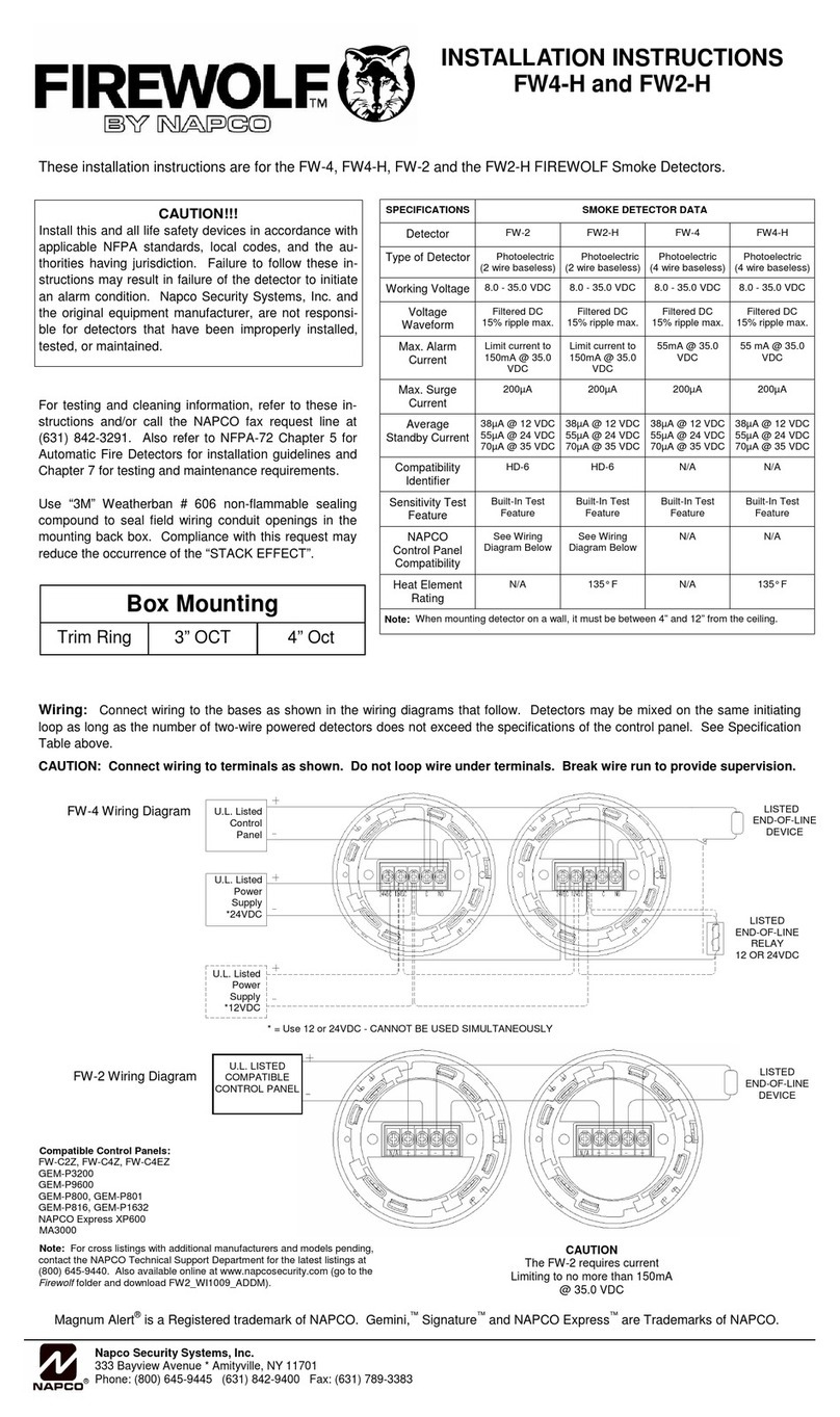
These
insta
ll
ation
i
nstructions
are
for
the
FWC-FSLC-SMK,
FWC-FSLC-SMKALG,
FWC
-
FSLC
-
HEAT
smoke
sensors
and
FWC-FSLC-SMK6B,
FWC-FSLC-SMK4B
analog
bases
.
These
instructidns
apply
to
all
Napco
DCP
(D
i
gital
Communication
Protocol)
analog
sensors
and
bases.
These
units
must
be
irlstalled
and
maintained
in
accordance
with
app
l
icable
N.
F.
P
.A.
standards,
l
oca
l
codes
and
any
au
thority
having
jurisd
i
ction.
Please
refer
to
N.F.P.A.
72
Standard
for
Automatic
Fire
Detectors
for
installation
guidelines
and
testing
proced
ur
es
.
Smoke
detectOrs
sho
ul
d
be
tested
upon
completion
of
installation
and
at
least
semia
nn
ua
lly t
hereafter,
in
accordance
wit
h
N.F.P.A.
72,
section
on
"Inspection,
Tes
ts
and
Maintenance
".
To
insta
ll
the
detector,
insert
the
detector
into
the
base.
Turn
the
detector
clockw
i
se
until
it
stops
. T i
ghten
tamper
screw.
Use
"3M
"
Weatherban
#606
nonflammab
le
sealing
compound
to
sea
l
field
wi
ri
ng
conduit
openings
in
the
mounting
back
box.
Compliance
with
this
request
may
reduce
the
occurrence
of
th
e
"STACK
EFFECT
".
SP
E CI
FICATIONS
CATEGORY FWC-FSLC-SMK FWC-FSLC-SMKALG FWC-FSLC-
HEAT
FWC-FSLC-SMK6B FWC-FSLC-SM
K4
B
Absolute
Maximum
41.0
VDC 41.0VDC
41.0
VDC
41.0
VDC
Applied
Voltag
e
39
.5
VDC
Operating
Vo
l
t'C\e
Ran
ge
('M)
(S-S
)
22.9
-
39.5
VDC
24 -
40
.7VDC
24
-40.7VDC 24 -
40
.7
VDC
24
-
40.
7
VDC
Sensit
i
vity
Range
SEE
CHART
BELOW
SEE
CH
ART
BELOW
57
.
2°C-
65.5°C
N/A
N/A
(135°F-150°F)
C
urrent
Consumption
390
)-l
A
Typ
i
cal
390
J-l
A
Typical
350
J-l
A
Typical
N/A N
/A
(S
-
SC)
Norma
l
Mode
ROOJ-<1
\ Maxi
mum
540
J-lA
Maximum
500
J-lA
Ma
xi
mum
Cu
rr
ent Consum£tion
(S
-
SC)
Wh
en
Po
ed
2mA
2mA
2
mA
N
/A
N/A
Al
arm
C
urr
ent
(S-SC)
(S
ee
Base)
(S
ee
Base)
(See
Bas
e)
8mA
(Typ
i
cal)
BmA
(Typica
l)
Re
mot
e
LED
C
urrent
(See
Base)
(S
ee
Ba
se
) (
See
Base)
BmA
(Typica
l)
8mA
(Typi
ca
l)
Dev
i
ce
Type
Code
88
Hex
88
Hex
98
Hex
N/A N/A
Operating
Temperature
-l0°C -sooc -
10°C-
50°C
-10°C-
50
°C
-10°C
-
50°C
-10°C-
sooc
(WF-
l22°F)
(WF-
122°F)
(WF-
122
°F)
(WF
-122°F)
(14°F
- 1
22°F)
UL
~
ste
d
temperatur
e
0°C-
37
.
8°C
0 c -
37
.8 c
0°
C-
47°C
0°
C -
47°C
0
°C
- 4
7"
C
(32°F
-
100
°F)
(32°F
- I
00
°
F)
(32°F
-IIS"
F)
(32°F
-
!15
°F)
(32°F
-
115°F)
-
Storage
Temperature
-
-2
0"
C"=""
GO"
c-
'
"o"
e----
~
6o•
e
-«O"
c-=-
60°C
(~4-;,F~
-
t4o
o'F)
-
6Q
u
(.
'-
(-
4°F-
140
°F)
(-4°F -
140
°F)
(-4°F -
140
°F)
(-4°F -140°F)
Test
• * * N/A N/ A
Dimensions
3-
15
/16"0 X l-1/2
"H
3-15/16"0
X 1-1
/2"H
3-15/
16"0
X 1-9/
16"H
5-7/8"0 X I
5/3
2
"H
4-1
/B
"D X 5/ 16"H
Env
ironment Indoor
Use
O
nl
y Indoor
Use
Only
Indoor
Use
Only
Indoor
Use
On
ly Indoor
Use
Only
Visual
Al
ar
m/ Dual LED Dual LED Dual LED S'
ee
Sensor
See
Sensor
Power
Indicator
Add
r
ess
Setting
* * * N/11. N/A
*=See
Contro
l
Panel
For
proper
address
setting
a
nd
testing
procedure.
SE
NSITIVITY
RANGES
VELOCITY
(fpm) FWC-FSLC-SMKALG
(%/ft
.)
FWC
-FSLC-SMK (%/ft.)
BOX
MOUNTING
300 .
88-
3.57 0.5 3.80
BASE
3"
-0
4"
-0
4"-S
2000 .88 -2.81 0.5 -
2.
74
FW
C
-F
SL
C-SMK6B
YES
YES YES
4000 .88 2.52 0.5 - 2.68
FW
C-
FSLC
-
SMK4B
YES
NO
NO
<'
WARNING!!
!!
A
TIENTION
!!!!
Failure
to
fo
ll
ow
these
instructions
ma
y
INSTALLATION
WIRING
result
in
the
failure
of
the
detector
SHALL
NOT
EXCEED
to
initate
an
alarm
condition
.
Napea
50
OHMS
(14
-
18
AWG.)
is
not
responsib
le
for
detect
ors
MA
XIMU
M
OF
1
CONDUCTOR
that
hav
e b
ee
n
improperly
in
sta
ll
ed,
PE R
TERMINAL.
tested
or
mai
n
tained.
TM
Firewolf is a Registered trademark
of
NAPCO
.
~
Napco
Security
Systems,
Inc.
~
333 Bayview
Av~nue
*A
mityv
ille,
NY
11701
WI1
709 l
"
Phone
: (800) 645-9445 (631) 842-9400 Fax: (631) 789-3383
PG
1
OF
2
NAP
CO
'


