Fireye BLPS-25 User manual

1
®
DESCRIPTION
The BLPS, TS350 and TS752 Series of pressure and temperature sensors are designed for
use with the PPC4000 Fuel Air Ratio Controller and BurnerLogix Burner Management
System with Integrated Boiler Control.
The pressure sensors (P/N BLPS-x) utilize a solid state pressure transducer to indicate
steam pressure. The temperature sensors (P/N TS350-x and TS752-x) utilize a platinum,
positive temperature coefficient sensing element to provide indication of water tempera-
ture, stack temperature, boiler water temperature of a steam boiler, and outdoor air temper-
ature. The pressure sensors have a maximum overpressure specification of 200% Full Scale
Output and 800% Burst. The pressure sensors are equipped with a 1/4" NPT male fitting.
The Immersion Style Temperature Sensors have a 1/2" NPT mounting for the 2", 4" and 8"
thermowell probe.
The pressure and temperature sensors provide a 4-20 mA control signal over their respec-
tive stated ranges to the PPC4000 and BurnerLogix Control systems. No setting or calibra-
tion is required for either type of sensor.
The PPC4000 and BurnerLogix Control systems perform continuous safety checks on the
operation of all pressure and temperature sensors to insure their safe and proper operation
(e.g. under range, over range, open wiring, etc.).
WARNING: The PPC4000 Fuel Air ratio Controller and BurnerLogix Control
System must only be used with the approved pressure and temperature sensors.
(e.g.: BLPS-15, TS350-4, etc.). Do not use with any other types of pressure or tem-
perature sensors. UL approval requires these sensors.
BLZPTS-1
NOVEMBER 19, 2013
PRESSURE AND
TEMPERATURE
SENSORS
for use with the
BURNERLOGIX
Burner Management
System and
PPC4000 Series
Fuel/Air Ratio
Controller
TS350
TS752
BLPS

2
GENERAL SPECIFICATIONS
Temperature Sensors:
Temperature Measurement Range:
TS350-X: 32°F to 350°F (0°C to 176°C)
TS752-X: 32°F to 752°F (0°C to 400°C)
RTD Type: Platinum, 100 ohms +-0.1% @32°F (0°C)
Temperature Coefficient: .00385 ohms/ohms/C
Output: 4-20 mA, linear with temperature
Operating Temperature Range: -13°F to 185°F (-25°C to 85°C)
Accuracy: +/- 0.75% of span
Thermowell Case: 300 Series stainless steel
Mechanical Fittings: 1/2-14 NPT
Pressure Sensors:
Pressure Measurement Range: 0 to 15, -14.7 to 25, 0 to 30, 0 to 200, 0 to 300 psig
Excitation Voltage: 9-30Vdc (supplied by BurnerLogix control)
Accuracy: +/- 0.25% Full Scale (at constant temperature)
Output: 4-20 mA, linear with pressure
Maximum Over Pressure: 200% of full scale
Maximum Burst Pressure: 800% of full scale
Operating Temperature Range: -40°F to 185°F (-40°C to 85°C)
Fitting: 1/4" NPT Male
Electrical: 1/2" Conduit and Terminal Strip
Fireye P/N Description
BLPS-15 Pressure transducer, 0 to 15 psi (0 to 1030 mb), 4-20 mA output linear with pressure. ¼" NPT mount-
ing. Screw terminal connections and conduit adapter cover.
BLPS-25 Pressure transducer, -14.7 to 25 psi (-1013 to 1720 mb), 4-20 mA output linear with pressure. ¼" NPT
mounting. Screw terminal connections and conduit adapter cover.
BLPS-30 Pressure transducer, 0 to 30 psi (0 to 2070 mb), 4-20 mA output linear with pressure. ¼" NPT mount-
ing. Screw terminal connections and conduit adapter cover.
BLPS-200 Pressure transducer, 0 to 200 psi (0 to 13.8 Bar), 4-20 mA output linear with pressure. ¼" NPT mount-
ing. Screw terminal connections and conduit adapter cover.
BLPS-300 Pressure transducer, 0 to 300 psi (0 to 20.7 Bar), 4-20 mA output linear with pressure. ¼" NPT mount-
ing. Screw terminal connections and conduit adapter cover.
TS350-2 Temperature sensor, Range 32°F to 350°F (0°C to 176°C), 4-20 mA output, linear with temperature.
Insertion length is 2 inches. Stainless steel thermowell included with ½"-14 NPT mounting.
TS350-4 Temperature sensor, Range 32°F to 350°F (0°C to 176°C), 4-20 mA output, linear with temperature.
Insertion length is 4 inches. Stainless steel thermowell included with ½"-14 NPT mounting.
TS350-8 Temperature sensor, Range 32°F to 350°F (0°C to 176°C), 4-20 mA output, linear with temperature.
Insertion length is 8 inches. Stainless steel thermowell included with ½"-14 NPT mounting.
TS752-2 Temperature sensor, Range 32°F to 752°F (0°C to 176°C), 4-20 mA output, linear with temperature.
Insertion length is 2 inches. Stainless steel thermowell included with ½"-14 NPT mounting.
TS752-4 Temperature sensor, Range 32°F to 752°F (0°C to 176°C), 4-20 mA output, linear with temperature.
Insertion length is 4 inches. Stainless steel thermowell included with ½"-14 NPT mounting.
TS752-8 Temperature sensor, Range 32°F to 752°F (0°C to 176°C), 4-20 mA output, linear with temperature.
Insertion length is 8 inches. Stainless steel thermowell included with ½"-14 NPT mounting.
Note: BLPS-25 is not compatible with the Burnerlogix Control System

3
®
APPROVALS
Underwriters Laboratories Inc.:
MCCZ File MP1537
Controls, Primary Safety - Listed
MCCZ2 File MP1537
Controls, Primary Safety - Component
MCCZ7 File MP1537
Controls, Primary Safety Certified for Canada
MCCZ8 File MP1537
Controls, Primary Safety Certified for Canada - Component
Factory Mutual: FM Class 7610
Acceptable by: Industrial Risk Insurers (I.R.I.)
FIGURE 1. Pressure Sensor - BLPS-15, -25, -30, -200, -300
COM OUT
GND
EXC
4
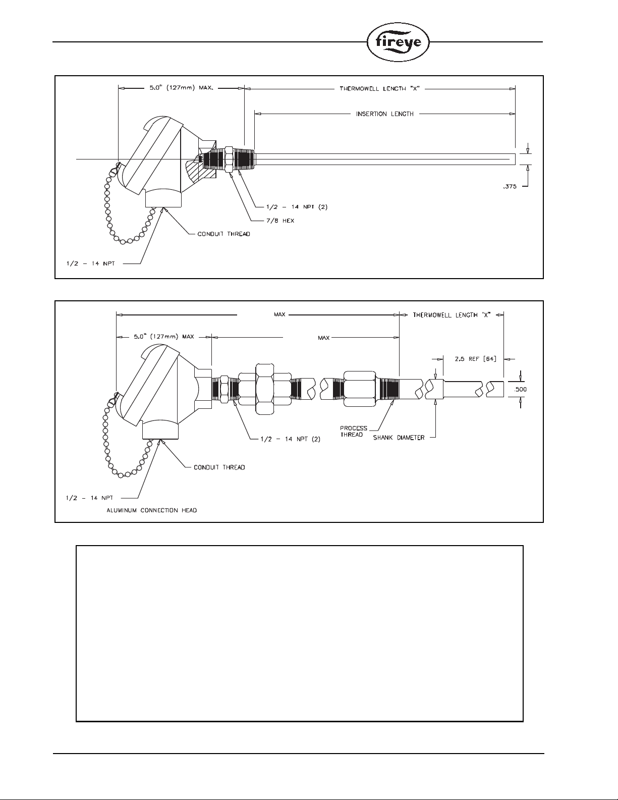
FIGURE 2. Temperature Sensor - TS350-2, TS350-4, TS350-8
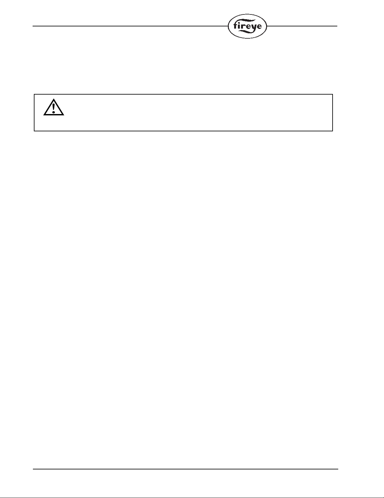
FIGURE 3. Temperature Sensor - TS752-2, TS752-4, TS752-8
0.625”
X = 2”, 4” or 8”
11.0” [279]
7.5” [191]
WARNING:
1. Read these instructions carefully. Failure to follow them could result in a hazardous or
dangerous condition.
2. Insure that the range of the selected sensor is appropriate for the application. Note: A
general rule to follow when selecting the sensor range is that the expected value of the
monitored pressure or sensor should fall between 40-70% of the upper range of the sensor.
For example, a steam boiler maintains 20 lbs. pressure, select the BLPS-30 Pressure Sensor,
with a 0-30 PSIG range
3. The sensors must be located where the ambient temperature will not exceed the maximum
ambient operating temperature specified for the sensor.
4. Insure that the pressure range programmed on the BurnerLogix Boiler Room Control
matches the installed pressure sensor. Refer to Bulletin BLZ-1001.
5. Do not mount any of the sensors where they could be used as a footstep.
6. Installation must be
p
erformed b
y
a trained, ex
p
erienced flame safe
g
uard technician.

5
®
MOUNTING PRESSURE SENSORS
Note: Refer to Figure 4.
1. The steam pressure sensors (BLPS-15, -25, -30, -200, -300) provide a 1/4” NPT male fitting for
connection to the steam header. Included is a 1/4” coupling.
2. Make sure the boiler is shut down and zero steam pressure exists in the boiler vessel.
3. Disconnect power to the boiler controller so the boiler cannot sequence during installation of the
steam pressure sensor.
4. Always mount the steam pressure sensor above the water line of the boiler.
5. Locate the pressure sensors where the ambient temperature will not exceed 185F
FIGURE 4.
6. Although the unit can withstand substantial vibration without damage or significant output
effects, it is good practice to mount the pressure sensor where there is minimum vibration.
7. A steam trap (siphon loop) must be connected between the boiler and the pressure sensor to pre-
vent boiler scale and corrosive vapors from affecting the pressure sensor element.
8. Use only a small amount of pipe compound to seal the connection joints. Excess pipe compound
may clog the fitting and prevent proper operation of the sensor.
9. Make all pipe connections in accordance with approved standards.
10. When tightening the sensor, apply a wrench to the hex flats located just above the pressure fit-
ting. DO NOT tighten by using a pipe wrench on the housing. Do not tighten the pressure sensor
by hand.
MOUNTING TEMPERATURE SENSORS
The immersion style temperature sensors have a ½" NPT mounting for the 2", 4" and 8" thermowell
probes, and a ½" conduit fitting.
HOT WATER
Note: Refer to Figure 4
1. Disconnect power to the boiler controller so the boiler cannot sequence during installation of the
hot water temperature sensor.
2. The thermowell must be mounted where it is always exposed to the circulation of the hot water
3. If the water system is full, drain the system below the point where the thermowell will be
installed.
4. Tap an appropriate size fitting. (2", 4" and 8" thermowell have ½"NPT fitting).
5. Insert the appropriate thermowell (2", 4", or 8") and tighten.
6. Fill the system to check for leakage.
WARNING: The electro-mechanical high steam limit and/or high hot water temperature
limit MUST REMAIN in the running interlock circuit of the flame safeguard control.
STEAM PRESSURE
OR HOT WATER SENSOR
ELECTRO-MECHANICAL
HIGH LIMIT
(STEAM OR WATER)
6
LEAD/LAG OPERATION: When two hot water boilers are set-up for lead/lag operation, a hot
water temperature sensor must be installed for each boiler.
STANDBY WATER TEMPERATURE
1. Disconnect power to the boiler controller so the boiler cannot sequence during installation of the
standby temperature sensor.
2. The thermowell must be mounted where it is always exposed to the circulation of the hot water.
3. If the water system is full, drain the system below the point where the thermowell will be
installed.
4. Tap an appropriate size fitting (2", 4" and 8" thermowells have 1/2" NPT fitting).
5. Insert the appropriate thermowell (2", 4", or 8") and tighten.
STACK TEMPERATURE
1. Use the existing well connection for the stack temperature sensor if provided by the boiler man-
ufacturer.
2. If no well connection is provided, select an appropriate location for mounting the temperature
sensor. Preferably as close to the boiler outlet as possible.
OUTDOOR AIR TEMPERATURE
1. The outdoor air temperature sensor should be mounted on the outside of the building where it
will be exposed to representative air temperature, but not to direct sunlight. A sun shield may be
required.
2. Mount the temperature sensor high enough so it cannot be covered with snow, leaves, or other
debris, or be tampered with. Vents from the building should be avoided.
WARNING: Location of the temperature sensor to monitor boiler water temperature of a
steam boiler is critical. The sensor should be mounted where it is always exposed to the cir-
culation of the boiler water, not too close to a hot or cold inlet or steam coil. Consult the
boiler manufacturer for guidance on the sensor location.

7
®
WIRING SENSORS
PRESSURE SENSORS
1. All wiring must be in accordance with National Electrical Code and local codes, ordinances, and
regulations.
2. Sensor housing provides connection for 1/2" conduit.
3. The pressure sensors require 2 conductor, 18 gauge, shielded cable. Power limited, rated for
300V @105C. Use Belden 9318 or equivalent.
4. The shield should be connected to the earth ground terminal on the wiring base of the Burner-
Logix Control (Terminal #E) or to the common ground established in the cabinet. The shield
should be taped at the sensor to avoid unintended contact with the sensor housing.
5. All sensor wiring should be in a separate conduit. DO NOT install sensor wiring in any conduit
or junction boxes with high voltage wiring.
6. Maximum wiring distance for sensor wiring is 100 feet.
7. See Table 1 for wiring terminations to the Burnerlogix
8. See Table 2 for wiring connections to the PPC4000.
TEMPERATURE SENSORS
1. All wiring must be in accordance with National Electrical Code and local codes, ordinances, and
regulations.
2. Sensor housing provides connection for ½" conduit.
CAUTION: Disconnect power supply from the BurnerLogix Control before connecting
wires to prevent electrical shock and equipment damage.
For 4-20 mA output,
use + EXC and - COM terminals
COM OUT
GND
EXC
4
312
For 4-20 mA output,
use terminals 1 (+) and 2 (-)
MINCO
Measurement Specialties
Temperature Specialists Inc.
For 4-20 mA output, For 4-20 mA output,
use terminals (+) and (-) use terminals 6 and 7
8
3. The temperature sensors require 2 conductor, 18 gauge, shielded cable. Power limited, rated for
300V @105C. Use Belden 9318 or equivalent.
4. The shield should be connected to the earth ground terminal on the wiring base of the Burner-
Logix Control (Terminal #E) or to the common ground established in the cabinet. The shield
should be taped at the sensor to avoid unintended contact with the sensor housing.
5. All sensor wiring should be in a separate conduit. DO NOT install sensor wiring in any conduit
or junction boxes with high voltage wiring.
6. Maximum wiring distance for sensor wiring is 100 feet.
7. SeeTable 1 and 2 for wiring terminations.
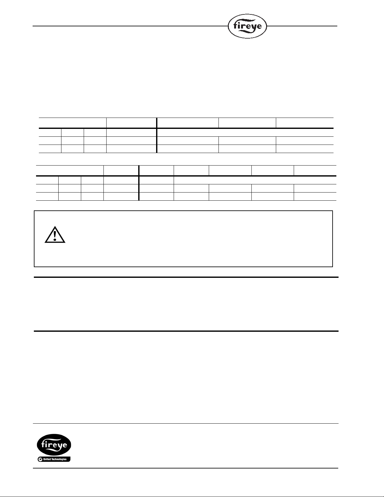
Table 1: Burnerlogix wiring connections
Table 2: PPC4000 wiring connections
NOTICE
When Fireye products are combined with equipment manufactured by others and/or integrated into
systems designed or manufactured by others, the Fireye warranty, as stated in its General Terms and
Conditions of Sale, pertains only to the Fireye products and not to any other equipment or to the
combined system or its overall performance.
WARRANTIES
FIREYE guarantees for one year from the date of installation or 18 months from date of manufacture
of its products to replace, or, at its option, to repair any product or part thereof (except lamps and
photocells) which is found defective in material or workmanship or which otherwise fails to conform
to the description of the product on the face of its sales order. THE FOREGOING IS IN LIEU OF
ALL OTHER WARRANTIES AND FIREYE MAKES NO WARRANTY OF MERCHANT-
ABILITY OR ANY OTHER WARRANTY, EXPRESS OR IMPLIED. Except as specifically
stated in these general terms and conditions of sale, remedies with respect to any product or part
number manufactured or sold by Fireye shall be limited exclusively to the right to replacement or
repair as above provided. In no event shall Fireye be liable for consequential or special damages of
any nature that may arise in connection with such product or part.
TS350/TS752 BLPS PCV AUX1 AUX2
Minco Meas Sp Temp Sp BurnerLogix Terminals
1+ 1+ 6+ + EXC X (WHT/BLU) X (WHT/BLU) X (WHT/BLU)
2- 2- 7- - COM 11 (WHT/GRN) 22 (WHT/VIO) 23 (BRN/WHT)
TS350/TS752 BLPS PCV AUX1 AUX2 SENS4 SENS5
Minco Meas Sp Temp Sp PPC4000 Terminals
1+ 1+ 6+ + EXC P11.2 P11.2 P11.3 P11.3 P11.3
2- 2- 7- - COM P11.10 P11.9 P11.8 P11.7 P11.6
CAUTION: PROGRAM AND SET-UP
The proper operation of the BurnerLogix System and the pressure and temperature sen-
sors requires that the selected pressure ranges are appropriate for the application and
must match the pressure range programmed on the BurnerLogix Control. Insure that the
range of the selected sensor is correct for the application and the pressure range pro-
grammed on the BurnerLogix Integrated Flame Safeguard and Boiler Controller matches
the installed pressure sensor. Refer to Bulletin BLZ-1001.
FIREYEBLZPTS-1
3 Manchester Road NOVEMBER 19, 2013
Derry, New Hampshire 03038 USA Supersedes November 6, 2013
www.fireye.com
This manual suits for next models
10
Table of contents
Other Fireye Accessories manuals


