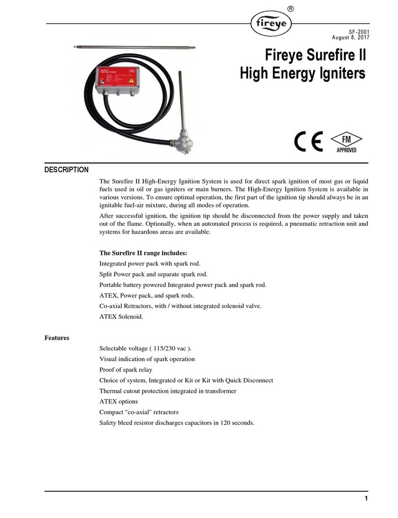
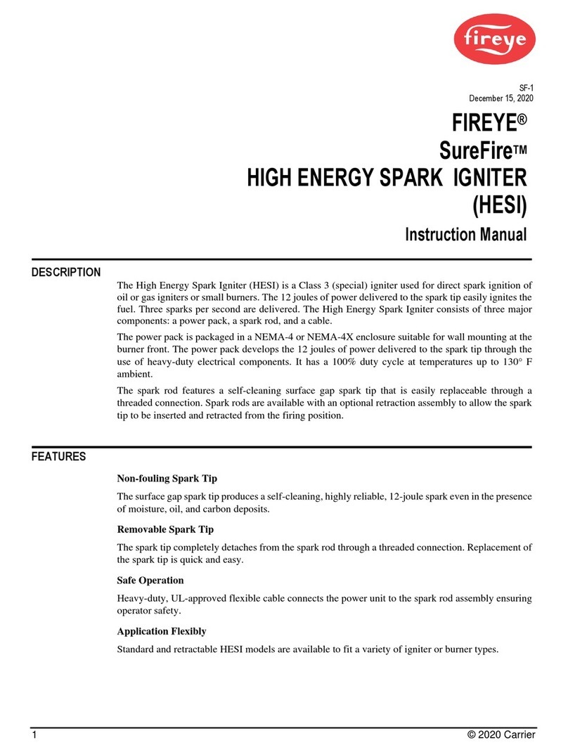
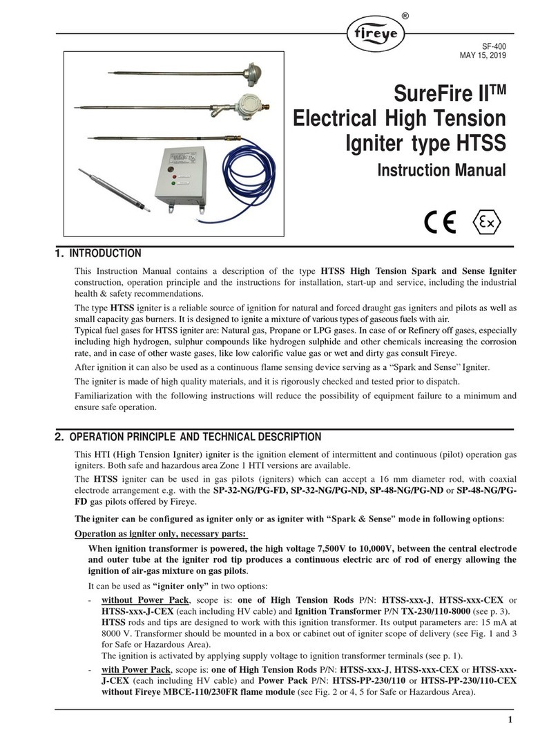
Fireye SureFire II HDHESI User manual

1 © 2020 Carrier
1. INTRODUCTION
This Instruction Manual contains a description of the type SureFire II™HDHESI Heavy Duty High Energy Igniter
construction, operation principle and the instructions for installation, start-up and service, including the industrial health
& safety recommendations.
Type HDHESI igniter is designed for direct ignition of gaseous or liquid fuels like light and medium oil, heavy oil
which can be steam, air or mechanically atomized.
The igniter creates 3 sparks per second of a very high energy of 24 Joules per spark, sufficient for self-cleaning
of the rod tip and for direct firing of heavy fuels in particularly difficult operating conditions e.g. in wet, dirty
(slag, ash, unburned fuel) environment.
In case of special fuels or difficult operating conditions consult Fireye before ordering.
This High Energy Igniter is intended for intermittent operation as Class 3 Special igniter.
The igniter is made of high quality materials, and its components are rigorously checked and tested prior to dispatch. No
moving parts and parts requiring adjustment ensure long and trouble-free operation at low service costs.
All of this makes HDHESI a reliable and effective source of direct ignition of gas burners and oil burners in heavy duty
applications.
Familiarization with the following instructions will reduce the possibility of equipment failure to a minimum and ensure
safe operation.
FIGURE 1. SureFire II™Heavy Duty HESI Igniter – main components.
SF-700
December 17/, 2020
SureFire II™
Heavy Duty
High Energy Spark Igniter
(24 Joules per Spark )
Instruction Manual

2 © 2020 Carrier
2. TECHNICAL SPECIFICATION AND OPERATION PRINCIPLE
HDHESI is a High Energy Igniter, working on the principle of cyclic discharging of a capacitive system by a spark
gap, generating 3 sparks of very high energy of 24 Joules per second on igniter rod tip.
Igniter construction
To order a complete HDHESI igniter please specify the following components (see Fig. 2):
– a Spark Rod: 16 mm outer diameter, with replaceable high resistant tip “class 60 Joules” of fixed gap between
electrodes, equipped with j. box IP67 and male cable connector, reference (insertion) length L = 0.8 to 5.0 m;
Part Number HE-ROD-24-xxx where “xxx” is the rod length L e.g. “1.3” means 1.3 m (see Fig. 2).
– the HV Cable: two wire, shielded, OD 15 mm², 4,5kV max, wire 1,5 mm², 5 m long (or 10 m), with female
cable connector on rod side; Part Numbers are: HEC-24-5 (optional 10 m long P/N HEC-24-10).
– the Power Pack: 230 or 115 VAC (selectable in power pack), rated for 3 sparks of 24 J each per second, with
a gland for ignition cable. Power pack printed board including HV transformer 230/115VAC/1150VAC, HV
capacitors, spark gap, circuit components, terminals is mounted in a carbon steel, powder coated IP66
enclosure;
Part Number HE-PP-24, includes: the door key, mounting lugs and a HV cable gland. Stainless Steel version
of Power Pack enclosure is available on request - contact Fireye.
Igniter operation
During the burner Trial for Ignition the HDHESI igniter is activated by connecting the power pack to a power
supply. Before it is connected check if the correct voltage has been selected on the Power Pack HV transformer
terminals (230VAC or 115VAC is prewired following the order spec). If not, make proper connections following
p. 4, wiring diagram Fig. 4 and Fig. 8. Once energized, the HV ignition transformer generates an 1150 VAC for
secondary circuit. This voltage is doubled to 2300V and rectified. HV capacitors are charged to the level at which
the spark gap causes energy discharge and the cycle is repeated. At the moment of discharge, current flows via HV
cable to the tip of the rod and creates a powerful spark of 24 Joules at the end of the rod tip (see Fig. 2, 4, 6),
between the central positive electrode and the grounded rod outer tube (negative electrode).
After the Trial for Ignition the SureFire II™HDHESI igniter must be disconnected from the power supply.
The circuit is equipped with discharging resistors which allows a quick discharge of capacitors, below 90
seconds, from when the igniter power supply is disconnected.
Only after this period the power pack enclosure can be opened, and service works can be undertaken.
The igniter is designed for continuous use, however the type of applications for which he is intended to be
used is intermittent operation. Following applicable standards, typical Trial for Ignition operating time is 5 - 10
seconds, repeatable in short periods. Operating time in such cases should not exceed time of few minutes. In order
to protect the device from unintentional continuous operation, adequate time delay protection must be
provided in the control system.
The igniter Power Pack can be equipped with a spark proof relay confirming the igniter operation. A rail mounted
current overflow indicator for mounting outside of the power pack, can be offered on request only.
Application features
The design of the unit provides a very stable and repeatable 3 sparks per second of 24J each.
Replaceable, high strength and durable rod tip does not require regular cleaning due to the high energy of the spark.
It is provided with a concentrically arranged electrodes which ensures a constant distance between them.
The use of replaceable tip, high quality materials used and lack of parts requiring adjustment ensures long operation
with low maintenance costs.
Basic principles on the HDHESI igniter use
a) Rod should be mounted in a guide tube of diameter not less than 1”.
In case of very hot and/or dirty applications guide tube should be cooled/purged by air.
b) During ignition, igniter rod tip location should be at least 100 mm deep in the burner fuel cone (zone of the air-
fuel mixture), close to the nozzle of the burner (see Fig. 3).
c) After ignition the rod has to be retracted at least 400 mm back in such a way that rod tip should be hidden
at least 100 mm deep in guide tube (see Fig. 3).
d) Fireye offers coaxial retraction systems, refer to SF-2001 High Energy Igniter technical bulletin.

3 © 2020 Carrier
e) Strictly observe the temperature limits for individual parts of the igniter - see p. 3. In the case of expected
work at the limit of permissible operating temperatures, appropriate measures should be taken (e.g.
change of the mounting position and method of fixing, use of purge-cooling air).
f) In special or difficult applications, consult Fireye.
FIGURE 2. SureFire II™Heavy Duty HESI Igniter.
FIGURE 3. Use of SureFire II™Heavy Duty HESI Igniter on oil burner – basic principles of rod positioning.

4 © 2020 Carrier
FIGURE 4. Electric wiring diagram of Heavy Duty HESI Igniter.
NOTICE: CONNECT THE HDHESI IGNITER PARTS ACCORDING TO THE WIRING DIAGRAM IN
INSTRUCTION MANUAL.
WARNING: CHECK BEFORE CONNECTING THE IGNITER POWER PACK TO THE MAINS SUPPLY
WHAT SUPPLY VOLTAGE IS AVAILABLE ON SITE. CHANGE SUPPLY VOLTAGE FROM 230VAC
TO 115VAC IF NECESSARY.
NOTICE: POWER AND GROUNDING SHOULD BE CONNECTED IN ACCORDANCE WITH THE
IGNITER WIRING DIAGRAM (SEE FIG. 4), WITH PARTICULAR ATTENTION TO THE CORRECT
GROUNDING TO THE PLANT GROUNDING SYSTEM.
NOTICE: THE SAFETY INSTRUCTIONS IN THIS INSTRUCTION MANUAL SHOULD BE OBSERVED
DURING INSTALLATION, OPERATION AND MAINTENANCE.
WARNING: ALL WORK ON BURNER INSTALLATION MAY ONLY BE CARRIED OUT WEARING
PROTECTIVE CLOTHING, INCLUDING: PROTECTIVE UV-BLOCKING GLASSES, HARD HAT AND
GLOVES.
WARNING: STRICTLY OBSERVE THE TEMPERATURE LIMITS FOR A PILOT AND IGNITER ROD
MOUNTED INSIDE AND THE POWER PACK. IF THERE IS A RISK OF OVERHEATING, CHANGE
THE ROD POSITION OR USE COOLING AIR.

5 © 2020 Carrier
FIGURE 5. HESI Igniter Rod junction box wiring.
FIGURE 6. Heavy Duty HESI Igniter Power Pack layout
FIGURE 7. Connection of supply voltage 230VAC / 115VAC and HV cable to the rod on Power Pack board

6 © 2020 Carrier
3. TECHNICAL DATA
Power supply voltage; current: 230/115 VAC (50/60 Hz) switchable, at approx. 1.8/3.6 A, 220VA
Transformer output voltage: 1,150 VAC (RMS)
External protection: 8 A, fuse type D (both voltages)
Secondary circuit max. voltage: 2,300 VDC (output terminals to rod)
Method of operation: intermittent, 3 electrical sparks per second x 24 Joules each (72 Joules per
second)
Operation rating: 100% (see remarks in p. 2)
Operating temperature, IP rating:
– Power Pack P/N HE-PP-24 -40°C ÷ +65°C, IP66
– Rod P/N HE-ROD-24-xxx -60°C ÷ +80°C, IP67 junction box, +300°C rod tube continuously
– Rod Tip P/N HE-TIP-24-L +300°C tip continuously, over +1,000°C in flame for short period
(Trial for Ignition 5 – 10 seconds, repetitive in short periods)
– Cable P/N HEC-24-5 or HEC-24-10 -60°C ÷ +180°C
Rod outer diameter, outer tube material: 16 mm, 316 SS
Available rod insertion length L: 0.80 ÷ 5.00 m
Rod Tip P/N HE-TIP-24-L working length: 685 mm
HV cable: two wire, shielded, OD 15 mm, 4,5kV max, wire 1,5 mm²
Power Pack dimensions (L x W x H) : 250 x 360 x 155 mm
Weight of parts, material:
– Power Pack P/N HE-PP-24 9.8 kg, Carbon Steel powder-coated or Stainless Steel (option)
– Rod P/N HE-ROD-24-0.9 (0.9 m long)1.3 kg with rod tip, Cast Aluminum painted j.box, 316 SS tube
Rod weight adder approx. 0.75 kg per meter
– Rod Tip P/N HE-TIP-24-L 0.7 kg 316 Stainless and Heat Resistant steel
– Cable P/N HEC-24-5 or HEC-24-10 2.0 kg or 4.0 kg
Notes: 1. If the above parameters are different than those required please contact Fireye
2. For Imperial Units please refer to the Appendix 2 Unit Conversion Table
3. Device complies with the requirements of the European Directive 2011/65/EU (RoHS 2)
MARKING: The HDHESI 24 Joule igniter was independently tested and evaluated by the EMC Accredited Laboratory.
Assessment of compliance of the device with the essential requirements of the European directive no. 2014/30/EU was
carried out. Declaration of Conformity was issued, and igniter was CE marked accordingly.
FIGURE 8. How to switch supply voltage 230VAC to 115VAC on HDHESI Igniter Power Pack board

7 © 2020 Carrier
4. MOUNTING OF THE IGNITION DEVICE
4.1 The igniter function of HDHESI is activated by connecting the power pack to a power supply (230 or 115
VAC). So, before it is connected, check the supply voltage (230VAC or 115VAC) and check the connections
on transformer terminals. It should be wired following order spec. to 230VAC or 115 VAC. If they do not
match, change transformer supply wiring following wiring diagram Fig. 4 and Fig. 8.
4.2 The power supply should be connected in accordance with the igniter's schematic diagram of the power pack
board and igniter wiring diagram for power pack and rod (see Fig. 4), with particular attention to the correct
grounding to the plant grounding system, following the local codes.
4.3 Igniter must always be used in accordance with its intended purpose and following approved installation
documentation, operation algorithms and procedures as well as service manuals.
4.4 Check environmental conditions and ensure that the specified operating temperatures of components as in
p. 3 will not be exceeded.
4.5 During the rod mounting and aiming the conditions and recommendations mentioned in p. 2 should be observed
(see also below).
4.6 Rod should be mounted in a guide tube of diameter not less than 1” and a retraction for the HDHESI rod should
be used to retract igniter rod tip to the safe place after Trial for Ignition (please refer to SF-2001 High Energy
Igniter technical bulletin). The tube must allow the rod tip to reach the correct position in primary combustion
zone to ignite the fuel-air mixture and ensure correct operating temperature and tip protection (please follow
recommendations in p. 2 and Fig. 3).
When HDHESI ignition rod is being used in high temperature applications:
- always use retractor with min. stroke 400 mm to pull the tip back inside the guide tube,
- increase the guide tube length so that the rod tip is completely hidden in guide tube when
retracted,
- use purging / cooling air in the tube to cool the rod and push away a dirt.
4.7 Mounting of the igniter in a retractor: the igniter's rod should be placed inside the guide pipe and fixed in the
retractor clamps. Mounting of the igniter in a retractor must be done so as to enable adjustment of the rod tip
position relative to the burner's nozzle. See retractor Instruction Manual SF-2001 and burner manufacturer
recommendations.
4.8 The guide tube should not be placed in the flame.
4.9 The power pack enclosure should be positioned as close to the burner as possible to reduce cable lengths, as
energy is lost with increasing cable length. The control box must be in a location where the temperature does not
exceed at any moment its max. operating temperature. The box should be mounted with cable glands at the
bottom, to reduce moisture as well as dust and dirt ingress.
4.10Choose the correct glands depending on the cable type and environment demands. After installation, check if the
glands are correctly tightened.
4.11The HV cable should be placed away from any hot elements. It is shielded but not armored, so it should be
mounted in conduits, tubes or cable trays in order to reduce the possibility of damage.
NOTICE: CHECK IF THE LOCAL REGULATIONS ALLOW FOR DIRECT IGNITION OF PARTICULAR
BURNER TYPE OF A SPECIFIED TYPE OF FUEL AT A REQUIRED CAPACITY LEVEL USING AN ELECTRIC
SPARK IGNITER
NOTICE: ONLY QUALIFIED AND COMPETENT PERSONS AUTHORISED BY THE PLANT
MANAGEMENT OR MANUFACTURER, ACCORDING TO LOCAL LAW, ARE PERMITTED TO INSTALL,
MAINTAIN AND SERVICE HDHESI IGNITERS
NOTICE: MAKE SURE TO CONSULT THE MANNER OF MOUNTING THE IGNITER WITH THE
PRODUCT MANUFACTURER / DISTRIBUTOR

8 © 2020 Carrier
5. OPERATING INSTRUCTIONS
INDUSTRIAL HEALTH AND SAFETY ISSUES. STORAGE, HANDLING, TESTING:
5.1 The igniter, unless mounted on the burner, should be stored in a dry place, protected against mechanical
damage. Do not hit, step on igniter components.
5.2 The rod should be transported with care, avoiding impact against other objects or bending.
It should not be lifted by its ends to ensure no damage to rod, tip and connections.
5.3 Prior to starting the igniter it is necessary to check the condition of the cable, glands and connector for
mechanical damage and make sure that the power pack enclosure and rod j.box are properly closed and
glands are tightly fixed.
5.4 Powering the igniter's circuit should only be done after complete assembly of the rod, tip and only when
fitted in its operation-ready position at the burner. Check the proper insertion depth inside the burner as well
as the position of igniter rod tip against the gun nozzle - follow the burner Manual.
5.5 Check the correctness of connections of igniter’s components and protective grounding of the igniter rod
and power pack enclosure as well as circuit grounding. Powering the rod outside a burner should only be
done to test its operation.
5.6 The igniter supply should have effective grounding. Correct connection of the grounding of the igniter
should be checked first, then the line can be connected.
5.7 Do not touch, lift, carry the igniter rod or power pack when the igniter is energized or is not disconnected
from a potential source of electrical power.
5.8 Once assembled, the igniter can undergo the functional test. The rod should be positioned clear of
equipment, flammable materials and personnel. If these conditions are met, power can be applied, and device
switched on.
5.9 Do not open the power pack enclosure, disconnect rod tip or HV cable and grounding cables when the
equipment is energized or is not disconnected from potential source of electrical power supply.
5.10 Never use water to wash igniter components when it is connected to source of electrical power.
IGNITER START-UP AND OPERATION:
5.11 During the burner start-up the main voltage 230/115 VAC can be applied to the power pack, provided that
proper wiring conditions as in p. 5.3 to 5.6 have been verified, as well as the correct assembly of the igniter
has been inspected.
5.12 When starting the burner installation from cold conditions after a longer standstill, check the operation of
the ignition device itself without opening the fuel flow to the burner. When power applied:
- check that the retraction system functions correctly: whether the rod tip reaches its working point when is
inserted, and after retraction completely hides in guide tube away from flame zone.
- check if the rod movement is smooth without jams and obstructions, and safe for the operator. Adjust air
valves if necessary. Follow the retraction system instructions in SF-2001 High Energy Igniter bulletin,
- check the presence and repeatability of electrical sparks on the rod tip,
- no other sparking should be visible on rod connections, grounding points and cable glands. Should that be
the case, de-energize igniter immediately and follow the p. 7 instructions.
- in the case of no sparks present at the rod tip during energizing please refer to p. 7.
5.13 If, after above checking, sparks are strong and repeatable a full burner test with fuel can be performed. If
the spark is present but the igniter does not light the fuel, check fuel settings and the presence of fuel at the
nozzle. If the fuel settings are within the recommended range and during the Trial for Ignition the fuel is
present at the burner nozzle the rod position should be adjusted to ensure that the rod tip is in the correct
location. After moving the rod in new position, the test of ignition should be repeated.
5.14 If the flame is present, rod tip is in proper position, but there is no flame confirmation refer to p. 7.
5.15 The igniter’s use for direct ignition of oil fuel may take place only if sufficiently high atomization medium
(steam, air) and oil temperature as well as their proper pressure can be maintained.
5.16 It is recommended to ignite the burner at a low fuel flow and with a limited quantity of combustion air.
It is further recommended to use shut-off valves with a slow opening and fast closing capability.

9 © 2020 Carrier
WARNING: DO NOT PERFORM ANY MODIFICATIONS TO THIS EQUIPMENT AND
NEVER USE UNAUTHORIZED SPARE PARTS AS THIS WOULD RESULT IN A BREACH
OF THE APPROVALS CONDITIONS AND COULD PROVE HAZARDOUS TO YOUR
HEALTH AND LIFE !
6. PERIODICAL MAINTENANCE AND REPAIRS
The equipment manufacturer recommends a thorough inspection of the igniter every six months if possible, to
ensure long life and reliability.
CAUTION, DANGER HIGH VOLTAGE !
BEFORE ANY WORK ON IGNITER IS UNDERTAKEN, DISCONNECT THE POWER PACK
POWER SUPPLY AND WAIT 90 SECONDS.
ONLY THEN THE POWER PACK ENCLOSURE MAY BE OPENED OR CABLE AND ROD
DISCONNECTED.
STRICTLY FOLLOW THE RULES OF ELECTRICAL EQUIPMENT SERVICE !
INSPECTION OF THE IGNITER'S ROD:
6.1 Disconnect the power source, wait 90 seconds, then open the power pack enclosure and disconnect the HV cable
and igniter rod. Disconnect the rod and retractor and slide out from guide tube and retractor cylinder. Unscrew
the rod's tip.
6.2 Check the condition of the rod tip, central electrode, the ceramic insulator and tip thread joint. The parts must be
clean, not burnt, ceramic not broken and should not bear any traces of high temperature influence, erosion or
mechanical damage. If the rod's tip is damaged, it must be replaced. Clean the tip and remove all traces of erosion
and overheating.
6.3 Check the rod surface for mechanical damages or bending. The rod cannot be bent or squashed. The outer pipe
must not be burned or cracked. In case of excessive damage, replace the rod.
Open the rod junction box cover and check the condition of the cables and terminals. The inside of box and cables
must be clean and should not bear any traces of mechanical or thermal damages. In case of water ingress traces
check the condition of box gasket and tightness of glands and gasket from rod side. Check tip contact (socket) on
the rod side, insulator and thread as in p. 6.2. Clean if necessary.
6.4 In the event of any damage that may affect the safety and the rod performance - replace or return the part to the
manufacturer for repair.
6.5 Removal of the igniter rod and disconnection of the tip may only be done wearing protective gloves due to the
presence of hot surfaces.
INSPECTION OF THE POWER PACK:
6.6 Disconnect the power source and disconnect the HV cable as in p. 6.1.
6.7 Open the door of the power pack box and check the condition of connections on the power pack board terminals
as well as the condition of glands. Check electrical components on the board - HV transformer, capacitors and
other components for excessive wear, burn marks, loose cable connections and water ingress marks. In the case
of burn marks test the power pack or components, in case of water traces check the power pack tightness. Replace
components or whole power pack if necessary.
INSPECTION OF THE HV CABLE:
6.8 Check cable for nicks or kinks, check the connector. Make sure the cable connector is not damaged and
glands are not loose. In case of damages replace the cable set.
NOTICE: DURING THE INSPECTION HANDLE THE IGNITER WITH CARE. DO NOT
THROW OR BEND THE ROD. PROTECT FROM HITS, OTHER MECHANICAL
DAMAGES, MOISTURE AND DIRT.

10 © 2020 Carrier
7. TROUBLESHOOTING. ELIMINATION OF DEFECTS.
7.1 If the main voltage is present but no electrical sparks are generated at the rod's tip when there is correct voltage
at the HV ignition transformer input and output terminals (if it can be measured), perform the following:
a) Disconnect the power source.
b) Check if the power supply voltage comply with the transformer wiring – see p. 4.
c) Check the condition of the cable and electric connections for possible mechanical damage.
d) Check the condition of the rod, tip and it's screw joint for possible mechanical damage (as in p. 6.2) that
could cause internal electrical breakdown.
e) Follow the guidelines in points 6.3, 6.4 respectively.
f) After opening the door of the power pack box, check visually electrical connections on the board, check HV
transformer, capacitors and other components for burn marks. In the case of excessive wear or burn marks
replace the component.
g) Assembly the igniter, connect the power supply and grounding, make the functional test.
h) If no sparks are generated after the above measures have been taken, replace the original rod tip, reconnect
the power source and make the functional test again, following the rules in this manual.
i) If again no sparks are generated, replace the complete rod, and further the cable and repeat the functional test
each time.
j) If still no sparks are generated, replace the complete power pack and repeat the functional test. If the spark
will appear replace capacitors one by one in broken power pack and further replace the HV transformer.
k) After every step assembly the igniter, reconnect the power supply/grounding and repeat the functional test.
7.2 The main components can be checked the following way:
a) Rod Tip P/N HE-TIP-24-L: check on reference igniter rod.
b) Spark Gap P/N HE-SG-24: check on reference igniter power pack.
c) Transformer P/N HE-TR-1150: disconnect from capacitor C1 apply supply voltage. Measure output voltage
using high voltage probe – the RMS value should be 1,150V, peak 1,650V.
d) Capacitors P/N HE-CAP-10, -2, -05: use a multi-meter with capacitance measurement, disconnect GND bus
and measure capacitor capacity. It should be as per the capacitor specification.
7.3 If the main voltage is present but no electrical sparks are generated at the rod's tip and there is no voltage at the
HV ignition transformer output (if it can be measured), perform the following:
a) Check if the power supply voltage comply with the transformer wiring – see p. 4.
b) After opening the power packbox, check the presence of main supply on the HV transformer input and output
(use high voltage probe). If there is no voltage at transformer output replace the transformer. If there is no
equipment to measure transformer output replace the transformer by a spare one.
c) Assemble the igniter, connect the power supply and carry out the functional test following the above rules.
7.4 If the main voltage is present and the sparking is visible in other places: on rod connections, grounding points
and cable glands, perform the steps as above especially looking for bad connections, cracked cables, rods, bad
grounding connections. Try to identify and correct/replace faulty part. Repeat functional test after every
component replacement following the rules in this manual.
7.5 If there is no flame confirmation on flame safeguard system despite the proper igniter functioning and flame
presence on a burner, check the flame safeguard system and refer to this system manuals.
7.6 For any services and troubleshooting of Fireye retraction system module refer to Bulletin No SF-2001.
7.7 If, after all above measures have been taken, the HDHESI igniter does not work properly, or other igniter failure
occurs, please contact the manufacturer's service department.
7.8 Before any works on igniter circuit, replacing components always disconnect the supply and wait 90 sec. before
opening.
7.9 Before performing any functional tests connect the grounding and only then connect supply.
7.10 Each time before installation check the connection cable for mechanical damages.

11 © 2020 Carrier
8. SPARE PARTS, WARRANTY CONDITIONS
8.1 Igniter operation-consumable parts and suggested spare parts quantity:
- Rod Tip, 685mm long P/N HE-TIP-24-L - one for 4 igniters
- HV transformer 230/115VAC/1150VAC P/N HE-TR-1150 - one for 8 igniters
- Spark gap P/N HE-SG-24 - one for 8 igniters
- Capacitor, 3600 VDC/10μF P/N HE-CAP-10 - one for 8 igniters
- Capacitor, 3000 VDC/2μF P/N HE-CAP-2 - one for 8 igniters
- Capacitor, 3750 VDC/0.47μF P/N HE-CAP-05 - one for 8 igniters
- HV cable, with connector, 5 m long P/N HEC-24-5 - one for 8 igniters
Complete list of igniter spare parts Part Numbers is in Table 3.
8.2 HDHESI construction includes two wearing parts:
- Rod Tip, long P/N HE-TIP-24-L - lifetime 1,000,000 sparks
- Spark gap P/N HE-SG-24 - lifetime 200,000 sparks
ATTENTION: Above lifetime refers to laboratory test conditions.
In the real combustion chamber environment, these values are lower. In the case of the rod tip: work in high
temperature conditions, corrosive properties of fuel, impacts and mechanical damages and in the case of oil
fuel ignition oil residues and slag on the tip after its withdrawal (possible burning out), impacts on the slag -
can significantly reduce the tip's life.
In the case of the spark gap lifetime it is influenced by the high temperature, the power supply stability and
the mode of operation of the igniter.
8.3 The warranty (see page 16) does not apply to spark gap P/N HE-SG-24 and ignition rod tip P/N HE-
TIP-24-L as the life time of these parts depend on the quantity of ignition cycles and the conditions
they have to work under.
Each rod tip and spark tube has one month warranty to be checked on receipt or within 1 month, for damage
and tested for the proper functioning. Fireye should be notified of any failure. After 1 month, the warranty
on tip expires.
8.4 This guarantee covers delivered devices and materials under conditions of proper installation, start-
up, operation and maintenance, it means the use in accordance with applicable instructions and
manuals.
This is particularly applicable to overheated parts i.e. working above their maximum operating
temperature defined in Instruction Manual.
8.5 The defective device or part will be replaced or repaired at manufacturer’s option.
The warranty applies to and may be executed only on a failed device send to the manufacturer warehouse for
examination or warranty repair.
8.6 The manufacturer does not accept liability for damage to persons or property resulting from:
– mechanical damages, overheating,
– improper installation, operation, maintenance of igniter contrary to the instructions in the user manual,
– unauthorized igniter modifications or repairs made by unauthorized personnel,
– use of components or spare parts other than original.
8.7 During the guarantee period any repairs or parts replacements must be carried out by the manufacturer service
department, or the user, upon the service's notification and consent.
8.8 Replacement of the consumables can be user-performed only after expiration of the guarantee.
NOTICE: BEFORE THE GUARANTEE PERIOD EXPIRATION ANY REPAIRS OR
PART REPLACEMENT MAY ONLY BE CARRIED OUT BY AN AUTHORIZED
MANUFACTURER SERVICE.
AFTER WARRANTY SERVICE CAN BE CARRIED OUT ONLY BY QUALIFIED AND
COMPETENT PERSONS AUTHORISED BY THE PLANT MANAGEMENT OR AN
AUTHORIZED MANUFACTURER SERVICE.

12 © 2020 Carrier
9. STORAGE
SureFire II™HDHESI Electrical Igniter should be stored in a clean, dry environment and in its original packaging if
possible.
In the case of long length rods always keep them in a horizontal position by supporting both ends and in the middle. The
igniter should also be protected from contamination using the original packaging or wrapping it with foil.
Storage over 30 days: relative humidity of no more than 85%, temperature below 50°C.
NOTICE: THE MANUFACTURER RESERVES THE RIGHT TO CARRY OUT
MODIFICATIONS TO THE PRODUCT DESCRIBED IN THIS INSTRUCTION
MANUAL AT ANY TIME AND WITHOUT ANY ADVANCE NOTICE.
10.ORDERING INFORMATION
Before ordering, please provide the data as in Appendix 1.
The Tables below show examples of the HDHESI Rod Part Numbers every 0.5 metre, power packs and spare parts for
HDHESI igniter.
To order a complete HDHESI igniter please specify a rod, cable and power pack suitable for your application.
Rod Part Number coding sample:
HE-ROD-24-1.5 - means HDHESI igniter rod of insertion length L = 1.5 metre.
HDHESI igniter rods can be ordered in size increments of 0.1 metre lengths, from 0.8 to 5.0 metres.
Table 1: HDHESI Igniter Rod with junction box, replaceable tip
Part No Description
HE-ROD-24-0.8 HDHESI rod, 0.8 mtr long, with IP67 j.box and replaceable tip: 685mm, for 24 Joules
HE-ROD-24-1.0 HDHESI rod, 1.0 mtr long, with IP67 j.box and replaceable tip: 685mm, for 24 Joules
HE-ROD-24-1.5 HDHESI rod, 1.5 mtr long, with IP67 j.box and replaceable tip: 685mm, for 24 Joules
HE-ROD-24-2.0 HDHESI rod, 2.0 mtr long, with IP67 j.box and replaceable tip: 685mm, for 24 Joules
HE-ROD-24-2.5 HDHESI rod, 2.5 mtr long, with IP67 j.box and replaceable tip: 685mm, for 24 Joules
HE-ROD-24-3.0 HDHESI rod, 3.0 mtr long, with IP67 j.box and replaceable tip: 685mm, for 24 Joules
HE-ROD-24-3.5 HDHESI rod, 3.5 mtr long, with IP67 j.box and replaceable tip: 685mm, for 24 Joules
HE-ROD-24-4.0 HDHESI rod, 4.0 mtr long, with IP67 j.box and replaceable tip: 685mm, for 24 Joules
HE-ROD-24-4.5 HDHESI rod, 4.5 mtr long, with IP67 j.box and replaceable tip: 685mm, for 24 Joules
HE-ROD-24-5.0 HDHESI rod, 5.0 mtr long, with IP67 j.box and replaceable tip: 685mm, for 24 Joules
Table 2: HDHESI Igniter: Power Packs, Cables
REMARK: Please specify the Power Pack requested supply voltage. Power Pack would be prewired accordingly.
Part No Description
HE-PP-24 HDHESI Igniter Power Pack 230/115VAC, 3 sparks/sec. x 24 J, with: lugs, door key, gland
for HV cable
HEC-24-5 HV Cable, shielded, 2 wire, length 5 mtrs
HEC-24-10 HV Cable, shielded, 2 wire, length 10 mtrs

13 © 2020 Carrier
Table 3: HDHESI Igniter: Spare Parts
Part No Description
HE-TIP-24-L HDHESI Rod Tip, Long, length 685mm, for 24Joules
HE-SG-24 Spark Gap 24 Joules
HE-TR-1150 HV Transformer 230/115 VAC / 1150 VAC
HE-CAP-10 Capacitor, 3600 VDC / 10μF
HE-CAP-2 Capacitor, 3200 VDC / 2μF
HE-CAP-05 Capacitor, 3750 VDC / 0.47μF

14 © 2020 Carrier
APPENDIX No 1 Proposal Data Sheet
SureFire II™HDHESI – Heavy Duty High Energy Igniter 24 Joules
Please provide the following data before placing the Order for HDHESI Igniter: 1.
1. Information about End User
— Plant Name: . . . . . . . . . . . . . . . . . . . . . . . . . . . . . . . . . . . . . .
— Owner: . . . . . . . . . . . . . . . . . . . . . . . . . . . . . . . . . . . . . .
— Country: . . . . . . . . . . . . . . . . . . . . . . . . . . . . . . . . . . . . . .
— Localization (address): . . . . . . . . . . . . . . . . . . . . . . . . . . . . . . . . . . . . . .
2.
Insertion length:
— Insertion length “L”:
(see Instruction Manual)
L= . . . . . . [m]
3. Required Ingress Protection Level:
IP
. . . . . . . .
4. The operating temperature range: . . . . .
÷
. . . . . [°C]
5. Special power pack enclosure material:
stainless steel for aggressive atmospheres If YES
check the box
6. Power pack supply:
kind of supply:
230VAC or 115VAC
. . . . . . . . [VAC]
7.
Capacity of burner to be lit:
— Nominal (Max):
. . . . . . . .
[kW]
— Reduced for Ignition (Start capacity):
. . . . . . . .
[kW]
8. Kind of fuel:
type of Oil, Gas, enclose fuel composition sheet
. . . . . . . . . . . . . . . . . .
— Calorific value:
. . . . . . . .
[MJ/kg]
— Pressure: . . . . . . . . [MPa]
— Kinematic Viscosity:
in case of Heavy Oil
. . . . . . . . [cSt]
— Atomization method:
steam, air, mechanical . . . . . . . .

15 © 2020 Carrier
APPENDIX No 2 UNIT CONVERSION TABLE
Quantity
Metric Units
Imperial Units
Length 1 millimetre [mm] x 0.003281 = foot [ft; ’] x 0.03937 = inch [in; ”]
1 metre [m] x 3.281 = foot [ft; ’] x 39.370 = inch [in; ”]
Volume 1 cubic metre [m3] x 35.315 = cubic foot [cu. ft]
Air flow rate 1 cubic metre/hour [m3/h] x 0.589 = standard cubic feet/min [SCFM]
Weight 1 kilogram [kg] x 2.2046 = pound [lb]
Pressure 1 kilopascal [kPa] x 6.895 = pound square inch gauge [psig] x 4.015 = inch H2O
Power (capacity) 1 kilowatt [kW] x 293.1 = million BTU/hr [mmBTU/Hr]
Temperature Deg. Celsius [°C]
Formula:
°C x1.8 + 32 = Deg. Fahrenheit [°F]
NOTICE
When Fireye products are combined with equipment manufactured by others and/or integrated into systems designed or
manufactured by others, the Fireye warranty, as stated in its General Terms and Conditions of Sale, pertains only to the
Fireye products and not to any other equipment or to the combined system or its overall performance.
WARRANTIES
FIREYE guarantees for one year from the date of installation or 18 months from date of manufacture of its products to
replace, or, at its option, to repair any product or part thereof (except lamps, electronic tubes and photocells) which is
found defective in material or workmanship or which otherwise fails to conform to the description of the product on the
face of its sales order. THE FOREGOING IS IN LIEU OF ALL OTHER WARRANTIES AND FIREYE MAKES
NO WARRANTY OF MERCHANTABILITY OR ANY OTHER WARRANTY, EXPRESS OR IMPLIED. Except
as specifically stated in these general terms and conditions of sale, remedies with respect to any product or part number
manufactured or sold by Fireye shall be limited exclusively to the right to replacement or repair as above provided. In no
event shall Fireye be liable for consequential or special damages of any nature that may arise in connection with such
product or part.
Fireye, Inc. SF-700
3 Manchester Road December 17, 2020
Derry, New Hampshire 03038 USA Supersedes May 15, 2019
fireye.com
Table of contents
Other Fireye Burner manuals
Popular Burner manuals by other brands

Jackson Grills
Jackson Grills JGSB-LP owner's manual
elco
elco VECTRON ECO 1.34 operating instructions

Unigas
Unigas HP60 Manual of installation - use - maintenance
Brouwland
Brouwland 90 P manual

Legendfires
Legendfires Phantom 500 Installation and user instructions
Honeywell
Honeywell Eclipse ImmersoJet Design guide
resideo
resideo Q314 manual
Midco
Midco Incinomite J83-DS Installation and service instructions
Sime
Sime MACK 5SP Installation, use and maintenance instructions
Riello
Riello 40 GS10 TL Installation, use and maintenance instructions
Riello
Riello 911T1 Installation, use and maintenance instructions
Riello Burners
Riello Burners PRESS 30N Installation, use and maintenance instructions
