HE-PP-12-INT
HE-L
Hole with inner thread to allow
connection of extension tube
ET 0.5 or ET 1.0
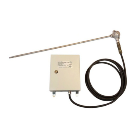
Overview of the different versions
FIGURE 1. Ignition unit with fixed ignition electrode and retraction handle
Assembly: The High Energy System, consisting of the individual parts above, must be assembled by the
user. The advantage is the reduced packed size, and resulting low shipping costs.
The complete length of the ignition rod is adjustable by addition of stainless steel extension tubes, each with
male and female threading, in increments of 0.5 m, other lengths on request. The extension tube ET will be
screwed into the existing 20mm mounting adapter on the side of the power pack housing. Having reached
the desired length, pass the red high tension cable from the tip adapter HE-SSR-0.0 through the tube into the
power pack and mount the tip adapter HE-SSR-0.0. Cut the red high tension cable 330 mm from the inside
of the housing. The last 8mm of the insulation must be removed to allow the supplied ring terminal to be
attached. This must be attached using the appropriate crimping pliers (specifically designed for insulated
self-locking crimped on terminals). The self-locking feature ensures, by engaging at the endpoint, that the
maximum available contact is achieved. This results in the full power, required for the high-energy ignition
system, to be transmitted, allowing the unit to function properly. The ring terminal is attached to the high
tension bolt on the printed circuit board. The ring is placed on top of the plain washer, followed by the ser-
rated lock washer and finally locked on with the nut.
If a short ignition rod required, the tip adapter HE-SSR-0.0 can be screwed directly into the existing 20mm
mounting adapter, and the ignition tip is screwed on.
The shortest available complete ignition rod length is 545 mm by using the HE-SSR-0.0 and the HE-S
(20mm+325mm+200mm= 545mm), by using the HE-L it is 1020 mm.
The power supply cable must be provided by the customer and is not included in the delivery, but can be
offered upon request.
A functioning ignition system consists of the following individual components:
HE-PP-12-INT: Power Pack with handle and rod connection (length 20 mm)
HE-SSR-0.0: Tip adapter, with fix connected 3m high tension cable (other lengths on request)
HE-S or HE-L: Ignition tip HE-S (length 200 mm) or HE-L (length 675 mm)
ET 0.5 / ET 1.0 (if required): ET 0.5 (length 500 mm) and/or ET 1.0 (length 1000 mm)
Carefully read through the whole of this page before first use and observe the information on page 15:
On the external PE connection (protective earth) of the high-energy supply unit, a cable with a minimum
cross-section of 4 mm2must be connected to the earth potential point of the burner (see the assembly
instruction below).
8mm of the insulation of the PE wire must be removed to allow the supplied yellow ring terminal to be
attached, using the appropriate crimping pliers (specifically designed for insulated self-locking crimped on
terminals). The self-locking feature ensures, by engaging at the endpoint, that the maximum available contact
is achieved. This ensures that the full contact is available to provide maximum earth potential, allowing the
system to function correctly. The yellow ring terminal is applied to the external earthing bolt on the casing
with a plain washer first, then the ring terminal, followed by the serrated lock washer and finally the nut.
All other connections, with exception of the power supply cable to be provided by the customer, have
already been made.
6


