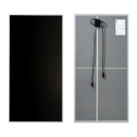
First Solar 6 Series User manual

Global
REV 2.1
First Solar Series 6™ Module |USER GUIDE
PD-5-200-06

i of ii
© 2019 First Solar, Inc. | PD-5-200-06 Rev 2.1 | First Solar Series 6 Module User Guide
COPYRIGHT AND NOTICES
© Copyright 2019 First Solar, Inc. | PD-5-200-06 Rev 2.1 | FIRST SOLAR SERIES 6 MODULE USER
GUIDE. All rights reserved. No part of this document may be reproduced in any form or by any electronic
or mechanical means, including information storage and retrieval systems, without permission in writing
from First Solar.
NOTICE
First Solar reserves the right to make changes in solar module design and/or specications at any time
without notice. Accordingly, the reader is cautioned to verify that data sheets are current before placing
orders or nalizing system permitting and/or design. Information furnished by First Solar is believed to
be accurate and reliable. However, no responsibility is assumed by First Solar or its subsidiaries for its
use; nor for any infringements of patents or other rights of third parties, which may result from its use.
No license is granted by implication or otherwise under any patent or patent rights of First Solar or its
subsidiaries.
CONTACT INFORMATION
For information regarding First Solar and its products, please visit www.rstsolar.com. First Solar has an
extensive library of supporting Application Notes that can be made available upon request from technical
support technicalsupport@rstsolar.com.
GLOBAL
First Solar, Inc.
P.O. Box 730
Toledo, OH USA 43697-0730
Tel: +1 (602) 414-9300
Fax: +1 (602) 414-9400

ii of ii
© 2019 First Solar, Inc. | PD-5-200-06 Rev 2.1 | First Solar Series 6 Module User Guide
1 INTRODUCTION 1
2 SAFETY 2
3 REGULATORY COMPLIANCE 4
4 PRODUCT IDENTIFICATION & RATINGS 5
4.1 PRODUCT IDENTIFICATION & RATINGS 5
4.2 SYSTEM DERATING FACTORS 6
5 HANDLING & STORAGE 7
6 MECHANICAL SPECIFICATIONS 8
7 INSTALLATION & MOUNTING 10
7.1 MOUNTING 10
7.2 MOUNTING LOCATIONS & LOAD RATINGS 11
7.3 TOP MOUNTING 12
7.4 SPEEDSLOT MOUNTING 13
7.5 MODULE ORIENTATION 14
7.6 MODULE SHADING CONSIDERATIONS 14
7.7 INSTALLATION CONSIDERATIONS FOR ARC MODULES 15
7.8 WIRE MANAGEMENT 15
7.9 ELECTRICAL INTERCONNECTION 15
7.10 INVERTER COMPATIBILITY 16
7.11 GROUNDING METHOD 17
8 MAINTENANCE 18
8.1 MAINTENANCE 18
8.2 MODULE CLEANING GUIDANCE 19
8.3 MODULE DISPOSAL 20
9 REVISION HISTORY 21
TABLE OF CONTENTS

1 of 21
© 2019 First Solar, Inc. | PD-5-200-06 Rev 2.1 | First Solar Series 6 Module User Guide
1 INTRODUCTION
This document provides information on First Solar Series 6 Modules of model types FS-6XXX and FS-
6XXXA (“XXX” references the module power rating) for system designers, installers, and maintenance
personnel. Model types FS-6XXXA contain an anti-reective coating (ARC) on the front side surface. Series
6 Modules are designed to have a long operating life and high energy yield when installed, operated, and
serviced in accordance with the instructions in this User Guide. All products within the same model series
classication remain fully compatible with one another, even though there may be slight differences,
provided appropriate system design practices are employed. Read this User Guide thoroughly before
beginning any work related to the installation, operation, or maintenance of the First Solar Series 6
Module.
Please refer to your First Solar Module Warranty Terms & Conditions for module warranty terms and
product return policies. Failure to follow this User Guide may void your warranty.
Keep this User Guide for future reference and provide to all subsequent owners or users of the solar
modules.

2 of 21
© 2019 First Solar, Inc. | PD-5-200-06 Rev 2.1 | First Solar Series 6 Module User Guide
2 SAFETY
All instructions and safety information should be read and understood before attempting to handle, install, or
electrically connect First Solar modules. Failure to follow safety, installation, and handling instructions may
result in injury. Only qualied personnel should install, operate, or maintain PV modules or systems.
Series 6 Modules are designed for 1000V systems at altitudes up to 5000 m (16404 ft) and 1500V systems
at altitudes up to 3000 m (9842 ft) per IEC 61730-1.
Select installation locations and module support structures to ensure modules and connectors (open or
mated) are never submerged in standing water.
DANGER The Series 6 Modules may produce up to 275 Volts DC (VDC) and up to 4.0 Amps when exposed to
sunlight. A single module or multiple interconnected modules can create a lethal shock hazard
during daylight hours, including periods of low light levels. The danger increases as modules are
connected together in series and/or parallel.
DANGER
To avoid re and/or injury due to ground faults and associated electrical hazards:
`Do not unplug PV module connections while under load. Do not disconnect the module connectors during
daylight hours unless the module is in an open circuit condition.
`Replace modules with damaged wires immediately. Keep all array wiring out of reach of non-qualied
personnel.
`Do not concentrate light on the module in an attempt to increase power output.
`Never allow the PV array system voltage to exceed 1500VDC under any condition.
`Replace broken modules immediately.
`Repair ground faults immediately.
`Do not work on modules or systems when the modules or wiring is wet.
`All building mounted PV systems should utilize Ground Fault Detector Interrupters (GFDI) and ARC Fault Circuit
Interrupters to minimize risk of electrical shocks and res.
Series 6 Modules have a maximum series fuse rating of 6.0A as dened by UL 1703 and a maximum
overcurrent protection rating of 6.0A as dened by IEC 61730-1/IEC 61730-2. PV systems should be
designed to comply with and provide module overcurrent protection consistent with local codes.

3 of 21
© 2019 First Solar, Inc. | PD-5-200-06 Rev 2.1 | First Solar Series 6 Module User Guide
The conditions necessary to trigger reverse current overload (RCOL) in Series 6 Modules do not occur
in typical operating modes of a properly installed PV system. The system designer should ensure
that modules are not subjected to RCOL. The use of GFDI devices or other advanced fault monitoring
techniques can signicantly reduce the likelihood of sustained ground faults. Properly selected and
installed string fuses can increase protection against RCOL.
DANGER Reverse currents higher than the rated values for a First Solar module, may result in module failure,
including module breakage due to RCOL. Extreme and continuous RCOL conditions may cause a re
or create electrical shock hazards. To avoid RCOL:
`Maintain equivalent voltage in parallel strings by installing an equal number of modules per string within the
same source circuit. Failure to install modules with balanced voltage in parallel strings can result in voltage
imbalance.
`Incorporate measures to protect modules against RCOL for connections of parallel strings.
Modules damaged because of system-induced RCOL are not covered under the First Solar Module
Warranty. Module warranty eligibility is not affected by the presence, absence, or type of reverse current
protection used in a system design.
CAUTION Wear safety glasses and cut-resistant gloves when working with non-interconnected modules or
system components. Wear electrically rated PPE when working with interconnected modules or
system components. Select PPE based on work consistent with local and/or national standards.
WARNING To avoid risk of re, do NOT interconnect Series 6 Modules with other FS Series Modules (e.g.
– Series 4, Series 3, or Series 2) within the same interconnected string, inverter, or Maximum
Power Point Tracker.

4 of 21
© 2019 First Solar, Inc. | PD-5-200-06 Rev 2.1 | First Solar Series 6 Module User Guide
3 REGULATORY COMPLIANCE
It is the responsibility of the installer and/or system integrator to ensure compliance with all local
structural and electrical codes, which may be applicable to the installation and use of First Solar Series 6
Modules.
`For systems installed in Canada, installation shall be in accordance with CSA C22.1, Safety Standard for
Electrical Installations, Canadian Electrical Code, Part 1.
For systems installed in North America, First Solar Series 6 Modules are Listed by a Nationally
Recognized Test Laboratory (NRTL) to UL 1703, the standard for Flat-Plate Photovoltaic Modules and
Panels. To maintain the modules’ application as a UL Listed product:
`Use only components that have been Recognized or Listed by Underwriters Laboratories (UL) for their
intended purpose.
`Ensure the PV array open-circuit voltage does not exceed 1500 VDC (1000 VDC for UL Canada).
`Install modules with mounting systems that have been evaluated for UL Listed application.
`Protect modules from reverse currents in excess of the 6.0A maximum series fuse rating.
Series 6 Modules are tested and certied per IEC 61730-1/IEC 61730-2 and meet Class II requirements
for 1500VDC systems.
Series 6 Modules are tested and certied per IEC 61215-1/IEC 61215-1-2/IEC 61215-2 for a maximum
system voltage of 1500V.

5 of 21
© 2019 First Solar, Inc. | PD-5-200-06 Rev 2.1 | First Solar Series 6 Module User Guide
4 PRODUCT IDENTIFICATION & RATINGS
4.1 PRODUCT IDENTIFICATION & RATINGS
Each module is equipped with a product label on the back and a laser-etched serial number on the front
glass. The label identies the model number, nameplate electrical ratings, and safety information.
The ratings in Table 1 are UL Listed with a tolerance of ±10% unless otherwise noted.
NOTICE: Electrical specications are subject to change. See label for nal electrical ratings.
Table 1: Model Numbers & Ratings at Standard Test Conditions (STC1)
MODEL
NUMBERS
RATED
POWER2
(-0/+5%)
VOLTAGE
AT PMAX
CURRENT
AT PMAX
OPEN
CIRCUIT
VOLTAGE
SHORT
CIRCUIT
CURRENT
MAXIMUM
SYSTEM
VOLTAGE
MAXIMUM
SERIES
FUSE
PMAX(W) VMAX(V) IMAX(A) VDC(V) ISC(A) VSYS(V) ICF(A)
FS-6390
FS-6390A 390.0 173.9 2.24 214.8 2.49
150036.0
FS-6395
FS-6395A 395.0 175.0 2.26 215.4 2.50
FS-6400
FS-6400A 400.0 176.1 2.27 216.1 2.51
FS-6405
FS-6405A 405.0 177. 2 2.29 216.8 2.52
FS-6410
FS-6410A 410.0 178.3 2.30 217. 4 2.52
FS-6415
FS-6415A 415.0 179.3 2.31 218.1 2.53
FS-6420
FS-6420A 420.0 180.4 2.33 218.5 2.54
FS-6425
FS-6425A 425.0 181.5 2.34 218.9 2.54
FS-6430
FS-6430A 430.0 182.6 2.36 219.2 2.54
FS-6435
FS-6435A 435.0 183.6 2.37 219.6 2.55
FS-6440
FS-6440A 440.0 184.7 2.38 220.0 2.55
FS-6445
FS-6445A 445.0 185.7 2.40 220.4 2.56
1 As received and stabilized ratings at STC (1000W/m², AM 1.5 25°C Cell Temperature) ±10%
2Measurement uncertainty applies
3 1000V Listed for UL Canada

6 of 21
© 2019 First Solar, Inc. | PD-5-200-06 Rev 2.1 | First Solar Series 6 Module User Guide
4.2 SYSTEM DERATING FACTORS
Under normal operation, a PV module may experience conditions that produce higher current and/or
voltage than reported at STC. Accordingly, the values of Isc and Voc listed for STC should be multiplied
by a factor of 1.25 when determining component voltage ratings, conductor current ratings, and size
of controls connected to the PV output. For UL installations, an additional 1.25 safety factor may be
applicable, reference the National Electric Code (NEC) Article 690 for further details. Specic site
conditions and local electric code requirements must be used for determining the maximum system
voltage.
When calculating module Voc at 125 mW/cm2, AM 1.5 spectrum, and cell temperature of -10°C, multiply
the specic model type STC listed Voc value by a factor of 1.098. When calculating module Isc at 125
mW/cm2, AM 1.5 spectrum, and cell temperature of 75°C, multiply the specic model type STC listed Isc
value by a factor of 1.275.

7 of 21
© 2019 First Solar, Inc. | PD-5-200-06 Rev 2.1 | First Solar Series 6 Module User Guide
When handling packs using forklifts or other mechanical aids, ensure uniform pack support, and the
forks fully extend under the pallet. Series 6 packs can be lifted from either the short or long side of the
pallet. Forklifts must engage the pallet a minimum of 1.3 m (51 in) for long side engagement and a
minimum of 1.5 m (59 in) for short side engagement. Failure to meet engagement lengths may damage
pallet and modules on bottom of pack.
Modules on a pack may lean or shift on a pallet during shipping. Module packs can be safely unloaded as
long as the plastic banding straps are not broken.
Only originally banded, fully intact and loaded packs may be stacked for storage up to two high for
extended periods. Series 6 packs should not be stacked if rebanded on site, are not fully loaded, any
corner braces or top cap material has been removed, or if any banding is broken from the pack.
• Do not transport stacked packs around project site.
• Do not attempt to transport the pack once the straps have been removed.
Please evaluate site conditions for safe pack storage as uneven or recently disturbed ground and
moisture may affect pack stability. Series 6 packs should not be exposed to standing water higher than
the height of the pallet.
The pack’s cap includes two green markings for module orientation purposes. The long edge orientation
mark corresponds to the side of the module with the positive junction box cable.
5 HANDLING & STORAGE
Figure 1: Example Series 6 Module Pack
WARNING Open the packaging with care. A single person should not attempt to lift a Series 6 Module. Lift the
modules from the pallet with two or more persons or with lift assist. Do not attempt to lift multiple
modules off the stack at the same time.

8 of 21
© 2019 First Solar, Inc. | PD-5-200-06 Rev 2.1 | First Solar Series 6 Module User Guide
Table 2: Mechanical Specications
SPECIFICATIONS SERIES 6 MODULES
Length
Width
Thickness
2009 mm +3/-1 mm (79.1 +0.11 / -0.04 in)
1232 mm ± 5 mm (48.5 ± 0.2 in)
49 mm ± 1 mm (1.9 ±0.04 in)
Total Area 2.47 m² (26.5 ft²)
Module Weight 36 ± 1 kg (79 ± 2.2 lbs)
Junction Box Lead Wire42.5 mm² (14 AWG), 720 mm (28.35 in) (+) & Bulkhead (-)
Fire Performance5Class A Spread of Flame / Class C Burning Brand
Operating Temperature - 40°C to + 85°C
4Length from junction box exit to connector mating surface
5 Module UL 1730 re rating is valid only when mounted in the manner specied in this User Guide. Roof mounted re rating is
established by assessing rack and module as a unit.
Module frames may be congured with either a single or dual cross brace design as shown in Figure 2.
6 MECHANICAL SPECIFICATIONS
1232mm
2009mm
END CROSS BRACE
END CROSS BRACE
MODULE
LEAD
LABEL
3.6mm
GROUNDING HOLES
5.6mm
WIRE MANAGEMENT HOLES
5.6mm
WIRE MANAGEMENT HOLES
3.6mm
GROUNDING HOLES
JUNCTION
BOX
+
JUNCTION
BOX
-
SINGLE
CROSS
BRACE
49mm
1200mm C/C
MOUNTING
SLOTS
800mm C/C
MOUNTING
SLOTS
400mm C/C
MOUNTING
SLOTS
3mm
FRAME SLOT WIDTH
13mm
12mm
REFERENCE SLOT CLAMP
MIN ENGAGEMENT AREA
30mm MIN
9mm MIN
REFERENCE TOP CLAMP
PAGE 1 OF 3
EDGE
FRAMES
DUAL
CROSS
BRACES
REVISIONS
REV.
CORRESPONDING
PRD-034-B REV.
DATE
0 A (PENDING)
2018-05-30
1
A
2018-07-19
2
A
2018-11-21
Figure 2: Series 6 Module Mechanical Drawing

9 of 21
© 2019 First Solar, Inc. | PD-5-200-06 Rev 2.1 | First Solar Series 6 Module User Guide
Figure 3: Grounding Hole & Wire Management Hole Locations Symmetric from Frame Center
Figure 4: Frame End View
EDGE FRAME
LAMINATE
END CROSS BRACE
11.5mm
35mm
41mm
49mm
8.5mm
7mm
9.4mm
30mm
SLOTTED HOLE
THRU ALL
304.6mm
700mm
265mm
C
L
WIRE MGMT.
HOLES
3mm
PAGE 2 OF 3
200mm
400mm
600mm
SLOT DISTANCE FROM FRAME CENTERLINE
16.4mm 12.9mm
9.4mm
SLOT DIMENSIONS
FROM FRAME BOTTOM
22.1mm
12.9mm
SLOT CENTERLINE
(FRAME END VIEW)
8.5mm
11.5mm
2.8mm
2.8mm
35mm
41mm
49mm
TOP LEDGE
EDGE FRAME
END CROSS BRACE
BOTTOM FLANGES
LAMINATE
FRAME ASSY SCREW
PAGE 3 OF 3

10 of 21
© 2019 First Solar, Inc. | PD-5-200-06 Rev 2.1 | First Solar Series 6 Module User Guide
7 INSTALLATION & MOUNTING
7.1 MOUNTING
It is best practice to complete heavy construction and trenching prior to module installation to minimize
module exposure to dust. Ensure any site preparation or maintenance chemicals (soil binding agents or
chemicals used for on-site dust control or weed control) do not spray, splash, or drift onto the surface of
the modules or its associated components.
It is the responsibility of the qualied engineer and/or qualied installer to ensure the system and its
components meet applicable structural and electrical code requirements for the product application’s
jurisdiction. First Solar is not responsible for bonding failure, breakage, damage, wear, corrosion, or
module performance issues that are deemed to be caused by design or installation practices that do not
comply with this User Guide.
CAUTION
Safety hazards or potentially unsafe practices:
`Do not install the modules during high wind or wet conditions.
`Handle modules with care during installation, as heavy impact to the front, back, or edges could result in
damage to the module. Do not walk, stand, or sit on modules.
`Do not carry multiple modules on top of one another after removal from pack.
`Do not lift or pull on modules using lead wire or junction boxes.
`Do not rest objects (such as tools, etc.) on module glass.
Modules must have adequate ventilation and airow to prevent operating temperatures above 85°C.
For rooftop mounting, mount modules over a re resistant roof covering rated for the application. The
recommended minimum standoff height is 8 cm (3.15 in). The Series 6 Modules may be installed at an
installation angle up to 60°.

11 of 21
© 2019 First Solar, Inc. | PD-5-200-06 Rev 2.1 | First Solar Series 6 Module User Guide
7.2 MOUNTING LOCATIONS & LOAD RATINGS
The interface of the mounting structure to the module frame must meet the technical requirements
specied in this User Guide. The mounting system design must provide adequate support for the module
to prevent load damage from occurring based on the loading requirements for the given application and
the chosen mounting locations. Structures must not come into direct contact with the surface or edges of
the module glass.
Modules can be secured to the support structure with top (front side) mounting clamps or by frame slots
(known as SpeedSlots).
The module meets the following load ratings when mounted as specied in this User Guide and evaluated
according to the listed standard in Table 3.
Table 3: Load Ratings
Standard Design Load Test Load
IEC 61215 ± 1600 Pa (± 33.4 lb/ft²) ± 2400 Pa (± 50.1 lb/ft²)
UL 1703 ± 1436 Pa (± 30 lb/ft²) ± 2154 Pa (± 45 lb/ft²)
`Top clamp mounting range: 400 mm to 1200 mm
`SpeedSlot clamp mounting locations: 400 mm, 800 mm, and 1200 mm
Symmetrically secure the module using a minimum of four frame contact points regardless if mounted
from the top or through SpeedSlot. Other mounting methods not discussed in this User Guide are not
permitted unless evaluated and approved by First Solar (technicalsupport@rstsolar.com).
`The modules shall have a minimum spacing gap of 6 mm (0.24 in) between each other. Usable junction
box lead wire lengths accommodate spacing up to 245 mm (9.65 in) (assuming no substructure
interference).
`Do not use module frame ends (1232 mm length) or center cross braces for mounting.
`Do not modify the module frame in any way. This includes drilling additional holes, altering mounting
features (slots), or otherwise cutting, trimming, or shaping any part of the module frame.
`Module mounting structure support under clamps must maintain a minimum length of 35 mm (1.38 in)
and maintain full frame bottom ange engagement under load.
`Module attachment hardware (i.e. clamps, bolts, etc.) must not contact the module glass.
`Tighten clamps to the torque stated by the mounting hardware manufacturer.
`Mounting clamps certied/designed to electrically bond and/or ground the module frame are allowed
when used in accordance with the clamp manufacturer’s instructions.
`The maximum clamp force shall not exceed 5500N for either top or SpeedSlot clamps.
`Minor clamp deformation under load may be acceptable as long as clamping force requirements are
maintained and the deformation does not contribute to a weakening of the clamp or dislodgement of the
module.

12 of 21
© 2019 First Solar, Inc. | PD-5-200-06 Rev 2.1 | First Solar Series 6 Module User Guide
7.3 TOP MOUNTING
Top mounting clamps should be mounted within the frame SpeedSlot ranges depicted in Figure 2. Top
mounting clamps must have a uniform frame engagement area of 9 mm (0.35 in) minimum width on the
top ledge and 30 mm (1.18 in) minimum length as depicted below in Figure 5. Clamps that do not meet
the minimum requirements may not preserve module certications or warranty and must be evaluated by
First Solar (technicalsupport@rstsolar.com).
1232mm
2009mm
END CROSS BRACE
END CROSS BRACE
MODULE
LEAD
CENTER
CROSS
BRACES
LABEL
3.6mm
GROUNDING HOLES
5.6mm
WIRE MANAGEMENT HOLES
5.6mm
WIRE MANAGEMENT HOLES
3.6mm
GROUNDING HOLES
JUNCTION
BOX
JUNCTION
BOX
-
49mm
1200mm C/C
MOUNTING
SLOTS
800mm C/C
MOUNTING
SLOTS
400mm C/C
MOUNTING
SLOTS
20mm MIN
REFERENCE SLOT CLAMP
30mm MIN
9mm MIN
REFERENCE TOP CLAMP
PAGE 1 OF 3
EDGE
FRAMES
REVISIONS
REV.
CORRESPONDING
PRD-034-B REV.
DATE
0
A (PENDING)
2018-05-21
R
FIRST SOLAR
7931 E. PECOS RD. BLD 5, SUITE 186
MESA, ARIZONA 85212
PHONE: (602) 414-9300
WWW.FIRSTSOLAR.COM
1200 C/C
SLOTS
800 C/C
SLOTS
400 C/C
SLOTS
1223.5 C/C
SLOT CLAMPING SURFACES
BOTTOM VIEW
SLOT LOCATIONS
TYP BOTH LONG SIDES
9.4
7
30
DETAIL C
FROM SHT 1
SCALE 1 : 1
12 PLACES
SLOTTED HOLE
THRU ALL
9mm MIN
STRUCTURE
TOP CLAMP
FIELD INSTALLATION OF ADJACENT MODULES WITH TOP CLAMP
SCALE 1:1
SECTION VIEW AT SLOTTED HOLE
FIELD INSTALLATION OF ADJACENT MODULES WITH SHARED SLOT CLAMP
SCALE 1:1
SHARED SLOT CLAMP
FASTENER, INSERTED
FROM BELOW
STRUCTURE
D
C
B
A
A
B
C
D
1
2
3
4
5
6
7
8
8
7
6
5
4
3
2
1
PRINTED ON: 12/18/2017
THIS PUBLICATION CONTAINS VALUABLE
PROPRIETARY AND CONFIDENTIAL INFORMATION
OF FIRST SOLAR, INC. ("FIRST SOLAR") WHICH
RETAINS ALL COPYRIGHT RIGHTS TO IT UNDER 17
U.S.C. SECTION 106 AND IS PROTECTED BY U.S.
AND INTERNATIONAL LAW. ANY REPRODUCTION,
PREPARATION OF DERIVATIVE
WORKS, DISTRIBUTION, PUBLIC PERFORMANCE OR
DISPLAY, DISCLOSURE, AND/OR USE OF ALL, OR
ANY PORTION, OF THIS PUBLICATION IN ANY
FORM OR MEDIUM WITHOUT SPECIFIC WRITTEN
AUTHORIZATION FROM FIRST SOLAR IS STRICTLY
PROHIBITED.
37.0 kg
SHT 2 OF 3
WT:
THIRD ANGLE PROJECTION
DOCUMENT NO.
C
SCL 1:12
REV
PART NO.
SIZE
B
-
FS-SERIES 6 PV MODULE
PRD-034-A
Figure 5: Example Top Clamp Figure 6: Example Shared Top Clamp

13 of 21
© 2019 First Solar, Inc. | PD-5-200-06 Rev 2.1 | First Solar Series 6 Module User Guide
7.4 SPEEDSLOT MOUNTING
The Series 6 Module frames include six SpeedSlots (See Figure 9 and 10 for details). SpeedSlot clamps
must either extend 10 mm (0.39 in) beyond the inner edge of the frame or have a retention feature to
prevent module frame dislodgement under load. SpeedSlot clamps must be at least 12 mm (0.47 in)
wide from attachment point through the 10 mm (0.39 in) extension or until point of retention feature.
Clamps should rest on at surface of SpeedSlot.
200mm
400mm
600mm
SLOT DISTANCE FROM FRAME CENTERLINE
16.4mm 12.9mm
9.4mm
SLOT DIMENSIONS
FROM FRAME BOTTOM
22.1mm
12.9mm
SLOT CENTERLINE
(FRAME END VIEW)
8.5mm
11.5mm
2.8mm
2.8mm
35mm
41mm
49mm
TOP LEDGE
EDGE FRAME
END CROSS BRACE
BOTTOM FLANGES
LAMINATE
FRAME ASSY SCREW
PAGE 3 OF 3
200mm
400mm
600mm
SLOT DISTANCE FROM FRAME CENTERLINE
16.4mm 12.9mm
9.4mm
SLOT DIMENSIONS
FROM FRAME BOTTOM
22.1mm
12.9mm
SLOT CENTERLINE
(FRAME END VIEW)
8.5mm
11.5mm
2.8mm
2.8mm
35mm
41mm
49mm
TOP LEDGE
EDGE FRAME
END CROSS BRACE
BOTTOM FLANGES
LAMINATE
FRAME ASSY SCREW
PAGE 3 OF 3
200mm
400mm
600mm
SLOT DISTANCE FROM FRAME CENTERLINE
16.4mm 12.9mm
9.4mm
SLOT DIMENSIONS
FROM FRAME BOTTOM
22.1mm
12.9mm
SLOT CENTERLINE
(FRAME END VIEW)
8.5mm
11.5mm
2.8mm
2.8mm
35mm
41mm
49mm
TOP LEDGE
EDGE FRAME
END CROSS BRACE
BOTTOM FLANGES
LAMINATE
FRAME ASSY SCREW
PAGE 3 OF 3
EDGE FRAME
LAMINATE
END CROSS BRACE
11.5mm
35mm
41mm
49mm
8.5mm
7mm
9.4mm
30mm
SLOTTED HOLE
THRU ALL
304.6mm
700mm
265mm
C
L
WIRE MGMT.
HOLES
3mm
PAGE 2 OF 3
Figure 8: Shared SpeedSlot clamp
Figure 10: SpeedSlot detail on frameFigure 9: SpeedSlot dimensions
R
FIRST SOLAR
7931 E. PECOS RD. BLD 5, SUITE 186
MESA, ARIZONA 85212
PHONE: (602) 414-9300
WWW.FIRSTSOLAR.COM
1200 C/C
SLOTS
800 C/C
SLOTS
400 C/C
SLOTS
1223.5 C/C
SLOT CLAMPING SURFACES
BOTTOM VIEW
SLOT LOCATIONS
TYP BOTH LONG SIDES
9.4
7
30
DETAIL C
FROM SHT 1
SCALE 1 : 1
12 PLACES
SLOTTED HOLE
THRU ALL
9mm MIN
STRUCTURE
TOP CLAMP
FIELD INSTALLATION OF ADJACENT MODULES WITH TOP CLAMP
SCALE 1:1
SECTION VIEW AT SLOTTED HOLE
FIELD INSTALLATION OF ADJACENT MODULES WITH SHARED SLOT CLAMP
SCALE 1:1
SHARED SLOT CLAMP
FASTENER, INSERTED
FROM BELOW
STRUCTURE
D
C
B
A
A
B
C
D
1
2
3
4
5
6
7
8
8
7
6
5
4
3
2
1
PRINTED ON: 12/18/2017
THIS PUBLICATION CONTAINS VALUABLE
PROPRIETARY AND CONFIDENTIAL INFORMATION
OF FIRST SOLAR, INC. ("FIRST SOLAR") WHICH
RETAINS ALL COPYRIGHT RIGHTS TO IT UNDER 17
U.S.C. SECTION 106 AND IS PROTECTED BY U.S.
AND INTERNATIONAL LAW. ANY REPRODUCTION,
PREPARATION OF DERIVATIVE
WORKS, DISTRIBUTION, PUBLIC PERFORMANCE OR
DISPLAY, DISCLOSURE, AND/OR USE OF ALL, OR
ANY PORTION, OF THIS PUBLICATION IN ANY
FORM OR MEDIUM WITHOUT SPECIFIC WRITTEN
AUTHORIZATION FROM FIRST SOLAR IS STRICTLY
PROHIBITED.
37.0 kg
SHT 2 OF 3
WT:
THIRD ANGLE PROJECTION
DOCUMENT NO.
C
SCL 1:12
REV
PART NO.
SIZE
B
-
FS-SERIES 6 PV MODULE
PRD-034-A
1232mm
2009mm
END CROSS BRACE
END CROSS BRACE
MODULE
LEAD
LABEL
3.6mm
GROUNDING HOLES
5.6mm
WIRE MANAGEMENT HOLES
5.6mm
WIRE MANAGEMENT HOLES
3.6mm
GROUNDING HOLES
JUNCTION
BOX
+
JUNCTION
BOX
-
SINGLE
CROSS
BRACE
49mm
1200mm C/C
MOUNTING
SLOTS
800mm C/C
MOUNTING
SLOTS
400mm C/C
MOUNTING
SLOTS
3mm
FRAME SLOT WIDTH
13mm
12mm
REFERENCE SLOT CLAMP
MIN ENGAGEMENT AREA
30mm MIN
9mm MIN
REFERENCE TOP CLAMP
PAGE 1 OF 3
EDGE
FRAMES
DUAL
CROSS
BRACES
REVISIONS
REV.
CORRESPONDING
PRD-034-B REV.
DATE
0 A (PENDING)
2018-05-30
1
A
2018-07-19
2
A
2018-11-21
Figure 7: Example of SpeedSlot clamp

14 of 21
© 2019 First Solar, Inc. | PD-5-200-06 Rev 2.1 | First Solar Series 6 Module User Guide
7.5 MODULE ORIENTATION
PV performance modeling software, such as PlantPredict (www.PlantPredict.com) should be used to
determine the optimum orientation and tilt angle for each location.
Mount modules in portrait orientation for applications where row-to-row shading could occur. Landscape
orientation is permitted only in at mount applications where the module long edge is not completely
shaded and when compliant with Section 7.6 Module Shading Considerations.
7.6 MODULE SHADING CONSIDERATIONS
Specic shading patterns can cause damage to module cells due to the
creation of localized areas of reverse bias. Reverse bias is generated by
one or more series-connected cells being shaded while the rest of the
cells are fully illuminated. When at-risk shading patterns occur, damage
can occur in short durations (seconds to minutes) and a wide range of
irradiance (as low as 160 W/m2).
There is no risk of module damage due to shading that occurs while
modules are in open circuit. Shading that occurs at a distance greater
than 2 m (6.6 ft), also known as diffuse shading, carries minimal risk
and should be avoided where possible. Row-to-row shading of modules
installed in portrait orientation is acceptable.
There is a low risk of module damage due to shading from repeatedly
walking or standing in front of operating modules or from repeatedly
parking or driving vehicles in front of operating modules during illuminated times. It is best practice to
stay close to the backside of the adjacent rack as one travels down a row of operating modules.
Do not subject modules to high risk shading instances listed below:
• Resting or adhering slender objects (tools, brooms, clothing, wires, tape) on front-side of operating
modules, or when within ~1.5 to 2 m (~4.9 to 6.6 ft) above operating modules, especially when the
shadow is oriented parallel to cells
• Fixed objects within ~1.5 to 2 m (~4.9 to 6.6 ft) above operating modules that cast a shadow over
the long dimension of the cells. Close objects (posts, ropes, fences, etc.) can begin to increase risk of
partial shading of full cells when within ~1.5 to 2 m (~4.9 to 6.6 ft) from the front-side of operating
module
• A support frame or mounting method on the long edge(s) of modules that fully shades the entire length
of a cell (either partially or completely)
• Cleaning robots or other mechanisms that traverse the module while the system is operating
• Row-to-row shading when the modules are installed in landscape orientation
SHADOW
SHADOW
Figure 11: Example of
at-risk Shading Patterns on
Series 6 Modules

15 of 21
© 2019 First Solar, Inc. | PD-5-200-06 Rev 2.1 | First Solar Series 6 Module User Guide
7.7 INSTALLATION CONSIDERATIONS FOR ARC MODULES
Model types containing the letter ‘A’ (FS-6XXXA) include ARC on the front side surface.
`Handle with gloves to preserve visual appearance of ARC modules.
`During handling and installation, do not make abrasive contact with top glass surface to prevent scratches
of ARC lm.
7.8 WIRE MANAGEMENT
All wire management must comply with the applicable local requirements (i.e. - NEC/IEC codes and
standards) for maintaining and managing wires.
Typically, the Series 6 Module lead wire connection does not require wire retention or securement due to
the proximity of the junction boxes on adjacent modules.
Above-ground DC cabling (typically a bundle of harness and homerun PV cables) may be supported by
utilizing the wire management holes located on the Series 6 frame. The module frame includes four
5.6 mm (0.22 in) wire management holes in locations depicted in Figures 2 and 3. The maximum cable
weight carried by each module in totality may not exceed 3.5 kg (7.6 lbs).
7.9 ELECTRICAL INTERCONNECTION
All electric components that are interconnected to modules must have an operating voltage range that
matches the maximum power point of the array, and be capable of operating the array at the maximum
power point at all times.
Short circuit operation is permitted only during short duration system safety testing or in fail-safe system
states.
Series 6 Modules are pre-congured with industry standard connectors that are “touch proof” with
all live parts protected against accidental contact and protected against polarity reversal. The cables
and connectors are UV and weather resistant from –40°C to +85°C, and rated for 1500VDC and 35A
(ambient temperature).
Series 6 Modules use Staubli produced (http://ec.staubli.com) MC4-EVO 2 connectors (PV-KST-EVO2/
PV-KBT-EVO2). Module-to-module and module-to-harness interconnection is advised to be done between
same manufacturer and type of connectors. First Solar cannot guarantee that different connector types
will be compatible in every connection instance.

16 of 21
© 2019 First Solar, Inc. | PD-5-200-06 Rev 2.1 | First Solar Series 6 Module User Guide
CAUTION
Damaged wires, connectors, or junction boxes may cause ground faults, and associated
electrical hazards, including electrical shock. To avoid these conditions:
`Protect unmated connectors from dust and moisture by using sealing caps (not provided, available from
connector manufacturer).
`Limit module connectors to 10 or fewer plug cycles.
`Do not pull junction box lead wires tight. After installation, connected wire must not be under stress or tension.
`The minimum module junction box lead wire bend radius is ve times the wire diameter. Observe minimum
bend radius specications on all other PV system wiring.
`Do not use junction box assembly to bear weight greater than that of a (properly wire managed) module’s own
wire and mated connection
`Secure wire or connected components so they are hanging greater than 0.46 m (1.5 ft) above the ground in
free eld applications, and so they are hanging clear of roof coverings or pooled water in rooftop applications.
`Ensure connectors are fully mated and locking clip on connector engages.
`Do not loosen, alter, or modify the factory-installed connectors on the module junction box. Do not attempt to
unscrew or tighten connector back nut.
`Ensure wire securement methods, such as use of cable ties, do not damage wire insulation.
`Ensure wires are not in contact with sharp edges of the mounting structure to avoid abrading the wire sheath.
`Inspect and maintain wire management requirements over the life of the plant.
Wiring harnesses are recommended in system designs with Series 6 Modules. The shorter string size and
low string current of Series 6 Modules make it possible to connect multiple strings together in parallel
and return a single pair of DC cables to the combiner box or string inverter. Design wiring harnesses that
are optimal for the structural layout. For example, a structure with 84 modules per row typically uses two,
7-string harnesses in the DC design in a 1500V system.
Components used to interconnect the modules must be compatible with the connectors, and provide
proper system operation and fault protection as required by applicable codes. Field wiring must be rated
for 90°C, and be of a type approved for use in accordance with the NEC (US only).
7.10 INVERTER COMPATIBILITY
Series 6 Modules are compatible with a range of string, central, transformer, and transformerless
inverters. When connecting modules or module strings in series ensure inverter ratings are appropriate.
Do not exceed system design voltage and inverter design specications when connecting Series 6
Modules in a series string. This is typically ensured by limiting series strings to four modules for 1000
VDC applications or six modules for 1500 VDC applications.
The Maximum Power Point (MPP) voltage of a module array must be considered for compatibility with the
specied inverter MPP window. Similar to the maximum open-circuit voltage, the MPP voltage of the array
is dependent on ambient conditions, and the system should be designed to ensure the array MPP voltage
remains within the MPP window for expected operating conditions.

17 of 21
© 2019 First Solar, Inc. | PD-5-200-06 Rev 2.1 | First Solar Series 6 Module User Guide
7.11 GROUNDING METHOD
For North America, a module with exposed conductive parts is considered to comply with UL 1703 only
when it is electrically grounded in accordance with the instructions presented and the requirements of
NFPA 70: National Electrical Code, article 250.
First Solar recommends Series 6 Modules be used in negative-grounded systems. Series 6 Modules
must not be subjected to negative voltage bias conditions that can occur in oating or bi-polar systems
(subjecting modules to conditions that could drive potential induced degradation). If traditional negative
grounding is not used, alternative methods of preventing negative voltage bias on modules, such as
the use of system level voltage controllers (i.e. oat controllers) or integrated inverter array voltage
control, must be implemented and must include hourly (at minimum) logged PV (-ve) to ground voltage to
demonstrate compliance in event of a future warranty evaluation. Series 6 Modules must not be used in
positive-grounded systems.
Utilize marked grounding holes (see Figure 12) in frame or UL/IEC Listed grounding/
bonding hardware. Where using common grounding hardware (lugs, nuts, bolts,
star washers, split-ring lock washers, at washers and the like) to attach a listed
grounding/bonding device, the attachment must be in conformance with the
grounding device manufacturer’s instructions.
Grounding kits containing #8-32 (M4x0.7) self-threading stainless steel components (Example: Self-
threading Screw, at washer, cup washer, and toothed washer) or other compatible UL/IEC listed
hardware can be used to attach copper grounding wire to one of the frame’s marked grounding holes per
manufacturer instructions. Example: Slide the at washer on the screw, followed by the cupped toothed
washer with the smaller end of the cup washer closest to the cap bolt head. Afx the copper grounding
wire between the at washer and the cupped toothed washer and tighten the screw securely into the
frame grounding hole.
Common hardware items (such as nuts, bolts, star washers, lock washers and the like) that have not
been evaluated or certied for electrical conductivity or for use as grounding devices, should be used
only for maintaining mechanical connections and holding electrical grounding devices in proper position
for electrical conductivity. Such devices, where supplied with the module and evaluated through the
requirements in UL 1703, may be used for grounding connections in accordance with the instructions
provided with the module.
In order to provide a reliable grounding connection to the Series 6 Module frame for model types FS-6XXX
or FS-6XXXA, the following hardware or equivalent is required per UL 1703:
`A UL Listed Grounding Lug with paint cutting star washer and #8-32 by 3/8 inch thread forming screw.
`A UL Listed grounding strap type EM2050 as manufactured by Electric Motion CO. Inc.
`Grounding means must be secured to grounding hole opening on frame and torqued to 25 in-lbs.
Mounting clamps that are UL listed for grounding/bonding may be used in instances where the structure
and module have been tested to meet UL 2703.
Figure 12:
Grounding Mark
Other manuals for 6 Series
1
This manual suits for next models
24
Table of contents
Other First Solar Control Unit manuals
