TechNexion EDM1-IMX6 User manual

EDM1-IMX6
VER. 1.00
November 14, 2019

EDM1-IMX6 HARDWARE MANUAL –VER 1.00 –NOV 14 2019
Page 2of 80
REVISION HISTORY
Revision
Date
Originator
Notes
1.00
November 14, 2019
TechNexion
Initial Public Release

EDM1-IMX6 HARDWARE MANUAL –VER 1.00 –NOV 14 2019
Page 3of 80
TABLE OF CONTENTS
1. Introduction ...............................................................................................................................................7
1.1. General Introduction...........................................................................................................................7
1.2. General Care and Maintenance.........................................................................................................8
1.3. Block Diagram ..................................................................................................................................10
1.4. EDM Compatibility............................................................................................................................11
1.5. Dimensional Drawing........................................................................................................................12
1.6. Component Location ........................................................................................................................13
2. Core Components...................................................................................................................................14
2.1. NXP i.MX6 Cortex-A9 Multi-core Processor.....................................................................................14
2.1.1. i.MX6 Memory Interfaces...........................................................................................................16
2.1.2. i.MX6 DMA Engine ....................................................................................................................16
2.1.3. i.MX6 Video and Graphics Subsystems ....................................................................................17
2.2. Power Management IC (MMPF0100)...............................................................................................18
2.3. Memory.............................................................................................................................................19
2.4. eMMC Storage .................................................................................................................................20
2.5. WiFi/Bluetooth SIP Module ..............................................................................................................22
2.6. Atheros AR8035 Gigabit LAN...........................................................................................................25
2.6.1. Gigabit Ethernet Magnetics .......................................................................................................27
2.7 MIPI Camera and Display Connector................................................................................................29
2.7.1 MIPI Camera...............................................................................................................................29
2.7.2 MIPI Display................................................................................................................................30
2.8 JTAG Connector................................................................................................................................32
3. EDM Type 1 Connector Interfaces..........................................................................................................33
3.1 Gigabit Ethernet.................................................................................................................................33
3.2. LVDS Interface.................................................................................................................................34
3.3. HDMI (High Definition Multi-Media Interface)...................................................................................36
3.4. Digital Display Sub-System (DSS) or TTL Interface ........................................................................37
3.5. Audio Interface .................................................................................................................................39
3.5.1. S/P DIF Audio............................................................................................................................41
3.6. PCI Express......................................................................................................................................42
3.7. Serial ATA Interface .........................................................................................................................43
3.8. Universal Serial Bus (USB) Interface ...............................................................................................44
3.9. SDIO/MMC Interface........................................................................................................................46
3.10. General Purpose Memory Controller Bus (Local Bus)...................................................................47
3.11. CAN BUS Interface signals ............................................................................................................49
3.12. Universal Asynchronous Receiver/Transmitter (UART) Interface..................................................50

EDM1-IMX6 HARDWARE MANUAL –VER 1.00 –NOV 14 2019
Page 4of 80
3.13. Serial Peripheral Interface (SPI).....................................................................................................52
3.14. I2C Bus............................................................................................................................................54
3.14.1. Display and System Management Purpose I2C Bus...............................................................54
3.14.2. General Purpose I2C Bus ........................................................................................................55
3.15. General Purpose Input/Output (GPIO)...........................................................................................56
3.16. Manufacturing and Boot Control.....................................................................................................57
3.17. Input Power Requirements.............................................................................................................59
3.17.1. Power Management Signals....................................................................................................59
3.17.2. Power Sequencing for AT based configurations .....................................................................60
3.17.3. Power Sequencing for ATX based configurations...................................................................61
3.17.4. EDM1-IMX6 Power Option without Carrier Board...................................................................62
4. EDM Connector Pin Assignment ............................................................................................................63
5. EDM Pinmux Overview...........................................................................................................................74
6. Ordering information, Evaluation Components and Accessories ...........................................................77
6.1. Product Ordering Part Numbers.......................................................................................................77
6.1.1 Standard Part Numbers..............................................................................................................77
6.1.2. Custom Part Number Creation Rules........................................................................................78
7. Important Notice......................................................................................................................................79
8. DISCLAIMER ..........................................................................................................................................80

EDM1-IMX6 HARDWARE MANUAL –VER 1.00 –NOV 14 2019
Page 5of 80
LIST OF TABLES
Table 1 - EDM Compatibility Overview .......................................................................................................11
Table 2 - PMIC Signal Description..............................................................................................................18
Table 3 - eMMC Signal Description ............................................................................................................20
Table 4 –Wi-Fi Signal Description..............................................................................................................23
Table 5 –Bluetooth Signal Description.......................................................................................................24
Table 6 - Gigabit Ethernet interconnect between i.MX6 and AR8035........................................................26
Table 7 –EDM Gigabit Ethernet Signal Description...................................................................................26
Table 8 - MIPI Display and Camera Expansion Connector Signal Description..........................................30
Table 9 - JTAG Expansion Header Signal Description...............................................................................32
Table 10 - EDM Gigabit Ethernet Signal Description..................................................................................33
Table 11 - LVDS Signal Description ...........................................................................................................35
Table 12 - LVDS Panel Detection Pins.......................................................................................................35
Table 13 - HDMI Signal Description............................................................................................................36
Table 14 - TTL Display Signal Description..................................................................................................38
Table 15 - Primary I2S Audio Signal Description ........................................................................................40
Table 16 - Secondary I2S Audio Signal Description....................................................................................40
Table 17 - S/P DIF Audio Signal Description..............................................................................................41
Table 18 - PCI Express Signal Description.................................................................................................42
Table 19 - Serial ATA Signal Description....................................................................................................43
Table 20 - USB Host Signal Description.....................................................................................................45
Table 21 - USB OTG Signal Description.....................................................................................................45
Table 22 - SDIO/MMC Interface Signal Description ...................................................................................46
Table 23 - GPMC / Local Bus Signal Description.......................................................................................48
Table 24 - Primary CAN Bus Signal Description ........................................................................................49
Table 25 - Secondary CAN Bus Signal Description....................................................................................49
Table 26 - Primary UART Signal Description..............................................................................................50
Table 27 - Secondary UART Signal Description.........................................................................................51
Table 28 - Primary SPI Channel Signal Description...................................................................................52
Table 29 - Secondary SPI Channel Signal Description ..............................................................................53
Table 30 - Display and System Management Purpose I2C Bus Signal Description...................................54
Table 31 –Primary General Purpose I2C Bus Signal Description..............................................................55
Table 32 - Secondary General Purpose I2C Bus Signal Description..........................................................55
Table 33 - GPIO Signal Description............................................................................................................56
Table 34 - EDM MNF Pin Description.........................................................................................................57
Table 35 - EDM MNF Boot Configuration Option Overview .......................................................................57
Table 36 - EDM-MNF-BOOT Configuration for EDM1-FAIRY....................................................................58
Table 37 - Input Power Signals...................................................................................................................59
Table 38 - Input Power Sequencing for AT based configurations ..............................................................60
Table 39 - Input Power Sequencing for ATX based configurations............................................................61

EDM1-IMX6 HARDWARE MANUAL –VER 1.00 –NOV 14 2019
Page 6of 80
LIST OF FIGURES
Figure 1 - EDM1-IMX6 Block Diagram........................................................................................................10
Figure 2 –EDM Type 1 Compatibility Chart ...............................................................................................11
Figure 3 - EDM1-IMX6 Dimensional Drawing.............................................................................................12
Figure 4 - EDM1-IMX6 Top view.................................................................................................................13
Figure 5 - EDM1-IMX6 Bottom view ...........................................................................................................13
Figure 6 –NXP i.MX6 Processor Blocks ....................................................................................................14
Figure 7 –NXP i.MX6 Processor Scalability Overview (Solo/Duallite/Dual/Quad/QuadPlus)....................15
Figure 8 - eMMC Schematics......................................................................................................................21
Figure 9 –EDM1-IMX6 Wi-Fi Module and Antenna Connector Location...................................................22
Figure 10 - Gigabit Ethernet Schematics....................................................................................................28
Figure 11 - EDM1-FAIRY with EDM-MNF-BOOT.......................................................................................58
Figure 12 - Input Power sequence for AT based configurations.................................................................60
Figure 13 - Input Power sequence for ATX based configurations ..............................................................61
Figure 14 - EDM1-IMX6 Optional Power Connector Location....................................................................62
Figure 15 - EDM1-IMX6 with mounted Molex 43650-0200 Connector.......................................................62

EDM1-IMX6 HARDWARE MANUAL –VER 1.00 –NOV 14 2019
Page 7of 80
1. Introduction
1.1. General Introduction
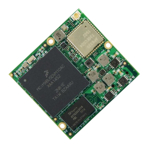
The EDM1-IMX6 is a high performance highly integrated EDM type 1 System-on-Module
designed around the NXP i.MX6 Multicore ARM Cortex-A9. The EDM1-IMX6 provides an
ideal building block that easily integrates with a wide range of target markets requiring rich
multimedia functionality, powerful graphics and video capabilities, as well as high-processing
power, compact, cost effective and with low power consumption.
The EDM1-IMX6 System-on-Module is typically being used as building blocks for portable and stationary
embedded systems. The core CPU and support circuits, including DRAM, booth flash, power sequencing,
CPU power supplies, Gigabit Ethernet and display interfaces are concentrated on the module. The
modules are used with application specific carrier boards that implement other features such as audio
CODECs, touch controllers, sensors and etcetera.
The modular approach offered by the EDM standard gives your project scalability, fast time to market and
upgradability while reducing engineering risk and maintain a competitive total cost of ownership.

EDM1-IMX6 HARDWARE MANUAL –VER 1.00 –NOV 14 2019
Page 8of 80
1.2. General Care and Maintenance
Your device is a product of superior design and craftsmanship and should be treated with care.
The following suggestions will help you.
•Keep the device dry. Precipitation, humidity, and all types of liquids or moisture can contain
minerals that will corrode electronic circuits. If your device does get wet, allow it to dry completely.
•Do not use or store the device in dusty, dirty areas. Its moving parts and electronic components
can be damaged.
•Do not store the device in hot areas. High temperatures can shorten the life of electronic devices,
damage batteries, and warp or melt certain plastics.
•Do not store the device in cold areas. When the device returns to its normal temperature,
moisture can form inside the device and damage electronic circuit boards.
•Do not attempt to open the device.
•Do not drop, knock, or shake the device. Rough handling can break internal circuit boards and
fine mechanics.
•Do not use harsh chemicals, cleaning solvents, or strong detergents to clean the device.
•Do not paint the device. Paint can clog the moving parts and prevent proper operation.
•Unauthorized modifications or attachments could damage the device and may violate regulations
governing radio devices.
These suggestions apply equally to your device, battery, charger, or any enhancement. If any device is
not working properly, take it to the nearest authorized service facility for service.
Regulatory information
Disposal of Waste Equipment by Users in Private Household in the European Union
This symbol on the product or on its packaging indicates that this product must not be
disposed of with your other household waste. Instead, it is your responsibility to dispose
of your waste equipment by handing it over to a designated collection point for the
recycling of waste electrical and electronic equipment. The separate collection and
recycling of your waste equipment at the time of disposal will help to conserve natural
resources and ensure that it is recycled in a manner that protects human health and the
environment. For more information about where you can drop off your waste equipment
for recycling, please contact your local city office, your household waste disposal service or the shop
where you purchased the product.
We hereby declare that the product is in compliance with the essential requirements and
other relevant provisions of European Directive 1999/5/EC (radio equipment and
telecommunications terminal equipment Directive).

EDM1-IMX6 HARDWARE MANUAL –VER 1.00 –NOV 14 2019
Page 9of 80
Federal Communications Commission (FCC) Unintentional emitter per FCC Part 15
This device has been tested and found to comply with the limits for a Class B digital
device, pursuant to Part 15 of the FCC rules. These limits are designed to provide
reasonable protection against harmful interference in a residential installation. This
equipment generates, uses, and can radiate radio frequency energy and, if not
installed and used in accordance with the instructions, may cause harmful interference
to radio or television reception. However, there is no guarantee that interference will
not occur in a particular installation. If this equipment does cause interference to radio and television
reception, which can be determined by turning the equipment off and on, the user is encouraged to try to
correct the interference by one or more of the following measures:
■ Reorient or relocate the receiving antenna
■ Increase the separation between the equipment and receiver
■ Connect the equipment to an outlet on a different circuit from that to which the receiver is connected
■ Consult the dealer or an experienced radio/TV technician for help.
WARNING! To reduce the possibility of heat-related injuries or of overheating the
computer, do not place the computer directly on your lap or obstruct the computer air
vents. Use the computer only on a hard, flat surface. Do not allow another hard surface,
such as an adjoining optional printer, or a soft surface, such as pillows or rugs or
clothing, to block airflow. Also, do not allow the AC adapter to contact the skin or a soft
surface, such as pillows or rugs or clothing, during operation. The computer and the AC
adapter comply with the user-accessible surface temperature limits defined by the International Standard
for Safety of Information Technology Equipment (IEC 60950).

EDM1-IMX6 HARDWARE MANUAL –VER 1.00 –NOV 14 2019
Page 10 of 80
1.3. Block Diagram
Figure 1 - EDM1-IMX6 Block Diagram

EDM1-IMX6 HARDWARE MANUAL –VER 1.00 –NOV 14 2019
Page 11 of 80
1.4. EDM Compatibility
The EDM1-IMX6 is fully compatible with the EDM Type 1 Standard specifications.
For additional details, please refer to the “EDM Standard Specifications”.
Figure 2 –EDM Type 1 Compatibility Chart
Table 1 - EDM Compatibility Overview
Interface
Description
LAN
1 Gigabit Ethernet
LVDS
1 single channel 18/24 bit
HDMI
1 HDMI ver.1.4 compatible
TTL Display
1 TTL 18/24 bit Display
PCIe
1 Lane PCIe 2.0
SATA
1 SATA II
USB Host
1 USB 2.0 Host port
USB OTG
1 USB 2.0 OTG port (possible to use in Host mode)
GPMC
8 bit localbus interface with 4 chip selects
I2S
2 Independent I2S interfaces
SPDIF
1 S/P DIF interface
CAN Bus
2 FlexCAN CAN 2.0B protocol compliant interfaces
UART
2 UART 4 wire
SDIO
1 SDIO interface 4 bit
SPI
2 SPI interfaces with 2 chip selects
I2C
2 independent general purpose interfaces
1 dedicated towards display/system functions
GPIO
10 dedicated GPIO’s available
RTC
On carrierboard

EDM1-IMX6 HARDWARE MANUAL –VER 1.00 –NOV 14 2019
Page 12 of 80
1.5. Dimensional Drawing
The EDM1-IMX6 is an EDM Type 1 Compact Form Factor System-on-Module and follows the EDM
Standard Specifications in regards of dimensions and mounting options.
2D and 3D files can be obtained from the www.technexion.com homepage.
For additional details, please refer to the “EDM Standard Specifications”.
Figure 3 - EDM1-IMX6 Dimensional Drawing

EDM1-IMX6 HARDWARE MANUAL –VER 1.00 –NOV 14 2019
Page 13 of 80
1.6. Component Location
Figure 4 - EDM1-IMX6 Top view
Item
Description
Item
Description
1
NXP i.MX6 Processor
5
Memory IC (2)
2
MMPF0100 Power Management IC
6
MIPI Camera / Display Connector
3
NAND Flash / eMMC (co-layout)
7
WiFi / BT Module
4
JTAG Interface
8
EDM Type 1 Connector
Figure 5 - EDM1-IMX6 Bottom view
Item
Description
Item
Description
1
Atheros AR8035 Gigabit Ethernet PHY
2
Memory IC (2)
1
2
3
4
7
5
6
8
1
2
2
5

EDM1-IMX6 HARDWARE MANUAL –VER 1.00 –NOV 14 2019
Page 14 of 80
2. Core Components
2.1. NXP i.MX6 Cortex-A9 Multi-core Processor
The NXP i.MX6 processor is an implementation of the Single/Dual/Quad/Quadplus ARM Cortex™-A9
core, which operates at frequencies up to 1.2 GHz. The i.MX6 provides a variety of interfaces and
supports the following main features:
•Single / Dual / Quad Core ARM Cortex™-A9. Core configuration is symmetric, where each core
includes:
o32 KByte L1 Instruction Cache
o32 KByte L1 Data Cache
oPrivate Timer and Watchdog
oCortex-A9 NEON MPE (Media Processing Engine) Co-processor
•Level 2 Cache—Unified instruction and data (up to 1 MByte)
•General Interrupt Controller (GIC) with 128 interrupt support
•Global Timer
•Snoop Control Unit (SCU)
•NEON MPE coprocessor:
oSIMD Media Processing Architecture
oNEON register file with 32x64-bit general-purpose registers
oNEON Integer execute pipeline (ALU, Shift, MAC)
oNEON dual, single-precision floating point execute pipeline (FADD, FMUL)
oNEON load/store and permute pipeline
•Integrated Power Management unit:
oTemperature Sensor for monitoring the die temperature
oDVFS techniques for low power modes
oFlexible clock gating control scheme
•Multimedia Hardware Accelerators
Figure 6 –NXP i.MX6 Processor Blocks

EDM1-IMX6 HARDWARE MANUAL –VER 1.00 –NOV 14 2019
Page 15 of 80
Figure 7 –NXP i.MX6 Processor Scalability Overview (Solo/Duallite/Dual/Quad/QuadPlus)

EDM1-IMX6 HARDWARE MANUAL –VER 1.00 –NOV 14 2019
Page 16 of 80
2.1.1. i.MX6 Memory Interfaces
•The memory system consists of the following components:
oLevel 1 Cache—32 KB Instruction, 32 KB Data cache per core
oLevel 2 Cache—Unified instruction and data (1 MByte)
•On-Chip Memory:
oBoot ROM, including HAB (96 KB)
oInternal multimedia / shared, fast access RAM (OCRAM, 256 KB)
oSecure/non-secure RAM (16 KB)
•External memory interfaces:
o16-bit, 32-bit, and 64-bit DDR3-1066 and LV-DDR3-1066
o8-bit NAND-Flash, including support for Raw MLC/SLC, 2 KB, 4 KB, and 8 KB page size,
oBA-NAND, PBA-NAND, LBA-NAND, OneNAND™ and others. BCH ECC up to 32 bit.
2.1.2. i.MX6 DMA Engine
The SDMA is multi-channel flexible DMA engine. It helps in maximizing system performance by off-
loading the various cores in dynamic data routing. It has the following features:
•Powered by a 16-bit Instruction-Set micro-RISC engine
•Multi-channel DMA supporting up to 32 time-division multiplexed DMA channels
•48 events with total flexibility to trigger any combination of channels
•Memory accesses including linear, FIFO, and 2D addressing
•Shared peripherals between ARM and SDMA
•Very fast Context-Switching with 2-level priority based preemptive multi-tasking
•DMA units with auto-flush and prefetch capability
•Flexible address management for DMA transfers (increment, decrement, and no address
changes on source and destination address)
•DMA ports can handle unit-directional and bi-directional flows (copy mode)
•Up to 8-word buffer for configurable burst transfers
•Support of byte-swapping and CRC calculations
•Library of Scripts and API is available

EDM1-IMX6 HARDWARE MANUAL –VER 1.00 –NOV 14 2019
Page 17 of 80
2.1.3. i.MX6 Video and Graphics Subsystems
The EDM1-IMX6 video graphics subsystem consists of the following i.MX6 sub-blocks.
•VPU: A multi-standard high performance video codec engine supporting encode/decode
operations of the following:
oDecoding: H.264 BP/CBP/MP/HP, VC-1 SP/MP/AP, MPEG-4 SP/ASP, H.263 P0/P3,
MPEG-1/2 MP, Divx (Xvid) HP/PP/HTP/HDP, VP8 (1280x720), AVS, H.264-MVC
(1280x720), MJPEG BP (max. 8192x8192) up to full-HD 1920x1088 @30fps plus D1
@30fps.
oEncoding: H.264 BP/CBP, MPEG-4 SP, H.263 P0/P3, MJPEG BP (max. 192x8192) up to
full-HD 1920x1088@30fps.
•GPU2Dv2: Hardware acceleration of 2D graphics (Bit BLT and Stretch BLT). Based on the
Vivante GC320 IP core.
•GPUVG: An OpenVG 1.1 Graphics Processing Unit providing hardware acceleration of vector
graphics. Based on the Vivante GC355 IP core
Additionally the EDM1-IMX6 incorporates the following 3D GPU engine
The EDM1-IMX6 featuring an i.MX6 Solo or Duallite processor:
•GPU3Dv5: A 3D GPU (Vivante GC880), compliant with OpenGL ES2.0, OpenGL ES1.1 and
OpenVG 1.1.
The EDM1-IMX6featuring an i.MX6 Dual or Quad processor:
•GPU3Dv4: A 3D GPU (Vivante GC2000), compliant with OpenGL ES2.0, OpenGL ES1.1 and
OpenVG 1.1.
The EDM1-IMX6 featuring an i.MX6 DualPlus or QuadPlus processor:
•GPU3Dv4: A 3D GPU (Vivante GC2000+), compliant with OpenGL ES2.0, OpenGL ES1.1 and
OpenVG 1.1.

EDM1-IMX6 HARDWARE MANUAL –VER 1.00 –NOV 14 2019
Page 18 of 80
2.2. Power Management IC (MMPF0100)
The EDM1-IMX6 has on onboard NXP MMPF0100 power management integrated circuit (PMIC) that
features a configurable architecture supporting the numerous outputs with various current ratings as well
as programmable voltage and sequencing required by the components on the EDM1-IMX6 module.
Table 2 - PMIC Signal Description
PMIC
PIN
i.MX6
BALL
PAD NAME
Signal
V
I/O
Description
53
R2
GPIO_05
I2C3_SCL
3V3
I/O
I2C bus clock line
54
R4
GPIO_16
I2C3_SDA
3V3
I/O
I2C bus data line
56
D11
PMIC_ON_REQ
PMIC_ON_REQ
3V3
I
PMIC Power ON/OFF Input
from processor
1
U20
PMIC_INT_B
PMIC_INT_B
3V3
I
PMIC Interupt Signal
3
C11
POR_B
POR_B
3V3
I
PMIC Reset Signal
4
F11
PMIC_STBY_REQ
PMIC_STBY_REQ
3V3
I
PMIC Standby Input Signal
For more information, please contact your TechNexion sales representative.

EDM1-IMX6 HARDWARE MANUAL –VER 1.00 –NOV 14 2019
Page 19 of 80
2.3. Memory
The EDM1-IMX6 integrates Double Data Rate III (DDR3) Synchronous DRAM in either a single (32 bit) or
a dual (64 bit) channel configuration.
The following memory chips have been validated and tested on the EDM1-IMX6 System-on-Module:
•SKHynix
•Samsung
•ISSI
•Micron
NOTE : The i.MX6 Solo only support single (32 bit) channel configuration.
For more information, please contact your TechNexion sales representative.

EDM1-IMX6 HARDWARE MANUAL –VER 1.00 –NOV 14 2019
Page 20 of 80
2.4. eMMC Storage
The EDM1-IMX6 can be ordered with onboard eMMC storage in different configurations and capacity.
The onboard eMMC device is connected on the SD3 pins of the i.MX6 processor in a 8 bit width
configuration.
The following eMMC chips have been validated and tested on the EDM1-IMX6 System-on-Module:
•Sandisk iNAND
•Kingston eMMC
•Micron eMMC
For more information, please contact your TechNexion sales representative.
Table 3 - eMMC Signal Description
i.MX6
BALL
PAD NAME
Signal
V
I/O
Description
E14
SD3_DAT0
eMMC_DATA0
3V3
I/O
MMC/SDIO Data bit 0
F14
SD3_DAT1
eMMC_DATA1
3V3
I/O
MMC/SDIO Data bit 1
A15
SD3_DAT2
eMMC_DATA2
3V3
I/O
MMC/SDIO Data bit 2
B15
SD3_DAT3
eMMC_DATA3
3V3
I/O
MMC/SDIO Data bit 3
D13
SD3_DAT4
eMMC_DATA4
3V3
I/O
MMC/SDIO Data bit 4
C13
SD3_DAT5
eMMC_DATA5
3V3
I/O
MMC/SDIO Data bit 5
E13
SD3_DAT6
eMMC_DATA6
3V3
I/O
MMC/SDIO Data bit 6
F13
SD3_DAT7
eMMC_DATA7
3V3
I/O
MMC/SDIO Data bit 7
B13
SD3_CMD
eMMC_CMD
3V3
I/O
MMC/SDIO Command
D14
SD3_CLK
eMMC_CLK
3V3
O
MMC/SDIO Clock
Table of contents
Other TechNexion Control Unit manuals
TechNexion
TechNexion PICO-IMX8M User manual
TechNexion
TechNexion TAM-3517 User manual
TechNexion
TechNexion PICO-IMX6UL-EMMC User manual
TechNexion
TechNexion XORE-WIZARD-IMX8M-MINI User manual
TechNexion
TechNexion PICO-WIZARD-IMX8M-MINI User manual
TechNexion
TechNexion FLEX-IMX8M-Mini User manual

TechNexion
TechNexion PIXI-9377 User manual
TechNexion
TechNexion EDM1-IMX6PLUS User manual
TechNexion
TechNexion PICO-IMX6 User manual
