FISCHER FISCHERSCOPE X-RAY 4000 Series User manual
OPERATOR’S MANUAL
Coating Thickness Material Analysis Microhardness Material Testing
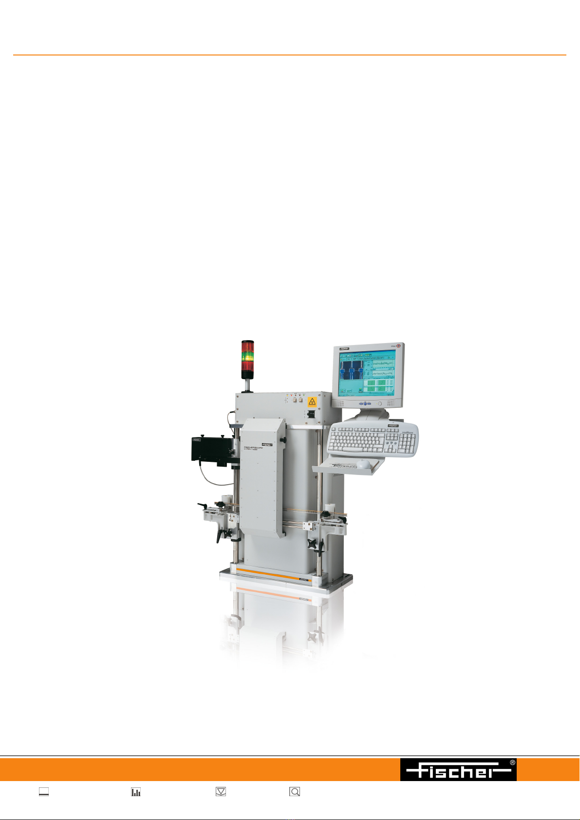
FISCHERSCOPE® X-RAY 4000 Series

Operator’s Manual
FISCHERSCOPE®X-RAY 4000 Series
X-ray fluorescence (EDXRF) measuring system
For coating thickness measurements and materials analysis according to the energy
dispersive X-ray fluorescence method
On our home page www.helmut-fischer.com you will find the addresses of our sole agen-
cies and subsidiary companies around the globe.
© 2012 by Helmut Fischer GmbH Institut für Elektronik und Messtechnik, Germany.
This operator’s manual remains the copyrighted property of Helmut Fischer GmbH. All
rights reserved. This manual may not be reproduced by any means (print, photocopy,
microfilm or any other method) in full or in part, or processed, multiplied or distributed to
third parties by electronic means without the written consent of Helmut Fischer GmbH.
Subject to correction and technical changes.
Document order number: 952-597
Issue date: October 10, 2012
Manufacturer
Helmut Fischer GmbH Phone: +49 (0) 70 31 3 03 - 0
Institut für Elektronik und Messtechnik Fax: +49 (0) 70 31 3 03 - 710
Industriestraße 21 www.helmut-fischer.com
Quality Assurance System of the Helmut Fischer GmbH
DIN EN ISO 9001:2008 Management system certified by Germanischer Lloyd
Systems Certification
DIN ISO/IEC 17025 Calibration lab accredited for certified mass per unit area
standards

FISCHERSCOPE®X-RAY 3
Table of Contents
Table of Contents
1 Safety Information . . . . . . . . . . . . . . . . . . . . . . . . . . . . . . . . . . . . . . . . 7
1.1 Intended Use . . . . . . . . . . . . . . . . . . . . . . . . . . . . . . . . . . . . . . . . . . . . . . . . . . .7
1.2 Safety of the Electrical Equipment. . . . . . . . . . . . . . . . . . . . . . . . . . . . . . . . . . .7
1.3 Maintenance and Repair . . . . . . . . . . . . . . . . . . . . . . . . . . . . . . . . . . . . . . . . . .7
1.4 X-Radiation Safety. . . . . . . . . . . . . . . . . . . . . . . . . . . . . . . . . . . . . . . . . . . . . . .8
1.5 Requirements for the Operating Personnel . . . . . . . . . . . . . . . . . . . . . . . . . . . .9
1.6 X-Radiation Safety Details. . . . . . . . . . . . . . . . . . . . . . . . . . . . . . . . . . . . . . . .10
2 Instrument Overview . . . . . . . . . . . . . . . . . . . . . . . . . . . . . . . . . . . . . 11
2.1 Areas of Application. . . . . . . . . . . . . . . . . . . . . . . . . . . . . . . . . . . . . . . . . . . . .11
2.2 X-Ray Fluorescence . . . . . . . . . . . . . . . . . . . . . . . . . . . . . . . . . . . . . . . . . . . .12
2.3 Functional Principle of the Instrument . . . . . . . . . . . . . . . . . . . . . . . . . . . . . . .13
2.4 Components . . . . . . . . . . . . . . . . . . . . . . . . . . . . . . . . . . . . . . . . . . . . . . . . . .15
3 Switching the Instrument on and off. . . . . . . . . . . . . . . . . . . . . . . . . 19
3.1 Switching on the Instrument . . . . . . . . . . . . . . . . . . . . . . . . . . . . . . . . . . . . . .19
3.2 Switching off the Instrument . . . . . . . . . . . . . . . . . . . . . . . . . . . . . . . . . . . . . .20
3.3 Communication between Instrument and WinFTM. . . . . . . . . . . . . . . . . . . . . .20
4 Manual Measurements . . . . . . . . . . . . . . . . . . . . . . . . . . . . . . . . . . . . 21
4.1 Deleting Measurement Readings. . . . . . . . . . . . . . . . . . . . . . . . . . . . . . . . . . .22
5 WinFTM File Structure . . . . . . . . . . . . . . . . . . . . . . . . . . . . . . . . . . . . 25
5.1 Def.MA . . . . . . . . . . . . . . . . . . . . . . . . . . . . . . . . . . . . . . . . . . . . . . . . . . . . . .26
5.2 Measurement Application . . . . . . . . . . . . . . . . . . . . . . . . . . . . . . . . . . . . . . . .26
5.3 Product . . . . . . . . . . . . . . . . . . . . . . . . . . . . . . . . . . . . . . . . . . . . . . . . . . . . . .26
6 User Interface of the WinFTM Software . . . . . . . . . . . . . . . . . . . . . . 29
6.1 WinFTM Main Window. . . . . . . . . . . . . . . . . . . . . . . . . . . . . . . . . . . . . . . . . . .29
6.2 Video Image . . . . . . . . . . . . . . . . . . . . . . . . . . . . . . . . . . . . . . . . . . . . . . . . . .31
6.3 Statistics Field . . . . . . . . . . . . . . . . . . . . . . . . . . . . . . . . . . . . . . . . . . . . . . . . .33
6.4 Measurement Value Field . . . . . . . . . . . . . . . . . . . . . . . . . . . . . . . . . . . . . . . .33

4FISCHERSCOPE®X-RAY
Table of Contents
6.5 Status Bar . . . . . . . . . . . . . . . . . . . . . . . . . . . . . . . . . . . . . . . . . . . . . . . . . . . .36
6.6 mq Value . . . . . . . . . . . . . . . . . . . . . . . . . . . . . . . . . . . . . . . . . . . . . . . . . . . . .36
6.7 Limited Operating Mode - Short menu. . . . . . . . . . . . . . . . . . . . . . . . . . . . . . .38
6.8 The Spectrum Window . . . . . . . . . . . . . . . . . . . . . . . . . . . . . . . . . . . . . . . . . .39
7 Product Administration . . . . . . . . . . . . . . . . . . . . . . . . . . . . . . . . . . . 45
7.1 Product . . . . . . . . . . . . . . . . . . . . . . . . . . . . . . . . . . . . . . . . . . . . . . . . . . . . . .45
7.2 Setting up a new product. . . . . . . . . . . . . . . . . . . . . . . . . . . . . . . . . . . . . . . . .45
7.3 Importing a product . . . . . . . . . . . . . . . . . . . . . . . . . . . . . . . . . . . . . . . . . . . . .46
7.4 Modifying a product . . . . . . . . . . . . . . . . . . . . . . . . . . . . . . . . . . . . . . . . . . . . .47
7.5 Deleting a product . . . . . . . . . . . . . . . . . . . . . . . . . . . . . . . . . . . . . . . . . . . . . .47
7.6 Assigning a new measurement application to a product . . . . . . . . . . . . . . . . .48
7.7 Modifying a measurement application . . . . . . . . . . . . . . . . . . . . . . . . . . . . . . .48
7.8 Copying a measurement application . . . . . . . . . . . . . . . . . . . . . . . . . . . . . . . .48
7.9 Deleting a measurement application . . . . . . . . . . . . . . . . . . . . . . . . . . . . . . . .49
7.10 Viewing the Def.MA . . . . . . . . . . . . . . . . . . . . . . . . . . . . . . . . . . . . . . . . . . . . .49
7.11 Importing a Def.MA . . . . . . . . . . . . . . . . . . . . . . . . . . . . . . . . . . . . . . . . . . . . .49
7.12 Backing up product or Def.MA files . . . . . . . . . . . . . . . . . . . . . . . . . . . . . . . . .50
7.13 Reference samples . . . . . . . . . . . . . . . . . . . . . . . . . . . . . . . . . . . . . . . . . . . . .50
7.14 Base material in Def.MA . . . . . . . . . . . . . . . . . . . . . . . . . . . . . . . . . . . . . . . . .51
7.15 Monitoring the measurement devices . . . . . . . . . . . . . . . . . . . . . . . . . . . . . . .53
8 Handling of Measurement Data and Statistical Evaluations . . . . . . 55
8.1 Saving / not saving measurement data . . . . . . . . . . . . . . . . . . . . . . . . . . . . . .55
8.2 Overwriting Measurement Data . . . . . . . . . . . . . . . . . . . . . . . . . . . . . . . . . . . .56
8.3 Closing a Block (Order no. / Operator) . . . . . . . . . . . . . . . . . . . . . . . . . . . . . .56
8.4 Block evaluation (statistics) . . . . . . . . . . . . . . . . . . . . . . . . . . . . . . . . . . . . . . .58
8.5 Variable and fixed block size . . . . . . . . . . . . . . . . . . . . . . . . . . . . . . . . . . . . . .59
8.6 Deleting a block. . . . . . . . . . . . . . . . . . . . . . . . . . . . . . . . . . . . . . . . . . . . . . . .59
8.7 Statistics . . . . . . . . . . . . . . . . . . . . . . . . . . . . . . . . . . . . . . . . . . . . . . . . . . . . .60
9 Setting Up the Print Form Using PDM. . . . . . . . . . . . . . . . . . . . . . . . 61
9.1 Statistical Evaluation and Documentation Using the
Supplementary Software PDM. . . . . . . . . . . . . . . . . . . . . . . . . . . . . . . . . . . . .61
9.2 Editing Print Form Templates Using PDM . . . . . . . . . . . . . . . . . . . . . . . . . . . .62
9.3 Inserting Variables for Print Form Templates. . . . . . . . . . . . . . . . . . . . . . . . . .63
9.4 Variables Available for Block Evaluation . . . . . . . . . . . . . . . . . . . . . . . . . . . . .63
9.5 Variables Available for the final Evaluation . . . . . . . . . . . . . . . . . . . . . . . . . . .68

FISCHERSCOPE®X-RAY 5
Table of Contents
9.6 Products with a variable or fixed block size . . . . . . . . . . . . . . . . . . . . . . . . . . .71
9.7 Special Features for SPC Charts. . . . . . . . . . . . . . . . . . . . . . . . . . . . . . . . . . .73
9.8 Printing the Print Form Using the Supplementary Software PDM . . . . . . . . . .74
10 Measurement Uncertainty and Measuring Ranges. . . . . . . . . . . . . . 75
10.1 Meaning of the measurement uncertainty . . . . . . . . . . . . . . . . . . . . . . . . . . . .76
10.2 Random Error . . . . . . . . . . . . . . . . . . . . . . . . . . . . . . . . . . . . . . . . . . . . . . . . .77
10.3 Systematic Error . . . . . . . . . . . . . . . . . . . . . . . . . . . . . . . . . . . . . . . . . . . . . . .78
10.4 Display of the measurement uncertainty . . . . . . . . . . . . . . . . . . . . . . . . . . . . .79
11 Task programming . . . . . . . . . . . . . . . . . . . . . . . . . . . . . . . . . . . . . . . 82
11.1 Starting a Task . . . . . . . . . . . . . . . . . . . . . . . . . . . . . . . . . . . . . . . . . . . . . . . .82
11.2 Programming Tool . . . . . . . . . . . . . . . . . . . . . . . . . . . . . . . . . . . . . . . . . . . . . .82
11.3 Getting started with task programming . . . . . . . . . . . . . . . . . . . . . . . . . . . . . .83
11.4 Syntax of Task Commands . . . . . . . . . . . . . . . . . . . . . . . . . . . . . . . . . . . . . . .83
11.5 List of Task Commands . . . . . . . . . . . . . . . . . . . . . . . . . . . . . . . . . . . . . . . . . .83
11.6 Example Specification Limit Commands . . . . . . . . . . . . . . . . . . . . . . . . . . . . .86
12 Data back-up. . . . . . . . . . . . . . . . . . . . . . . . . . . . . . . . . . . . . . . . . . . . 87
12.1 Extent of the data back-up. . . . . . . . . . . . . . . . . . . . . . . . . . . . . . . . . . . . . . . .87
12.2 Target path for data back-up . . . . . . . . . . . . . . . . . . . . . . . . . . . . . . . . . . . . . .87
12.3 Back-up cycle . . . . . . . . . . . . . . . . . . . . . . . . . . . . . . . . . . . . . . . . . . . . . . . . .88
13 Mass per unit area and geometric coating thickness . . . . . . . . . . . 90
13.1 Correlation between mass per unit area and coating thickness . . . . . . . . . . . .92
13.2 Calibration standards from FISCHER . . . . . . . . . . . . . . . . . . . . . . . . . . . . . . .94
13.3 Setting the density in the Def.MA . . . . . . . . . . . . . . . . . . . . . . . . . . . . . . . . . .94
14 Measurement device monitoring for the Fischerscope X-RAY . . . . 96
14.1 Calibration of X-ray fluorescence measuring instruments . . . . . . . . . . . . . . . .96
14.2 Why monitor measurement devices? . . . . . . . . . . . . . . . . . . . . . . . . . . . . . . . .98
14.3 Variation of measurement readings . . . . . . . . . . . . . . . . . . . . . . . . . . . . . . . . .99
14.4 Trueness of measurement readings . . . . . . . . . . . . . . . . . . . . . . . . . . . . . . .100
14.5 Random and systematic deviations . . . . . . . . . . . . . . . . . . . . . . . . . . . . . . . .101
14.6 Trueness and precision . . . . . . . . . . . . . . . . . . . . . . . . . . . . . . . . . . . . . . . . .103

6FISCHERSCOPE®X-RAY
Table of Contents
14.7 Practical monitoring of the measurement devices . . . . . . . . . . . . . . . . . . . . .105
14.8 When and how to carry out corrections? . . . . . . . . . . . . . . . . . . . . . . . . . . . .107
14.9 Wouldn’t it be better to re-calibrate? . . . . . . . . . . . . . . . . . . . . . . . . . . . . . . .109
14.10 Pre-run for determining the control limits . . . . . . . . . . . . . . . . . . . . . . . . . . . .110
14.11 Long-term monitoring. . . . . . . . . . . . . . . . . . . . . . . . . . . . . . . . . . . . . . . . . . .115
15 Calibration. . . . . . . . . . . . . . . . . . . . . . . . . . . . . . . . . . . . . . . . . . . . . 117
16 Measurement Data Export . . . . . . . . . . . . . . . . . . . . . . . . . . . . . . . . 123
16.1 Starting the Measurement Data Export . . . . . . . . . . . . . . . . . . . . . . . . . . . . .123
16.2 Export Settings . . . . . . . . . . . . . . . . . . . . . . . . . . . . . . . . . . . . . . . . . . . . . . .124
16.3 Setting up an Export Template . . . . . . . . . . . . . . . . . . . . . . . . . . . . . . . . . . .126
17 Addendum. . . . . . . . . . . . . . . . . . . . . . . . . . . . . . . . . . . . . . . . . . . . . 131
17.1 Description of the Characteristic Statistical Parameters. . . . . . . . . . . . . . . . .131
17.2 Periodic Table of the Elements with X-Ray Properties. . . . . . . . . . . . . . . . . .139
Data Sheet . . . . . . . . . . . . . . . . . . . . . . . . . . . . . . . . . . . . . . . . . . . . . . . . . .141
WinFTM Features . . . . . . . . . . . . . . . . . . . . . . . . . . . . . . . . . . . . . . . . . . . . .145
Index . . . . . . . . . . . . . . . . . . . . . . . . . . . . . . . . . . . . . . . . . . . . . . . . . . . I

FISCHERSCOPE®X-RAY 7
Intended Use Safety Information
1 Safety Information
When used as intended, the FISCHERSCOPE®X-RAY is safe in its operation. When you
use the instrument as intended and observe the safety information, the instrument does
not pose any risks.
Please read and follow these instructions and observe the safety information. Please also
note the generally applicable regulations concerning safety and accident prevention.
1.1 Intended Use
The FISCHERSCOPE X-RAY is used for coating thicknesses measurements and for
materials analysis. The measurement method conforms to DIN 50 987, ASTM B568 and
EN ISO 3497.
The specifications of the instrument and of the accessories are described in the data sheet
in the Attachment to this Operators Manual.
Only accessories recommended and approved by FISCHER may be connected to this
instrument.
Modifications, repairs, maintenance and service work on the FISCHERSCOPE X-RAY and
its accessories must be performed by authorized FISCHER service personnel only.
There is no other intended use. The risk for damage from unintended use lies solely with
the user.
1.2 Safety of the Electrical Equipment
The FISCHERSCOPE X-RAY is designed as a Protection Class I instrument according to
the IEC 348 / VDE 0411 standard. The instrument contains components under line voltage
and under high voltage. Observe the directives and standards IEC 348, VDE 0411.
1.3 Maintenance and Repair
Repair, maintenance and service work on the FISCHERSCOPE X-RAY and its accesso-
ries must be performed by authorized FISCHER service personnel only.
Exceptions are described in the operator’s manual, as replacing the line fuse.

8FISCHERSCOPE®X-RAY
Safety Information X-Radiation Safety
1.4 X-Radiation Safety
The design as a fully protected instrument and the functions of several integrated protec-
tive devices protects the operating personnel and the surroundings fully from x-radiation.
Two devices that work independent of each other ensure that x-radiation can be generated
only when the measurement chamber is closed. For the safe operation of the instrument
please also note the intended use; ref. Chap. 1.1. on Page 7.
Observe the laws and regulations of the country where the FISCHERSCOPE X-RAY
is operated. The responsible government authority must possibly be informed or
consulted about the commissioning of the FISCHERSCOPE X-RAY.
In addition, we would like to point out the following:
Operate the instrument according to the instructions in this manual and the online help.
Do not attempt any structural alterations on the instrument.
Maintenance and service work on the instrument may be performed only by FISCHER
or by companies authorized by FISCHER for this purpose.
1.4.1 Repeat Inspection
FISCHER recommends to check the instrument by an expert in intervals of no longer than
five years. Observe the laws and regulations of the country where the instrument is oper-
ated.
If you prefer to perform the repeat inspection yourself, contact the responsible authority
for the expert responsible for your area.
During the repeat inspection, the expert must be provided with the Certificate of Approval.
Store the Certificate of Approval in a manner that it will be available at the time of the
inspection.
The responsible authority must be notified of the result of the repeat inspection without
being requested to do so.
1.4.2 Safety Devices
Safety devices are absolutely necessary to protect the operating personnel and the
surroundings fully from x-radiation. Two micro switches observe the opening condition of
the protective hood. If the protective hood is opened, the x-ray escape will be closed
(shutter closed).

FISCHERSCOPE®X-RAY 9
Requirements for the Operating Personnel Safety Information
No Alterations to the Instrument!
Only specialized service personnel, as a rule the Service of FISCHER, is authorized to
carry out alterations to the measuring instrument.
1.5 Requirements for the Operating Personnel
1.5.1 Operators with Introductory Training
Operators with introductory training can work with the instrument efficiently and safely.
For this purpose, the instrument is prepared such that all settings for the measuring appli-
cation are made by trained specialists. Then, the software’s scope of functions is
restricted such that only the functions required for carrying out the measuring application
remain accessible (Short menu). This provides operators with introductory training with a
clear workspace and the instrument is protected from interventions and changes in the
software.
Operators with introductory training should have the following knowledge:
Fundamental knowledge about the use of Microsoft®Windows®
Knowledge of the safety information described in this manual
Operators with introductory training must be instructed in the proper use by a person that
has the requisite qualifications.
1.5.2 Trained Specialists
Trained specialists can utilize the full bandwidth of the technical capabilities of the
FISCHERSCOPE X-RAY.
In addition, trained specialists have the following knowledge:
Knowledge of the physical principle of x-ray fluorescence and of the functional prin-
ciple of the FISCHERSCOPE X-RAY instrument
The aforementioned physics knowledge is important for defining the measuring application
and for other settings. Only the most important facts are explained in this
Operators Manual. This does not replace detailed training.
The practice-oriented seminars of FISCHER are a worthwhile opportunity for obtaining the
required knowledge. Several times a year, user seminars that provide insights into the
physical fundamentals of x-ray fluorescence and prepare users for their work with the
measuring instruments are conducted at various locations.
Seminar dates can be found on our website www.helmut-fischer.com.
DANGER
X-radiation and high voltage
Carrying out alterations to the instrument can lead to death or serious inju-
ries and legal consequences.
Do not carry out any alterations to the instrument.
10 FISCHERSCOPE®X-RAY
Safety Information X-Radiation Safety Details
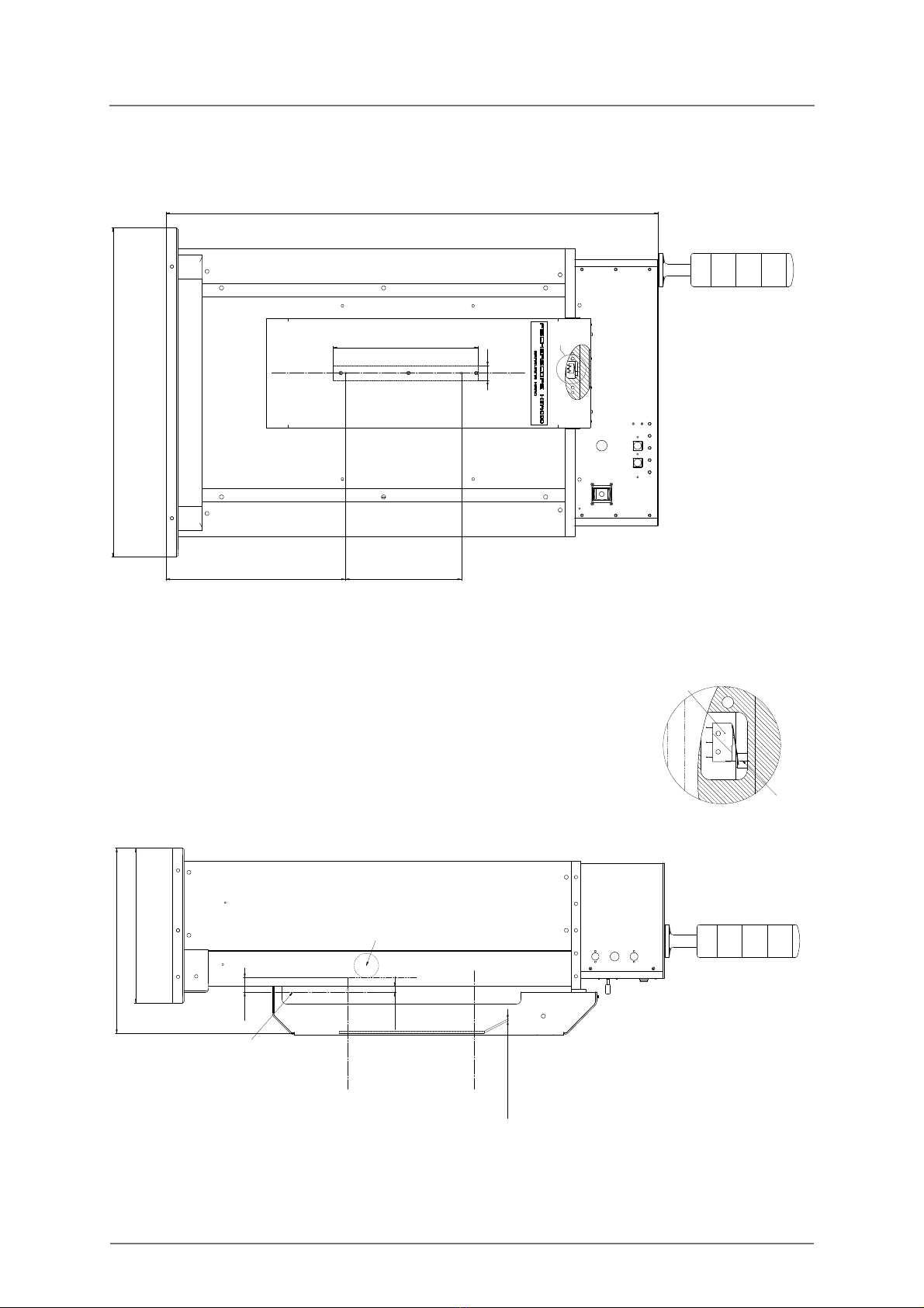
1.6 X-Radiation Safety Details
+RPH3RVLWLRQ
7UDYHO=$[LV
=
PPPHWDOVKHHW
3&7XEH
;5D\%HDP
$[LV
PHVXULQJSODQH
;5D\
6RXUFH3ODQH
;5D\%HDP
$[LV
]D[LVPLQ
]D[LVPD[
=
0LFURVZLWFKHV
$FWXDWLQJ3LQ

FISCHERSCOPE®X-RAY 11
Areas of Application Instrument Overview
2 Instrument Overview
The FISCHERSCOPE®X-RAY is a high performance energy dispersive x-ray fluores-
cence (EDXRF) spectrometer.
The WinFTM®(Fischer Thickness Management Software for Windows®) software
controls the instrument and handles the evaluation of the signals supplied by the
instrument.
The measured values (coating thickness, material compositions, mass per unit area) are
stored and displayed on the monitor. Using WinFTM, you can conveniently design the
measurement results as a print form for printout and export them to other applications.
WinFTM runs under Windows®.
2.1 Areas of Application
The instrument is suited for the following measurement applications:
Analysis of solid materials
Measurement of the composition and coating thicknesses of complex multi-layered
systems
Continuous in-line measurement in production processes
12 FISCHERSCOPE®X-RAY
Instrument Overview X-Ray Fluorescence
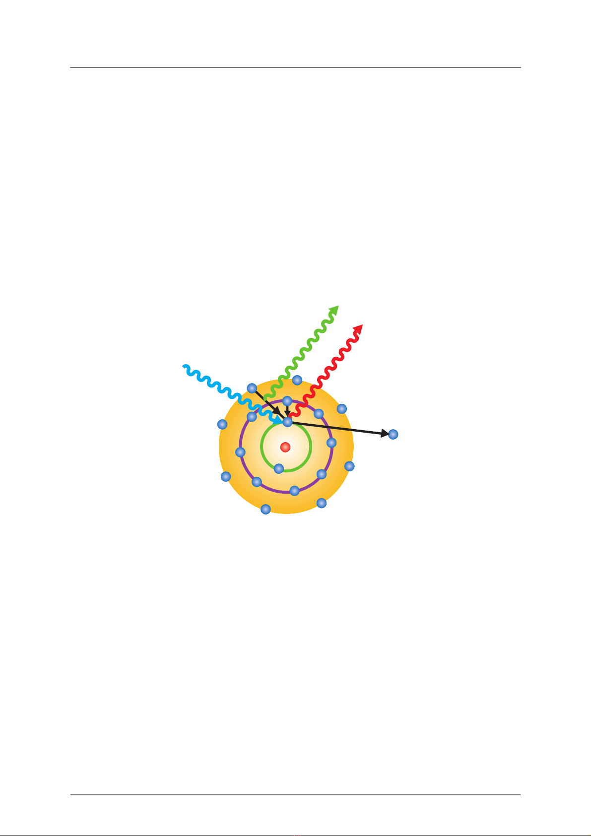
2.2 X-Ray Fluorescence
The specimen is excited with the primary x-radiation. In the process electrons from the
inner electron shells are knocked. Electrons from outer electron shells fill the resultant
voids emitting a fluorescence radiation that is characteristic in its energy distribution for a
particular material. This fluorescence radiation is evaluated by the detector.
The generation of the x-ray fluorescence radiation is shown simplified in Fig. 2-1. One
electron from the K shell is knocked. The resultant void is filled by either an electron from
the L shell or an electron from the M shell. In the process the Kand Kradiation is
generated, which is characteristic for the particular material.
Fig. 2-1: Generation of the x-ray fluorescence radiation
Primary X-radiation
X-ray fluorescence radiation
Shell K
L
M
K
K
Electron
FISCHERSCOPE®X-RAY 13
Functional Principle of the Instrument Instrument Overview
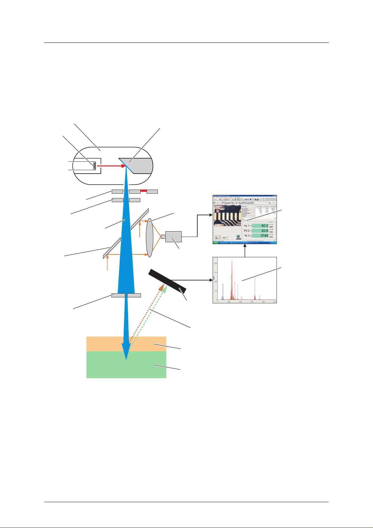
2.3 Functional Principle of the Instrument
The following figure shows the principle structure of the instrument:
Fig. 2-2: Functional principle of the instrument
Functional principle
1. The x-ray tube generates the primary x-radiation (primary radiation). The electrically
heated cathode emits electrons. Accelerated by the applied high voltage to very high
speeds, the electrons bombard the anode material. This generates the primary
x-radiation.
2. The primary filter optimizes the energy distribution of the primary x-radiation.
3. The shutter serves as a safety device and closes the access of the primary x-radiation
to the measurement chamber, if needed.
X-ray tube
Cathode Anode
Primary x-radiation
Mirror
Lens
Video camera
Aperture
Coating layer
Base material
X-ray fluorescence radiation
Spectrum
WinFTM
main window
Detector
Shutter
Primary filter

14 FISCHERSCOPE®X-RAY
Instrument Overview Functional Principle of the Instrument
4. A light source (not shown in Fig. 2-2) illuminates the sample. A mirror and lens direct
the image of the measurement location to a color video camera. The mirror has a hole
in its center for the primary radiation to pass through.
5. The aperture (collimator) limits the cross-section of the primary beam in order to excite
a measurement spot of a defined size.
6. The primary x-radiation impacts the atoms on the sample surface (coating layer and
base material) and in the process knocks electrons from the inner electron shell.
Electrons from outer electron shells fill the resultant voids emitting a fluorescence
radiation that is characteristic in its energy distribution for a particular material.
7. The energy dispersive detector measures the energy distribution of the fluorescence
radiation. A multistage electronics circuit processes the measurement signals.
8. The measured spectrum shows lines or peaks that are characteristic for the chemical
elements in the sample.
9. The WinFTM Software computes the thickness of the coating(s) and/or the analysis
result. The video image of the sample is shown in the WinFTM window. The precise
position of the measurement location and the measurement spot is possible due to the
special design of the optical and the x-ray guidance systems.

FISCHERSCOPE®X-RAY 15
Components
2.4 Components
2.4.1 Aperture (Collimator)
The aperture is used to limit the size of the primary x-ray beam to a defined diameter or
cross-section.
The aperture is a borehole with defined geometries (rectangular or round) and sizes,
through which part of the primary x-ray beam passes. Thus, a fraction of the primary radi-
ation is suppressed.
A reproducible, controlled and defined primary x-ray beam geometry is an important
prerequisite for good measurement accuracy.
To create ideal excitation conditions for every measurement, the instrument is equipped
with several electrically changeable apertures, see the Technical Data Sheet in the
addendum of this document. Using the software, you can select the optimum aperture for
the respective measurement application.
To select the aperture:
1. In the WinFTM main window select Product > Modify….
The window Modify product appears.
2. Select the tab Application.
3. Click Collim..
4. Select the collimator and click OK.
2.4.2 Shutter
The shutter is used to keep the primary x-rays from entering the measurement chamber
and the environment.
The shutter is part of the safety system. The shutter closes immediately, when a malfunc-
tion occurs. X-rays can then no longer reach the measurement chamber and the environ-
ment.
2.4.3 Specimen Lighting
The specimen lighting ensures good visibility of the specimen in the video window. The
lighting elements are white LEDs that are located in the area of the aperture.
Use the slide control in the video window to adjust the intensity of the illumination.
16 FISCHERSCOPE®X-RAY
Components
2.4.4 Primary filter (Optional)
The primary filter consists of a thin foil made of nickel or aluminum, which is located
between the x-ray tube and the specimen to be measured.
By using a primary filter, the composition of the primary X-radiation can be influenced such
that it is optimally suited for the excitation of the respective specimen for x-ray fluores-
cence. Thus, undesirable components of the fluorescence spectrum can be avoided from
the outset.
Using a primary filter is useful for certain applications, however, it is not required in most
cases. The user requires special physical knowledge for a case-by-case evaluation of this
question.
The primary filter can be controlled using the software, if the WinFTM extension SUPER
is installed.
To change the primary filter:
1. In the WinFTM main window select Product > Modify….
The window Modify product appears.
2. Select the tab Application.
3. Click Def.MA (local).
The window Definition of measuring conditions… appears.
4. In the upper right field select the desired primary filter and click OK.
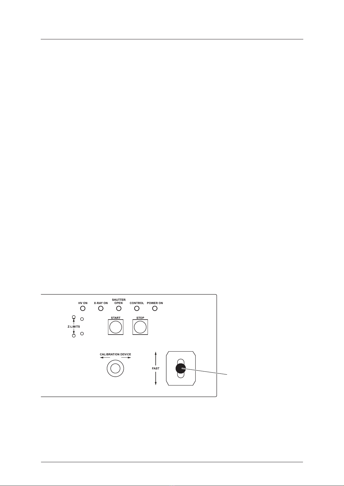
2.4.5 Control Panel
You can use the control panel to control certain functions of the instrument.
Fig. 2-3: Control panel of the instrument
Joystick

FISCHERSCOPE®X-RAY 17
Components
Table 2-1: Function of the operating controls
Operating control Function
Joystick Controls the measuring stage movement.
START Starts a single measurement.
STOP Stops a measurement.
Table 2-2: Function of the LEDs
LED Function
HV ON Lights yellow when the high voltage is turned on.
X-RAY ON Lights red when the X-radiation is ready.
SHUTTER OPEN Lights yellow when a measurement is in progress.
CONTROL Flashes red when the safety system discovers an error or when
the cover is not fully closed, measurements are not possible.
No malfunction message of the safety system is present if the
LED does not light.
POWER ON Lights green when the instrument is switched on.

18 FISCHERSCOPE®X-RAY
Components
FISCHERSCOPE®X-RAY 19
Switching on the Instrument Switching the Instrument on and off
3 Switching the Instrument on and off
3.1 Switching on the Instrument
The following section describes how to switch on the X-RAY measuring head and the PC.
Always pay attention to this section, when you need to switch on the measuring head, e.g.
after an emergency shut-off.
To switch on the instrument and the PC
1. Switch on the instrument by using the Off/On rocker switch at the rear of the instru-
ment.
2. Plug the FISIM (Fischer Software Identification Module) into an USB port of the
computer.
3. Switch on the PC and the monitor.
Windows will be started.
4. Wait for at least 2 minutes.
The sensor located in the instrument needs this time to reach its operating
temperature.
5. To start WinFTM, double click the WinFTM icon .
6. In the WinFTM start window click OK.
The software will open in the ready-to-measure mode (Communication on). The
product that had been selected prior to powering off will be called automatically.
What you can do next
You can now perform measurements.
CAUTION
Wrong measurement readings
If you don‘t follow the steps described in the following section, the measurement
readings may be wrong.
Follow the steps described below when switching on the measuring head.
The following activities must not be performed immediately after power up, but
only after about half an hour of measuring time:
Calibration and normalization
Monitoring measurement devices including corrective measures

20 FISCHERSCOPE®X-RAY
Switching the Instrument on and off Switching off the Instrument
3.2 Switching off the Instrument
To switch off the instrument and the PC
1. Switch off the instrument by using the Off/On rocker switch at the rear of the instru-
ment.
2. To terminate WinFTM, select File > Exit.
3. To shut down the PC, select Start > Shut down.
4. Switch off the monitor and the printer, if present.
3.3 Communication between Instrument and WinFTM
Communication between instrument and WinFTM is necessary to obtain measurements
with the instrument.
Determining the current communication condition
If the communication is enabled, the measurement distance appears in the status bar.
If the communication is disabled, XRAY Communication OFF appears in the status
bar of the WinFTM window.
It is not possible to make measurements when the communication is disabled, that is,
when WinFTM is in demo mode.
To enable the communication
In the WinFTM main window select General > Communication ON.
To disable the communication
In the WinFTM main window select General > Communication OFF.
Table of contents
Other FISCHER Analytical Instrument manuals


