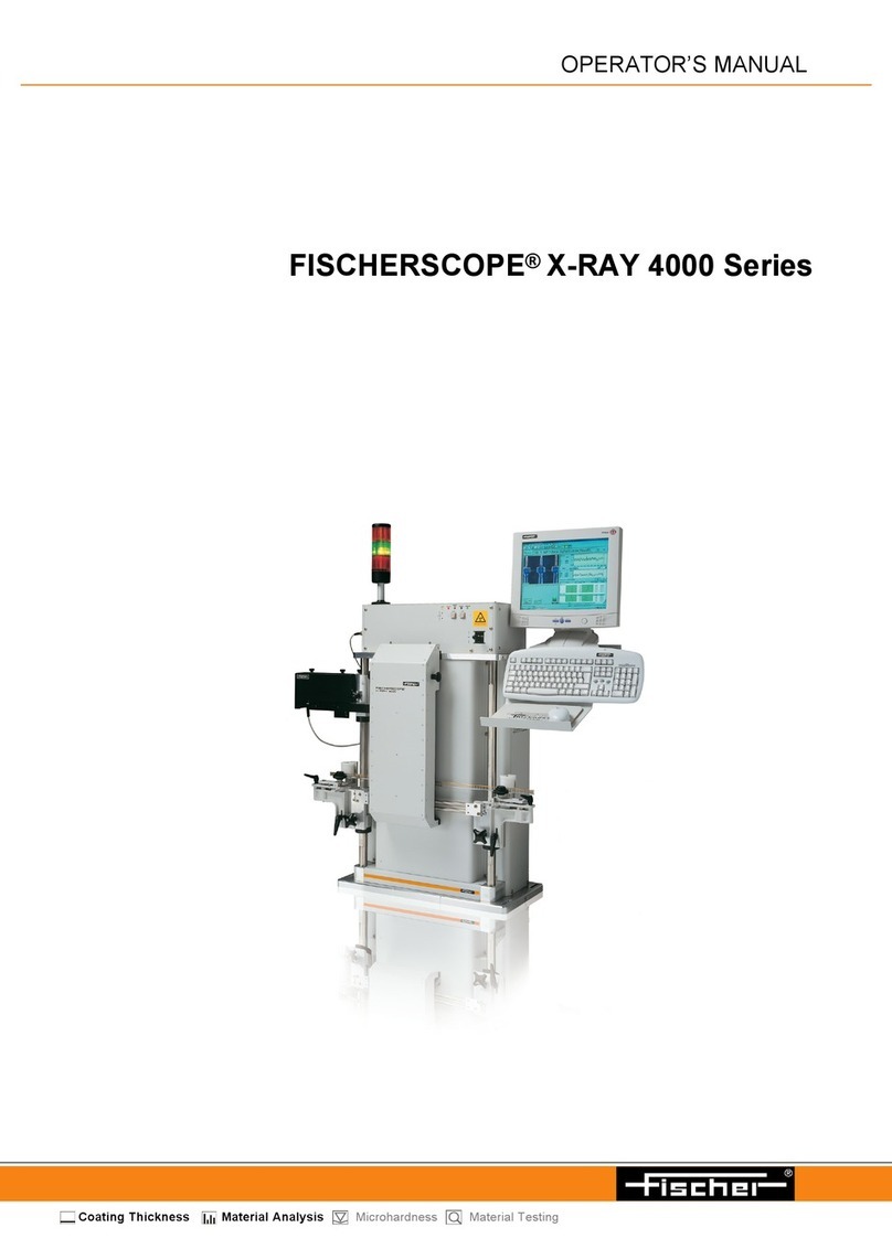
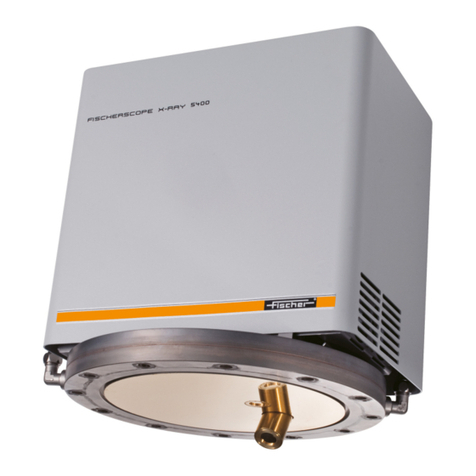
FISCHER FISCHERSCOPE X-RAY XDLM 231 User manual

Operator’s Manual
Coating Thickness Material Analysis Microhardness Material Testing
FISCHERSCOPE® X-RAY XDLM®231
FISCHERSCOPE® X-RAY XDLM®232
FISCHERSCOPE® X-RAY XDLM®237

Operator’s Manual
FISCHERSCOPE®X-RAY XDLM®231
FISCHERSCOPE®X-RAY XDLM®232
FISCHERSCOPE®X-RAY XDLM®237
X-ray fluorescence (EDXRF) measuring instrument
For coating thickness measurements and materials analysis according to the energy dispersive X-
ray fluorescence method
On our home page www.helmut-fischer.com you will find the addresses of our sole agencies and
subsidiary companies around the globe.
© 2015 by Helmut Fischer GmbH Institut für Elektronik und Messtechnik, Germany.
This operator’s manual remains the copyrighted property of Helmut Fischer GmbH. All rights
reserved. This manual may not be reproduced by any means (print, photocopy, microfilm or any
other method) in full or in part, or processed, multiplied or distributed to third parties by electronic
means without the written consent of Helmut Fischer GmbH.
Subject to correction and technical changes.
Document order number: 952-573
Issue date: February 11, 2015
Manufacturer
Helmut Fischer GmbH Phone: +49 (0) 70 31 3 03 - 0
Institut für Elektronik und Messtechnik Fax: +49 (0) 70 31 3 03 - 710
Industriestraße 21 www.helmut-fischer.com
Quality Assurance System of the Helmut Fischer GmbH
DIN EN ISO 9001:2008 Management system certified by Germanischer Lloyd Systems
Certification
DIN ISO/IEC 17025 Calibration lab accredited for certified mass per unit area
standards

FISCHERSCOPE®X-RAY 1
Table of Contents
Table of Contents
1 Safety Information . . . . . . . . . . . . . . . . . . . . . . . . . . . . . . . . . . . . . . . . . . . . . . . 7
1.1 Warning notices used . . . . . . . . . . . . . . . . . . . . . . . . . . . . . . . . . . . . . . . . . 7
1.2 Intended Use . . . . . . . . . . . . . . . . . . . . . . . . . . . . . . . . . . . . . . . . . . . . . . . 7
1.3 Safety of the Electrical Equipment . . . . . . . . . . . . . . . . . . . . . . . . . . . . . . . . . 8
1.4 Maintenance and Repair . . . . . . . . . . . . . . . . . . . . . . . . . . . . . . . . . . . . . . . 8
1.5 X-Radiation Safety . . . . . . . . . . . . . . . . . . . . . . . . . . . . . . . . . . . . . . . . . . . . 8
1.6 Requirements for the Operating Personnel . . . . . . . . . . . . . . . . . . . . . . . . . . 10
1.7 Frequently Asked Questions Concerning X-Radiation Safety . . . . . . . . . . . . . . 11
2 Instrument Overview. . . . . . . . . . . . . . . . . . . . . . . . . . . . . . . . . . . . . . . . . . . . . 13
2.1 Areas of Application . . . . . . . . . . . . . . . . . . . . . . . . . . . . . . . . . . . . . . . . . 13
2.2 Standard-free Measurements . . . . . . . . . . . . . . . . . . . . . . . . . . . . . . . . . . . 13
2.3 X-Ray Fluorescence . . . . . . . . . . . . . . . . . . . . . . . . . . . . . . . . . . . . . . . . . . 14
2.4 Functional Principle of the Instrument . . . . . . . . . . . . . . . . . . . . . . . . . . . . . . 15
2.5 Components . . . . . . . . . . . . . . . . . . . . . . . . . . . . . . . . . . . . . . . . . . . . . . . 17
3 Set up . . . . . . . . . . . . . . . . . . . . . . . . . . . . . . . . . . . . . . . . . . . . . . . . . . . . . . . 21
3.1 Set-up Location . . . . . . . . . . . . . . . . . . . . . . . . . . . . . . . . . . . . . . . . . . . . . 21
3.2 Unpacking the Measuring System . . . . . . . . . . . . . . . . . . . . . . . . . . . . . . . . 22
3.3 Removing the Shipping Lock. . . . . . . . . . . . . . . . . . . . . . . . . . . . . . . . . . . . 22
3.4 Establishing Connections . . . . . . . . . . . . . . . . . . . . . . . . . . . . . . . . . . . . . . 24
3.5 Switching on the Instrument . . . . . . . . . . . . . . . . . . . . . . . . . . . . . . . . . . . . 26
3.6 Switching off the Instrument . . . . . . . . . . . . . . . . . . . . . . . . . . . . . . . . . . . . 27
3.7 Communication between Instrument and WinFTM. . . . . . . . . . . . . . . . . . . . . 27
4 Performing Measurements. . . . . . . . . . . . . . . . . . . . . . . . . . . . . . . . . . . . . . . . . 29
4.1 Deleting Measurement Readings . . . . . . . . . . . . . . . . . . . . . . . . . . . . . . . . . 30
5 WinFTM File Structure . . . . . . . . . . . . . . . . . . . . . . . . . . . . . . . . . . . . . . . . . . . . 31
5.1 Def.MA . . . . . . . . . . . . . . . . . . . . . . . . . . . . . . . . . . . . . . . . . . . . . . . . . . 32
5.2 Measurement Application. . . . . . . . . . . . . . . . . . . . . . . . . . . . . . . . . . . . . . 32
5.3 Product . . . . . . . . . . . . . . . . . . . . . . . . . . . . . . . . . . . . . . . . . . . . . . . . . . 32
6 User Interface of the WinFTM Software . . . . . . . . . . . . . . . . . . . . . . . . . . . . . . . 35
6.1 WinFTM Main Window. . . . . . . . . . . . . . . . . . . . . . . . . . . . . . . . . . . . . . . 35
6.2 Video Image. . . . . . . . . . . . . . . . . . . . . . . . . . . . . . . . . . . . . . . . . . . . . . . 37
6.3 Statistics Field . . . . . . . . . . . . . . . . . . . . . . . . . . . . . . . . . . . . . . . . . . . . . . 39

2 FISCHERSCOPE®X-RAY
Table of Contents
6.4 Measurement Value Field . . . . . . . . . . . . . . . . . . . . . . . . . . . . . . . . . . . . . . 39
6.5 Status Bar. . . . . . . . . . . . . . . . . . . . . . . . . . . . . . . . . . . . . . . . . . . . . . . . . 42
6.6 mq Value . . . . . . . . . . . . . . . . . . . . . . . . . . . . . . . . . . . . . . . . . . . . . . . . . 43
6.7 Limited Operating Mode - Short menu . . . . . . . . . . . . . . . . . . . . . . . . . . . . . 44
6.8 The Spectrum Window. . . . . . . . . . . . . . . . . . . . . . . . . . . . . . . . . . . . . . . . 45
7 Position Specimen . . . . . . . . . . . . . . . . . . . . . . . . . . . . . . . . . . . . . . . . . . . . . . . 51
7.1 Flat Specimens . . . . . . . . . . . . . . . . . . . . . . . . . . . . . . . . . . . . . . . . . . . . . 51
7.2 Cylindrical or Curved Specimens . . . . . . . . . . . . . . . . . . . . . . . . . . . . . . . . 51
7.3 Measurements in Recesses . . . . . . . . . . . . . . . . . . . . . . . . . . . . . . . . . . . . . 52
7.4 Measurements on Inclines. . . . . . . . . . . . . . . . . . . . . . . . . . . . . . . . . . . . . . 52
7.5 Positioning of Specimen . . . . . . . . . . . . . . . . . . . . . . . . . . . . . . . . . . . . . . . 53
7.6 Position the Specimen by Using the Mouse (XDLM 237). . . . . . . . . . . . . . . . . 54
8 Product Administration . . . . . . . . . . . . . . . . . . . . . . . . . . . . . . . . . . . . . . . . . . . 55
8.1 Product . . . . . . . . . . . . . . . . . . . . . . . . . . . . . . . . . . . . . . . . . . . . . . . . . . 55
8.2 Setting up a new product . . . . . . . . . . . . . . . . . . . . . . . . . . . . . . . . . . . . . . 55
8.3 Importing a product. . . . . . . . . . . . . . . . . . . . . . . . . . . . . . . . . . . . . . . . . . 56
8.4 Modifying a product . . . . . . . . . . . . . . . . . . . . . . . . . . . . . . . . . . . . . . . . . 57
8.5 Deleting a product. . . . . . . . . . . . . . . . . . . . . . . . . . . . . . . . . . . . . . . . . . . 57
8.6 Assigning a new measurement application to a product . . . . . . . . . . . . . . . . 58
8.7 Modifying a measurement application . . . . . . . . . . . . . . . . . . . . . . . . . . . . . 58
8.8 Copying a measurement application . . . . . . . . . . . . . . . . . . . . . . . . . . . . . . 58
8.9 Deleting a measurement application . . . . . . . . . . . . . . . . . . . . . . . . . . . . . . 59
8.10 Viewing the Def.MA . . . . . . . . . . . . . . . . . . . . . . . . . . . . . . . . . . . . . . . . . 59
8.11 Importing a Def.MA. . . . . . . . . . . . . . . . . . . . . . . . . . . . . . . . . . . . . . . . . . 59
8.12 Backing up product or Def.MA files. . . . . . . . . . . . . . . . . . . . . . . . . . . . . . . 60
8.13 Reference samples. . . . . . . . . . . . . . . . . . . . . . . . . . . . . . . . . . . . . . . . . . . 60
8.14 Base material in Def.MA . . . . . . . . . . . . . . . . . . . . . . . . . . . . . . . . . . . . . . 61
8.15 Monitoring the measurement devices . . . . . . . . . . . . . . . . . . . . . . . . . . . . . . 63
9 Handling of Measurement Data and Statistical Evaluations. . . . . . . . . . . . . . . . . 65
9.1 Saving / not saving measurement data . . . . . . . . . . . . . . . . . . . . . . . . . . . . 65
9.2 Overwriting Measurement Data . . . . . . . . . . . . . . . . . . . . . . . . . . . . . . . . . 66
9.3 Closing a Block (Order no. / Operator) . . . . . . . . . . . . . . . . . . . . . . . . . . . 66
9.4 Block evaluation (statistics) . . . . . . . . . . . . . . . . . . . . . . . . . . . . . . . . . . . . . 68
9.5 Variable and fixed block size . . . . . . . . . . . . . . . . . . . . . . . . . . . . . . . . . . . 69
9.6 Deleting a block . . . . . . . . . . . . . . . . . . . . . . . . . . . . . . . . . . . . . . . . . . . . 69
9.7 Statistics. . . . . . . . . . . . . . . . . . . . . . . . . . . . . . . . . . . . . . . . . . . . . . . . . . 70

FISCHERSCOPE®X-RAY 3
Table of Contents
10 Setting Up the Print Form Using PDM. . . . . . . . . . . . . . . . . . . . . . . . . . . . . . . . . 71
10.1 Statistical Evaluation and Documentation Using the
Supplementary Software PDM . . . . . . . . . . . . . . . . . . . . . . . . . . . . . . . . . . 71
10.2 Editing Print Form Templates Using PDM . . . . . . . . . . . . . . . . . . . . . . . . . . . 72
10.3 Inserting Variables for Print Form Templates . . . . . . . . . . . . . . . . . . . . . . . . . 73
10.4 Variables Available for Block Evaluation . . . . . . . . . . . . . . . . . . . . . . . . . . . 73
10.5 Variables Available for the final Evaluation . . . . . . . . . . . . . . . . . . . . . . . . . 78
10.6 Products with a variable or fixed block size . . . . . . . . . . . . . . . . . . . . . . . . . 81
10.7 Special Features for SPC Charts . . . . . . . . . . . . . . . . . . . . . . . . . . . . . . . . . 83
10.8 Printing the Print Form Using the Supplementary Software PDM . . . . . . . . . . . 84
11 Measurement Uncertainty and Measuring Ranges . . . . . . . . . . . . . . . . . . . . . . . 85
11.1 Meaning of the measurement uncertainty. . . . . . . . . . . . . . . . . . . . . . . . . . . 86
11.2 Random Error . . . . . . . . . . . . . . . . . . . . . . . . . . . . . . . . . . . . . . . . . . . . . . 87
11.3 Systematic Error . . . . . . . . . . . . . . . . . . . . . . . . . . . . . . . . . . . . . . . . . . . . 88
11.4 Display of the measurement uncertainty . . . . . . . . . . . . . . . . . . . . . . . . . . . . 89
12 Task programming . . . . . . . . . . . . . . . . . . . . . . . . . . . . . . . . . . . . . . . . . . . . . . 92
12.1 Starting a Task . . . . . . . . . . . . . . . . . . . . . . . . . . . . . . . . . . . . . . . . . . . . . 92
12.2 Programming Tool. . . . . . . . . . . . . . . . . . . . . . . . . . . . . . . . . . . . . . . . . . . 92
12.3 Getting started with task programming . . . . . . . . . . . . . . . . . . . . . . . . . . . . 93
12.4 Syntax of Task Commands . . . . . . . . . . . . . . . . . . . . . . . . . . . . . . . . . . . . . 93
12.5 List of Task Commands . . . . . . . . . . . . . . . . . . . . . . . . . . . . . . . . . . . . . . . 93
12.6 Example Specification Limit Commands . . . . . . . . . . . . . . . . . . . . . . . . . . . . 96
13 Data back-up . . . . . . . . . . . . . . . . . . . . . . . . . . . . . . . . . . . . . . . . . . . . . . . . . . 98
13.1 Extent of the data back-up . . . . . . . . . . . . . . . . . . . . . . . . . . . . . . . . . . . . . 98
13.2 Target path for data back-up . . . . . . . . . . . . . . . . . . . . . . . . . . . . . . . . . . . 98
13.3 Back-up cycle . . . . . . . . . . . . . . . . . . . . . . . . . . . . . . . . . . . . . . . . . . . . . . 99
14 Mass per unit area and geometric coating thickness . . . . . . . . . . . . . . . . . . . . 101
14.1 Correlation between mass per unit area and coating thickness. . . . . . . . . . . 103
14.2 Calibration standards from FISCHER . . . . . . . . . . . . . . . . . . . . . . . . . . . . . 105
14.3 Setting the density in the Def.MA . . . . . . . . . . . . . . . . . . . . . . . . . . . . . . . 105
15 Measurement device monitoring for the Fischerscope X-RAY . . . . . . . . . . . . . . 107
15.1 Calibration of X-ray fluorescence measuring instruments . . . . . . . . . . . . . . . 107
15.2 Why monitor measurement devices? . . . . . . . . . . . . . . . . . . . . . . . . . . . . . 109
15.3 Variation of measurement readings . . . . . . . . . . . . . . . . . . . . . . . . . . . . . . 110
15.4 Trueness of measurement readings . . . . . . . . . . . . . . . . . . . . . . . . . . . . . . 111
15.5 Random and systematic deviations . . . . . . . . . . . . . . . . . . . . . . . . . . . . . . 112
15.6 Trueness and precision . . . . . . . . . . . . . . . . . . . . . . . . . . . . . . . . . . . . . . 114

4 FISCHERSCOPE®X-RAY
Table of Contents
15.7 Practical monitoring of the measurement devices. . . . . . . . . . . . . . . . . . . . . 116
15.8 When and how to carry out corrections? . . . . . . . . . . . . . . . . . . . . . . . . . . 118
15.9 Pre-run for determining the control limits. . . . . . . . . . . . . . . . . . . . . . . . . . . 119
15.10 Long-term monitoring . . . . . . . . . . . . . . . . . . . . . . . . . . . . . . . . . . . . . . . . 124
16 Def.MA. . . . . . . . . . . . . . . . . . . . . . . . . . . . . . . . . . . . . . . . . . . . . . . . . . . . . . 127
16.1 The Def.MA Modes . . . . . . . . . . . . . . . . . . . . . . . . . . . . . . . . . . . . . . . . . 127
16.2 Creating a new Def.MA. . . . . . . . . . . . . . . . . . . . . . . . . . . . . . . . . . . . . . 128
16.3 Entering Compensation Spectra . . . . . . . . . . . . . . . . . . . . . . . . . . . . . . . . 129
16.4 Display the Measurement Mode . . . . . . . . . . . . . . . . . . . . . . . . . . . . . . . . 131
17 Programming Coordinates for Automatic Measurements (XDLM 237) . . . . . . . . 133
17.1 Point & Shoot . . . . . . . . . . . . . . . . . . . . . . . . . . . . . . . . . . . . . . . . . . . . . 134
17.2 Point & Save. . . . . . . . . . . . . . . . . . . . . . . . . . . . . . . . . . . . . . . . . . . . . . 134
17.3 Point & Measure . . . . . . . . . . . . . . . . . . . . . . . . . . . . . . . . . . . . . . . . . . . 134
17.4 Traveling to any Desired Position . . . . . . . . . . . . . . . . . . . . . . . . . . . . . . . 135
17.5 Opening and Closing the Window XY(Z) coordinates . . . . . . . . . . . . . . . . . 136
17.6 Deleting Programmed Coordinates . . . . . . . . . . . . . . . . . . . . . . . . . . . . . . 137
17.7 Programming Individual Points . . . . . . . . . . . . . . . . . . . . . . . . . . . . . . . . . 138
17.8 Programming a Line . . . . . . . . . . . . . . . . . . . . . . . . . . . . . . . . . . . . . . . . 138
17.9 Programming an Array . . . . . . . . . . . . . . . . . . . . . . . . . . . . . . . . . . . . . . 139
17.10 Same Programming on Multiple Parts (Points + Pattern) . . . . . . . . . . . . . . . . 139
17.11 Circular Coordinates . . . . . . . . . . . . . . . . . . . . . . . . . . . . . . . . . . . . . . . . 141
17.12 Programming Datum Points. . . . . . . . . . . . . . . . . . . . . . . . . . . . . . . . . . . . 142
17.13 Traveling to All Programmed Points . . . . . . . . . . . . . . . . . . . . . . . . . . . . . . 143
18 Calibration, Base Correction and Reference Measurement . . . . . . . . . . . . . . . . 145
18.1 Base Correction (Substrate Material Correction) . . . . . . . . . . . . . . . . . . . . . 145
18.2 Calibration . . . . . . . . . . . . . . . . . . . . . . . . . . . . . . . . . . . . . . . . . . . . . . . 146
18.3 Reference Measurement . . . . . . . . . . . . . . . . . . . . . . . . . . . . . . . . . . . . . . 152
19 Solution Analysis . . . . . . . . . . . . . . . . . . . . . . . . . . . . . . . . . . . . . . . . . . . . . . 155
19.1 Structure of the Measuring Cell. . . . . . . . . . . . . . . . . . . . . . . . . . . . . . . . . 155
19.2 Filling the Measuring Cell. . . . . . . . . . . . . . . . . . . . . . . . . . . . . . . . . . . . . 156
19.3 Positioning the Measuring Cell . . . . . . . . . . . . . . . . . . . . . . . . . . . . . . . . . 157
19.4 Cleaning the Measuring Cell After Use . . . . . . . . . . . . . . . . . . . . . . . . . . . 158
19.5 Def.MA and Product for the Solution Analysis. . . . . . . . . . . . . . . . . . . . . . . 158
20 Measurement Data Export. . . . . . . . . . . . . . . . . . . . . . . . . . . . . . . . . . . . . . . . 163
20.1 Starting the Measurement Data Export. . . . . . . . . . . . . . . . . . . . . . . . . . . . 163
20.2 Export Settings . . . . . . . . . . . . . . . . . . . . . . . . . . . . . . . . . . . . . . . . . . . . 164
20.3 Setting up an Export Template . . . . . . . . . . . . . . . . . . . . . . . . . . . . . . . . . 166

FISCHERSCOPE®X-RAY 5
Table of Contents
21 Pattern Recognition (XDLM 237) . . . . . . . . . . . . . . . . . . . . . . . . . . . . . . . . . . . 171
21.1 Scenarios: Pattern Recognition, XY Programming and Task Programming . . . 171
21.2 Settings and their Meaning . . . . . . . . . . . . . . . . . . . . . . . . . . . . . . . . . . . 172
21.3 Pattern Recognition: Contact Pads of SMD Components . . . . . . . . . . . . . . . 174
21.4 Pattern Recognition: Measurements on Printed Circuit Boards. . . . . . . . . . . . 178
22 Cleaning and Maintenance . . . . . . . . . . . . . . . . . . . . . . . . . . . . . . . . . . . . . . . 185
22.1 Cleaning the Instrument . . . . . . . . . . . . . . . . . . . . . . . . . . . . . . . . . . . . . . 185
22.2 Cleaning Calibration Standards . . . . . . . . . . . . . . . . . . . . . . . . . . . . . . . . 185
22.3 Replacing the Line Fuse . . . . . . . . . . . . . . . . . . . . . . . . . . . . . . . . . . . . . . 186
22.4 Preparing the Instrument for Transport . . . . . . . . . . . . . . . . . . . . . . . . . . . . 187
22.5 Troubleshooting . . . . . . . . . . . . . . . . . . . . . . . . . . . . . . . . . . . . . . . . . . . 188
23 Addendum . . . . . . . . . . . . . . . . . . . . . . . . . . . . . . . . . . . . . . . . . . . . . . . . . . . 191
23.1 Description of the Characteristic Statistical Parameters. . . . . . . . . . . . . . . . . 191
23.2 Periodic Table of the Elements with X-Ray Properties . . . . . . . . . . . . . . . . . . 199
Data Sheet FISCHERSCOPE®X-RAY XDLM®. . . . . . . . . . . . . . . . . . . . . . . . 201
WinFTM®Features . . . . . . . . . . . . . . . . . . . . . . . . . . . . . . . . . . . . . . . . . 205
EC DECLARATION OF CONFORMITY . . . . . . . . . . . . . . . . . . . . . . . . . . . . . . . . 229
Index . . . . . . . . . . . . . . . . . . . . . . . . . . . . . . . . . . . . . . . . . . . . . . . . . . . . . . . . . 1

6 FISCHERSCOPE®X-RAY
Table of Contents

FISCHERSCOPE®X-RAY 7
Safety Information
1 Safety Information
When used as intended, the FISCHERSCOPE®X-RAY is safe in its operation. When you use the
instrument as intended and observe the safety information, the instrument does not pose any risks.
Please read and follow these instructions and observe the safety information. Please also note the
generally applicable regulations concerning safety and accident prevention.
1.1 Warning notices used
1.2 Intended Use
The FISCHERSCOPE X-RAY is used for coating thicknesses measurements and for materials analy-
sis. The measurement method conforms to DIN 50 987, ASTM B568 and EN ISO 3497.
The specifications of the instrument and of the accessories are described in the data sheet in the
Attachment to this Operators Manual.
Only accessories recommended and approved by FISCHER may be connected to this instrument.
Modifications, repairs, maintenance and service work on the FISCHERSCOPE X-RAY and its acces-
sories must be performed by authorized FISCHER service personnel only.
There is no other intended use. The risk for damage from unintended use lies solely with the user.
ATTENTION Indicates a risk that can lead to damage or destruction of the product.
CAUTION Indicates a risk that can lead to light or moderate injuries.
WARNING Indicates a risk that can lead to death or serious injuries.
DANGER Indicates a risk that will lead immediately to death or serious injuries.

8 FISCHERSCOPE®X-RAY
Safety Information
1.3 Safety of the Electrical Equipment
The FISCHERSCOPE X-RAY is designed as a Protection Class I instrument according to the IEC 348
/ VDE 0411 standard. The instrument contains components under line voltage and under high volt-
age. Observe the directives and standards IEC 348, VDE 0411.
1.4 Maintenance and Repair
Repair, maintenance and service work on the FISCHERSCOPE X-RAY and its accessories must be
performed by authorized FISCHER service personnel only.
Exceptions are described in the operator’s manual, as replacing the line fuse.
1.5 X-Radiation Safety
The design as a fully protected instrument and the functions of several integrated protective devices
protects the operating personnel and the surroundings fully from x-radiation.
Two devices that work independent of each other ensure that x-radiation can be generated only
when the measurement chamber is closed. For the safe operation of the instrument please also note
the intended use; ref. Chap. 1.2. on Page 7.
Observe the laws and regulations of the country where the FISCHERSCOPE X-RAY is operated. The
responsible government authority must possibly be informed or consulted about the commissioning
of the FISCHERSCOPE X-RAY.
In addition, we would like to point out the following:
Operate the instrument according to the instructions in this manual and the online help.
Do not attempt any structural alterations on the instrument.
Maintenance and service work on the instrument may be performed only by FISCHER or by
companies authorized by FISCHER for this purpose.
1.5.1 Repeat Inspection
FISCHER recommends to check the instrument by an expert in intervals of no longer than five years.
Observe the laws and regulations of the country where the instrument is operated.
If you prefer to perform the repeat inspection yourself, contact the responsible authority for the ex-
pert responsible for your area.
During the repeat inspection, the expert must be provided with the Certificate of Approval. Store
the Certificate of Approval in a manner that it will be available at the time of the inspection.
The responsible authority must be notified of the result of the repeat inspection without being re-
quested to do so.

FISCHERSCOPE®X-RAY 9
Safety Information
1.5.2 Safety Devices
The FISCHERSCOPE X-RAY is a fully protected instrument. A fully protected instrument has the fol-
lowing features:
A protective housing fully encloses the x-ray tube and the object to be examined.
The instrument features two safety devices that are independent of each other. The x-ray tube
can be operated only when the protective housing is fully closed.
The aforementioned technical features are fulfilled by two micro switches that observe the opening
condition of the measuring chamber door. If the door is opened, the x-ray escape will be closed
(shutter closed).
LED SHUTTER OPEN at the Instrument
If the LED SHUTTER OPEN lights, the escape of the x-ray tube is opened.
►Do not open the measuring chamber door, when the LED SHUTTER OPEN lights.
If you open the measuring chamber door, when the LED SHUTTER OPEN lights, the running meas-
urement will be terminated and the escape of the x-ray tube will be closed.
CONTROL LED at the Instrument
When closing the door, ensure that it is fully closed. The status is indicated by the CONTROL LED
at the measuring head. A permanently flashing LED indicates that the door is not closed properly,
it will not be possible to make measurements.
No Alterations to the Instrument!
Only specialized service personnel, as a rule the Service of FISCHER, is authorized to carry out
alterations to the measuring instrument.
DANGER X-radiation and high voltage
Carrying out alterations to the instrument can lead to death or serious injuries
and legal consequences.
►Do not carry out any alterations to the instrument.

10 FISCHERSCOPE®X-RAY
Safety Information
1.6 Requirements for the Operating Personnel
1.6.1 Operators with Introductory Training
Operators with introductory training can work with the instrument efficiently and safely.
For this purpose, the instrument is prepared such that all settings for the measuring application are
made by trained specialists. Then, the software’s scope of functions is restricted such that only the
functions required for carrying out the measuring application remain accessible (Short menu). This
provides operators with introductory training with a clear workspace and the instrument is protect-
ed from interventions and changes in the software.
Operators with introductory training should have the following knowledge:
Fundamental knowledge about the use of Microsoft®Windows®
Knowledge of the safety information described in this manual
Operators with introductory training must be instructed in the proper use by a person that has the
requisite qualifications.
1.6.2 Trained Specialists
Trained specialists can utilize the full bandwidth of the technical capabilities of the
FISCHERSCOPE X-RAY.
In addition, trained specialists have the following knowledge:
Knowledge of the physical principle of x-ray fluorescence and of the functional principle of the
FISCHERSCOPE X-RAY instrument
The aforementioned physics knowledge is important for defining the measuring application and for
other settings. Only the most important facts are explained in this Operators Manual. This does not
replace detailed training.
The practice-oriented seminars of FISCHER are a worthwhile opportunity for obtaining the required
knowledge. Several times a year, user seminars that provide insights into the physical fundamentals
of x-ray fluorescence and prepare users for their work with the measuring instruments are conduct-
ed at various locations.
Seminar dates can be found on our website www.helmut-fischer.com.

FISCHERSCOPE®X-RAY 11
Safety Information
1.7 Frequently Asked Questions Concerning X-Radiation Safety
Question Answer
Is there a risk that my health will
be impaired by X-radiation due
to my work on the X-RAY instru-
ment?
No. The X-RAY instrument is a fully protected instrument.
During no phase of your work at the instrument is it possi-
ble for X-radiation to escape from the measurement cham-
ber. This is also true when the cover of the measuring head
is opened. In such cases, the radiation source will be
switched off immediately through the security devices.
How can I check if the safety de-
vice of the measuring head func-
tions properly?
You can recognize its proper function via the red control
LED on the front side of the measuring head.
Everything is OK as long as the CONTROL LED is not flash-
ing.
Will the specimens that have
been exposed to X-radiation
themselves turn into radiating
material due to the X-ray fluores-
cence effect after the primary ra-
diation has been switched off?
No. The fluorescence radiation of the specimen subsides
fully already a split-second after the primary X-radiation is
switched off. You can touch the specimen after the meas-
urement procedure without any problems.
Will the primary X-radiation
damage or alter the material
structure of the specimen?
No. The X-radiation has absolutely no lasting influence on
the material; it fully retains its quality. The X-ray fluores-
cence method is a non-destructive measurement method.
Live animals or plants must not be exposed to the X-radia-
tion in the measurement chamber.
Is the safety or the accuracy of
the measurement results influ-
enced by magnets on customer-
supplied fixtures in the measure-
ment chamber?
No. Magnets influence neither the measurement results nor
the safety. You can use magnets without problems.

12 FISCHERSCOPE®X-RAY
Safety Information

FISCHERSCOPE®X-RAY 13
Instrument Overview
2 Instrument Overview
The FISCHERSCOPE®X-RAY is a high performance energy dispersive x-ray fluorescence (EDXRF)
spectrometer.
The WinFTM®(Fischer Thickness Management Software for Windows®) software controls the in-
strument and handles the evaluation of the signals supplied by the instrument.
The measured values (coating thickness, material compositions, mass per unit area) are stored and
displayed on the monitor. Using WinFTM, you can conveniently design the measurement results as
a print form for printout and export them to other applications.
WinFTM runs under Windows®.
2.1 Areas of Application
The instrument is suited for the following measurement applications:
Analysis of solid, powdery and compound materials and liquids
Measurement of the composition and coating thicknesses of complex multi-layered systems
The instrument XDLM 237 is equipped with a programmable XY-stage, which allows for automated
measurements.
2.2 Standard-free Measurements
The instrument allows for standard-free measurements, that is measurements without calibration
standards. Coating thicknesses and compositions can be determined in one measurement without
the use of calibration standards. This is especially interesting when you develop new multi-layered
systems, where applicable calibration standards are not available.

14 FISCHERSCOPE®X-RAY
Instrument Overview
2.3 X-Ray Fluorescence
The specimen is excited with the primary x-radiation. In the process electrons from the inner electron
shells are knocked. Electrons from outer electron shells fill the resultant voids emitting a fluorescence
radiation that is characteristic in its energy distribution for a particular material. This fluorescence
radiation is evaluated by the detector.
The generation of the x-ray fluorescence radiation is shown simplified in Fig. 2.1. One electron
from the K shell is knocked. The resultant void is filled by either an electron from the L shell or an
electron from the M shell. In the process the Kand Kradiation is generated, which is character-
istic for the particular material.
Figure 2.1: Generation of the x-ray fluorescence radiation
Primary X-radiation
X-ray fluorescence radiation
Shell K
L
M
K
K
Electron

FISCHERSCOPE®X-RAY 15
Instrument Overview
2.4 Functional Principle of the Instrument
The following figure shows the principle structure of the instrument:
Figure 2.2: Functional principle of the instrument
Functional principle
1. The x-ray tube generates the primary x-radiation (primary radiation). The electrically heated
cathode emits electrons. Accelerated by the applied high voltage to very high speeds, the elec-
trons bombard the anode material. This generates the primary x-radiation.
2. The primary filter optimizes the energy distribution of the primary x-radiation.
3. The shutter serves as a safety device. It is opened during a measurement only. In case of a
malfunction or when opening the measurement chamber, it will be closed automatically. This
ensures, that the user is never exposed to x-radiation.
X-ray tube
Cathode
Anode
Primary x-radiation
Aperture (Collimator)
Coating layer
Base material
Detector
Shutter
Mirror
Optics
Video camera
Spectrum
WinFTM
main window
X-ray fluorescence radiation
Primary filter

16 FISCHERSCOPE®X-RAY
Instrument Overview
4. A light source (not shown in Fig. 2.2) illuminates the sample. A mirror and lens direct the image
of the measurement location to a color video camera. The mirror has a hole in its center for the
primary radiation to pass through.
5. The aperture (collimator) limits the cross-section of the primary beam in order to excite a meas-
urement spot of a defined size.
6. The primary x-radiation impacts the atoms on the sample surface (coating layer and base mate-
rial) and in the process knocks electrons from the inner electron shell. Electrons from outer elec-
tron shells fill the resultant voids emitting a fluorescence radiation that is characteristic in its
energy distribution for a particular material.
7. The energy dispersive detector measures the energy distribution of the fluorescence radiation.
A multistage electronics circuit processes the measurement signals.
8. The measured spectrum shows lines or peaks that are characteristic for the chemical elements
in the sample.
9. The WinFTM Software computes the thickness of the coating(s) and/or the analysis result. The
video image of the sample is shown in the WinFTM window. The precise position of the meas-
urement location and the measurement spot is possible due to the special design of the optical
and the x-ray guidance systems.

FISCHERSCOPE®X-RAY 17
Components
2.5 Components
2.5.1 Cover of the Measurement Chamber
The cover of the measurement chamber opens and closes in the vertical direction for easy and time-
saving placement or replacement of the specimen on the measuring stage in the measurement
chamber.
►When closing the cover of the measurement chamber, ensure that the cover is fully closed.
A flashing CONTROL LED indicates that the cover is not fully closed and measurements cannot
be made.
2.5.2 Motor-driven XY-stage (XDLM 237)
The instrument XDLM 237 is equipped with a programmable motor-driven measuring stage with
automated loading function.
You can program coordinates for measurement points in order to let the instrument measure auto-
matically at various locations on the specimen. In this manner, you can define, for example, 100
measurement points and let the measurement run automatically over night at these measurement
points.
The loading function entails the motor-driven measuring stage moving out of the opened measuring
chamber for loading. The loading function is triggered automatically as soon as the cover of the
measuring head is opened. The stage automatically returns to its starting position when the cover
is closed.
With the measuring stage in the extended position, specimens can be positioned conveniently on
the stage using a laser pointer.
2.5.3 Laser Pointer for XY-Positioning
A laser pointer marks the measuring spot. This allows for exact positioning of the specimen.
2.5.4 Aperture (Collimator)
The aperture is used to limit the size of the primary x-ray beam to a defined diameter or cross-sec-
tion.
The aperture is a borehole with defined geometries (rectangular or round) and sizes, through which
part of the primary x-ray beam passes. Thus, a fraction of the primary radiation is suppressed.
A reproducible, controlled and defined primary x-ray beam geometry is an important prerequisite
for good measurement accuracy.
To create ideal excitation conditions for every measurement, the instrument is equipped with several
electrically changeable apertures, see the Technical Data Sheet in the addendum of this document.
Using the software, you can select the optimum aperture for the respective measurement applica-
tion.

18 FISCHERSCOPE®X-RAY
Components
To select the aperture
1. In the WinFTM main window select Product > Modify….
The window Modify product appears.
2. Select the tab Application.
3. Click Collim..
4. Select the collimator and click OK.
2.5.5 Shutter
The shutter is used to keep the primary x-rays from entering the measurement chamber and the en-
vironment.
The shutter is part of the safety system. The shutter closes immediately, when you open the cover
of the measurement chamber or when a malfunction occurs. X-rays can then no longer reach the
measurement chamber and the environment.
2.5.6 Specimen Lighting
The specimen lighting ensures good visibility of the specimen in the video window. The lighting
elements are white LEDs that are located in the area of the aperture.
Use the slide control in the video window to adjust the intensity of the illumination.
2.5.7 Primary filter
The primary filter consists of a thin foil made of nickel or aluminum, which is located between the
x-ray tube and the specimen to be measured.
By using a primary filter, the composition of the primary X-radiation can be influenced such that it
is optimally suited for the excitation of the respective specimen for x-ray fluorescence. Thus, unde-
sirable components of the fluorescence spectrum can be avoided from the outset.
Using a primary filter is useful for certain applications, however, it is not required in most cases.
The user requires special physical knowledge for a case-by-case evaluation of this question.
The primary filter can be controlled using the software, if the WinFTM extension SUPER is installed.
To change the primary filter:
1. In the WinFTM main window select Product > Modify….
The window Modify product appears.
2. Select the tab Application.
3. Click Def.MA (local).
The window Definition of measuring conditions… appears.
4. In the upper right field select the desired primary filter and click OK.
This manual suits for next models
2
Table of contents
Other FISCHER Analytical Instrument manuals
