FISCHER EA16 Series User manual

Operating manual
EA16
Measured value display
Component for panel installation
09005809 • BA_EN_EA16 • Rev. ST4-B • 01/19
*09005809*

| Masthead FISCHER Mess- und Regeltechnik GmbH
2 / 88 BA_EN_EA16
Masthead
Manufacturer: FISCHER Mess- und Regeltechnik GmbH
Bielefelderstr. 37a
D-32107 Bad Salzuflen
Telephone: +49 5222 974 0
Telefax: +49 5222 7170
eMail: [email protected]
web: www.fischermesstechnik.de
Technical editorial team: Documentation representative: T. Malischewski
Technical editor: R. Kleemann
All rights, also those to the translation, reserved. No part of this document may
be reproduced or processed, duplicated or distributed using electronic systems
or any other form (print, photocopy, microfilm or another process) without the
written consent of the company FISCHER Mess- und Regeltechnik GmbH, Bad
Salzuflen.
Reproduction for internal use is expressly allowed.
Brand names and procedures are used for information purposes only and do
not take the respective patent situation into account. Great care was taken
when compiling the texts and illustrations; Nevertheless, errors cannot be ruled
out. The company FISCHER Mess- und Regeltechnik GmbH will not accept any
legal responsibility or liability for this.
Subject to technical amendments.
© FISCHER Mess- und Regeltechnik GmbH
Version history
Rev. ST4-A 03/16 Version 1 (first edition)
Rev. ST4-B 01/19 Version 2 (new versions)

FISCHER Mess- und Regeltechnik GmbH Table of Contents
BA_EN_EA16 3 / 88
Table of Contents
1 Safety guidelines ............................................................................................................................................5
1.1 General .....................................................................................................................................................5
1.2 Personnel Qualification.............................................................................................................................5
1.3 Risks due to Non-Observance of Safety Instructions ...............................................................................5
1.4 Safety Instructions for the Operating Company and the Operator............................................................5
1.5 Unauthorised Modification ........................................................................................................................5
1.6 Inadmissible Modes of Operation .............................................................................................................6
1.7 Safe working practices for maintenance and installation work .................................................................6
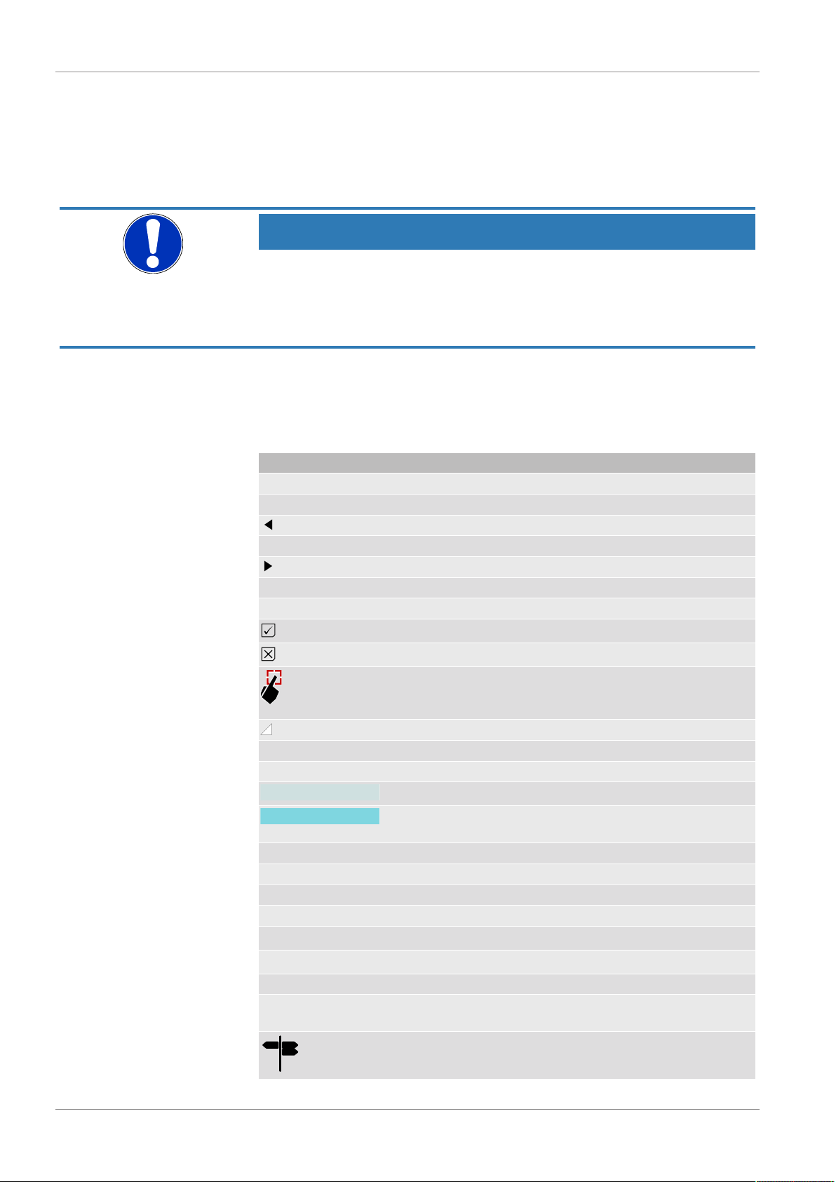
1.8 Pictogram explanation ..............................................................................................................................6
2 Product and functional description ..............................................................................................................7
2.1 Use as intended........................................................................................................................................7
2.2 Function diagram ......................................................................................................................................7
2.3 Design and mode of operation..................................................................................................................8
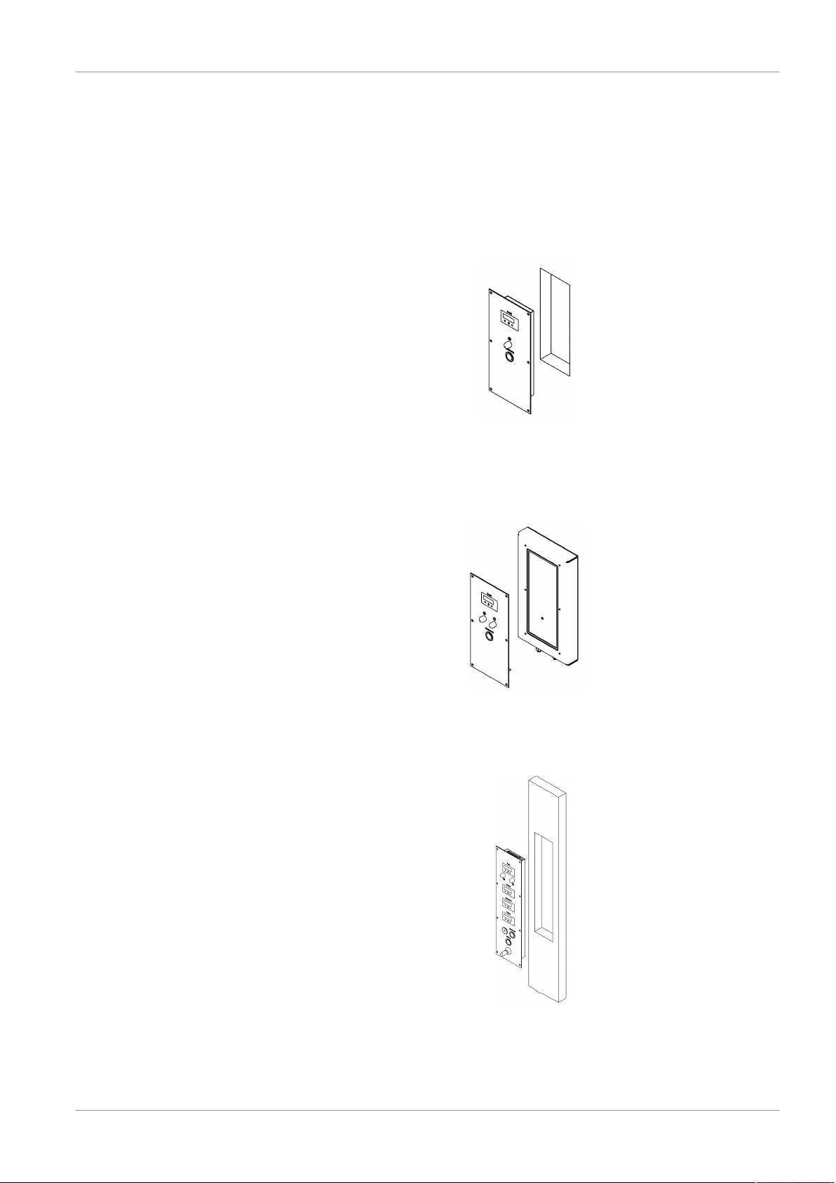
3 Installation and assembly..............................................................................................................................9
4 Commissioning.............................................................................................................................................10
4.1 General ...................................................................................................................................................10
4.2 Measured value display ..........................................................................................................................11
4.2.1 Tile view ...................................................................................................................................... 11
4.2.2 List view ...................................................................................................................................... 13
4.2.3 Presentation variants .................................................................................................................. 15
4.3 Control elements.....................................................................................................................................16
5 Parameterization...........................................................................................................................................18
5.1 General Information ................................................................................................................................18
5.2 Navigation in the menu tree....................................................................................................................18
5.3 Value input..............................................................................................................................................19
5.3.1 Input of number values ............................................................................................................... 19
5.3.2 Text input .................................................................................................................................... 19
5.3.3 Select parameter values ............................................................................................................. 20
5.3.4 Dialogue box ............................................................................................................................... 20
5.4 Main menu [Level 1] ...............................................................................................................................21
5.4.1 Menu: History [Level 2] ............................................................................................................... 22
5.4.1.1 Graphic display ........................................................................................................... 22
5.4.2 Menu: Event log [Level 2] ........................................................................................................... 29
5.4.3 Menu: Log on / log off [Level 2]................................................................................................... 30
5.4.4 Menu: Configuration [Level 2] ..................................................................................................... 31
5.4.4.1 Menu: Display [Level 3] ............................................................................................... 32
5.4.4.2 Menu: Switch outputs [Level 3] ................................................................................... 33
5.4.4.3 Menu: Inputs [Level 3] ................................................................................................. 40
5.4.4.4 Menu: Outputs [Level 3] .............................................................................................. 68
5.4.4.5 Menu: Datalogger [Level 3] ......................................................................................... 72
5.4.5 Menu: Language [Level 2] .......................................................................................................... 76

Table of Contents FISCHER Mess- und Regeltechnik GmbH
4 / 88 BA_EN_EA16
5.4.6 Menu: System [Level 2] .............................................................................................................. 76
5.4.6.1 Menu: Configuration [Level 3] ..................................................................................... 77
5.4.6.2 Menu: Overview inputs/outputs [Level 3] .................................................................... 77
5.4.6.3 Menu: System info [Level 3] ........................................................................................ 78
5.4.6.4 Menu: Firmware update [Level 3]................................................................................ 79
5.4.6.5 Menu: Date/Time [Level 3] .......................................................................................... 79
5.4.6.6 Menu: Unmount SD card [Level 3] .............................................................................. 80
5.4.6.7 Menu: Data transfer SD->USB [Level 3] ..................................................................... 81
5.4.6.8 Menu: Convert log data [Level 3] ................................................................................ 81
5.4.6.9 Menu: Delete SD card [Level 3] .................................................................................. 82
5.4.6.10 Menu: Change passwords [Level 3]............................................................................ 82
6 Technical data...............................................................................................................................................83
6.1 Generalities.............................................................................................................................................83
6.2 Input variables ........................................................................................................................................83
6.2.1 Analogue inputs A1 ... A4 ........................................................................................................... 83
6.2.2 Digital inputs I/O1 ... I/O4............................................................................................................ 83
6.3 Output parameters..................................................................................................................................83
6.3.1 Analogue outputs A1 ... A4 ......................................................................................................... 83
6.3.2 Digital outputs I/O1 ... I/O4.......................................................................................................... 84
6.3.3 Switching outputs K1 ... k4.......................................................................................................... 84
6.4 Measurement accuracy ..........................................................................................................................84
6.5 Digital interfaces .....................................................................................................................................85
6.6 Display and operating interface ..............................................................................................................85
6.7 Auxiliary energy .....................................................................................................................................85
6.8 Application conditions .............................................................................................................................85
6.9 Construction design ................................................................................................................................85
7 Order Codes..................................................................................................................................................86
8 Attachments..................................................................................................................................................87
8.1 EU Declaration of Conformity .................................................................................................................87

FISCHER Mess- und Regeltechnik GmbH Safety guidelines | 1
BA_EN_EA16 5 / 88
1 Safety guidelines
1.1 General
WARNING
This operating manual contains instructions fundamental to the installation, op-
eration and maintenance of the device that must be observed unconditionally. It
must be read by the assembler, operator and the specialized personnel in
charge of the instrument before it is installed and put into operation.
This operating manual is an integral part of the product and therefore needs to
be kept close to the instrument in a place that is accessible at all times to the re-
sponsible personnel.
The following sections, in particular instructions about the assembly, commis-
sioning and maintenance, contain important information, non-observance of
which could pose a threat to humans, animals, the environment and property.
The instrument described in these operating instructions is designed and manu-
factured in line with the state of the art and good engineering practice.
1.2 Personnel Qualification
The instrument may only be installed and commissioned by specialized person-
nel familiar with the installation, commissioning and operation of this product.
Specialized personnel are persons who can assess the work they have been
assigned and recognize potential dangers by virtue of their specialized training,
their skills and experience and their knowledge of the pertinent standards.
1.3 Risks due to Non-Observance of Safety Instructions
Non-observance of these safety instructions, the intended use of the device or
the limit values given in the technical specifications can be hazardous or cause
harm to persons, the environment or the plant itself.
The supplier of the equipment will not be liable for damage claims if this should
happen.
1.4 Safety Instructions for the Operating Company and the Operator
The safety instructions governing correct operation of theinstrument must be
observed. The operating company must make them available to the installation,
maintenance, inspection and operating personnel.
Dangers arising from electrical components, energy discharged by the medium,
escaping medium and incorrect installation of the device must be eliminated.
See the information in the applicable national and international regulations.
Please observe the information about certification and approvals in the Tech-
nical Data section.
1.5 Unauthorised Modification
Modifications of or other technical alterations to the instrument by the customer
are not permitted. This also applies to replacement parts. Only the manufacturer
is authorised to make any modifications or changes.

1 | Safety guidelines FISCHER Mess- und Regeltechnik GmbH
6 / 88 BA_EN_EA16
1.6 Inadmissible Modes of Operation
The operational safety of this instrument can only be guaranteed if it is used as
intended. The instrument model must be suitable for the medium used in the
system. The limit values given in the technical data may not be exceeded.
The manufacturer is not liable for damage resulting from improper or incorrect
use.
1.7 Safe working practices for maintenance and installation work
The safety instructions given in this operating manual, any nationally applicable
regulations on accident prevention and any of the operating company's internal
work, operating and safety guidelines must be observed.
The operating company is responsible for ensuring that all required mainten-
ance, inspection and installation work is carried out by qualified specialized per-
sonnel.
1.8 Pictogram explanation
DANGER
Type and source of danger
This indicates a direct dangerous situation that could lead to death or serious
injury (highest danger level).
a) Avoid danger by observing the valid safety regulations.
WARNING
Type and source of danger
This indicates a potentially dangerous situation that could lead to death or ser-
ious injury (medium danger level).
a) Avoid danger by observing the valid safety regulations.
CAUTION
Type and source of danger
This indicates a potentially dangerous situation that could lead to slight or seri-
ous injury, damage or environmental pollution (low danger level).
a) Avoid danger by observing the valid safety regulations.
NOTICE
Note / advice
This indicates useful information of advice for efficient and smooth operation.

FISCHER Mess- und Regeltechnik GmbH Product and functional description | 2
BA_EN_EA16 7 / 88
2 Product and functional description
2.1 Use as intended
The EA16 is a measuring value display unit for measuring transducers with out-
put signals for current and voltage acc. to IEC 60381. Up to four measuring
transducers in two or three-conductor versions can be connected.
Typical applications
• Measured value display in clean room
Important features
• 3.5" (8.9 cm) TFT Touch LCD colour display
• Configurable colour switching
• 2 or 4 channel mode with …
– 2 or 4 configurable analogue inputs
for uniform signals (0/4 … 20 mA, 0 … 10 V) acc. to IEC 60381
(signal ranges ca be selected freely within the limits; see Technical
Data)
– 2 or 4 configurable analogue outputs
with possibility of characteristic curve spread and reversal with any off-
set
– 2 or 4 configurable switching outputs
with potential-free relay contacts or semiconductor switches
• USB interface
• Optional Modbus RTU interface
• Optional data logger function with data storage on Micro SD card
• Configuration of all parameters and a measuring point protocol(1) are pos-
sible via PC software
2.2 Function diagram
1E
2E
3E
4E
USB
SD
A
D A
DA1
A2
A3
A4
K1
K2
K3
K4
CPU
21
3
4
5
6
Modbus RTU
7
Fig.1: Function diagram
1 Analogue inputs 2 Analogue outputs
3 Touch colour display 4 Switching outputs
5 Micro SD memory card 6 Micro USB interface
7 Modbus interface (option)
(1) parameter profile

2 | Product and functional description FISCHER Mess- und Regeltechnik GmbH
8 / 88 BA_EN_EA16
2.3 Design and mode of operation
The measuring signals of up to four connected measuring transducers can be
analysed simultaneously by the microcontroller electronics. The configurable
3.5" touch display can display up to four measuring values at the same time. A
configurable colour switch serves to present specific operating modes. Option-
ally, the device can be delivered with a data logger function.
The processed input signals are converted into the following output signals:
• 2 or 4 configurable switching outputs. Parameters, such as activation and
deactivation points, switching function or delay, are available for this pur-
pose. The switching states are displayed with symbols on the display.
• 2 or 4 analogue outputs with configurable output range. Every output signal
can be set freely within the signal limits (see Technical Data). The charac-
teristic curve change can be made in a linear, rooted, tabular or mathematic
form proportional to the displayed value.
The unit also has a Modbus interface and can be connected to a Modbus RTU
network as a slave. For more information about this topic, please reference the
product user manual and the Modbus reference manual.
(http://www.fischermesstechnik.de/en/downloads/manuals)
All parameters can also be set on the device via the touch display or (optionally)
via a PC software. The measuring value display unit has a USB interface to
which a USB stick can be connected. For instance, the USB stick can be used
to allow simple configurations to be exported to other devices. The PC software
also allows a measuring point protocol (2) .
(2) parameter profile

FISCHER Mess- und Regeltechnik GmbH Installation and assembly | 3
BA_EN_EA16 9 / 88
3 Installation and assembly
The EA16 is designed for panel installation and is supplied fully assembled.
Please see the supplied electro-technology documents for the dimensional
drawings and information about the electrical connection of the panel. Panels
can always be supplied in the following mounting types.
Wall-mounting
Via a recess in the wall in the clean room. The minimum installation depth is 49
mm. The panel is attached with sunk-head screws.
Fig.2: Wall-mounting
Surface installation
Via surface-mounted housing on the wall of the clean room. The minimum in-
stallation depth is 52 mm. The panel is attached to the surface-mounted hous-
ing with sunk-head screws.
Fig.3: Surface installation
Channel assembly
Via a cut-out in the channel The minimum installation depth is 49 mm. The
panel is attached with sunk-head screws.
Fig.4: Channel installation

4 | Commissioning FISCHER Mess- und Regeltechnik GmbH
10 / 88 BA_EN_EA16
4 Commissioning
4.1 General
All electrical supply, operating and measuring lines, and the pressure connec-
tions must have been correctly installed before commissioning.
NOTICE
Illustrations
All illustrations are examples to demonstrate a certain situation. The contents of
the screen may vary greatly on the unit. For instance, the names of the input
channels can be freely selected; the status displays for the switch outputs can
be hidden and lots more.
Pictogram explanation
This table explains how the different objects (menu, parameters, etc.) are
shown in the text of these operating instructions. Due to modifications to the
background colour, the colour of the presentation of some symbols on the
screen may vary.
Symbol Description
Operating keys
þ
Increasing
W
Left
û
OK
X
right side
ÿ
decreasing
Esc
Cancel
yes on
N/a Off
Touch the screen (with your hand or stylus
pen), the symbol may be in a different col-
our
Paging symbol
Menu
Parameters
Menu name (button)
Parameters
Menu and/or parameter not valid under cer-
tain conditions.
File Parameter name
<Value> System parameter value
Access Rights
T
No access
V
read only
NOTICE!Swipe function Important comments
e.g. only swipe function
Further left

FISCHER Mess- und Regeltechnik GmbH Commissioning | 4
BA_EN_EA16 11 / 88
4.2 Measured value display
There are two options for the measured value display presentation.
• Tile view
• List view
The colour of the individual chapters can be changed depending on the respect-
ive input signal. To do this, certain thresholds are configured for each colour in
the menu
Colour change
. The associated colours represent the respective
operating statuses.
In the list view, the background shadowing and the warning symbol assume the
function of the tiles. The colours are controlled depending on the input signal
like the tiles.
Depending on the unit model (2-channel/4-channel), there are different present-
ation variants [}15] for the measured value display.
4.2.1 Tile view
Pressure Pa
35.8
E1O2
O4
O3
Humidity %rF
55
Temp °C
24.7
Particle ppm
12803
PQ
2
3
1
4
5 6
Monitoring sluice 1
7
Channel 1 Channel 2
Channel 4Channel 3
O-
Status bar T
8
Fig.5: Measured value display
1 Channel name 2 Einheit
3 Measurement 4 Status switch output
5 Status SD card 6 Status USB
7 Unit designation
or Date / Time
8 Login symbol
S1
R1
Contact switched
Contact not switched
R-No contact assigned
Fig.6: Status display
The example of a switch output demonstrates how the status display works.
1. The symbol for the switch output lights up, if the contact is switched.
2. The backlighting disappears, if the contact is not switched. The contact
symbol is shown in grey.
NOTICE!Back lighting
The backlighting colour is usually white. However the backlighting for a yellow
tile is black.
In the status displays for the SD card and USB interface, access to the medium
is symbolised by orange backlighting. The green backlighting shows that a unit
is connected. The backlighting is grey, if no unit is connected.
A logged-in user is shown by the login symbol. If the user is inactive, he will be
automatically logged out after a timeout time has expired.

4 | Commissioning FISCHER Mess- und Regeltechnik GmbH
12 / 88 BA_EN_EA16
Detail view channel 1
Fig.7: To detail view
Tip the respective tile to go to the detail view of a channel. Return to the meas-
ured value screen in the same way. The following uses the detailed view of the
first channel to demonstrate all channels.
Pressure Pa
35.8
E1O2
PQMonitoring sluice 1
50.00
0.00
-50.00
Warning:
Alarm: 30.00 Pa
25.00 PaWarning:
Alarm:
15.00 Pa
10.00 Pa
1
2
3
2.1
2.2
2.3
2.4
3.1
3.4
3.2
3.3
Fig.8: Detailed view
1 Measurement data display
2 Status display 3 Trend display
2.1 Alarm: Threshold value high - red 3.1 Current measured value
2.2 Warning: Threshold value high - yellow 3.2 Measuring range
2.3 Warning: Threshold value low - yellow 3.3 Colour change
2.4 Alarm: Threshold value low - red 3.4 Limit lines of the
thresholds
Status display
The page symbol shows that there are more screen pages in the status dis-
play. Touch anywhere on the status display to show the next page.
Pressure Pa
35.8
E1O2
PQMonitoring lock 1
50.00
0.00
-50.00
Warning:
Alarm: 30.00 Pa
25.00 PaWarning:
Alarm:
15.00 Pa
10.00 Pa
1
2
Fig.9: Status display
1 Status display 2 Paging symbol

FISCHER Mess- und Regeltechnik GmbH Commissioning | 4
BA_EN_EA16 13 / 88
The second page of the status display appears. Touch anywhere on the status
display to show the next page. At the end, you automatically return to the first
page.
Pressure Pa
35.8
E1O2
PQMonitoring sluice 1
50.00
0.00
-50.00
Pressure too high
1
2
Fig.10: Detail view alarm message
1 Message high - red (input 1) 2 Paging symbol
4.2.2 List view
Pressure
S135.8Pa
2
Humidity
S355%rF
Temp.
S424.7°C
Particle 12803ppm
PQMonitoring sluice 1
S-
Channel 1
Channel 2
Channel 3
Channel 4
1 23
4
5 6 7
89
Status bar T
10
C
B
C
B
C
B
C
B
C
Fig.11: Measured value display
1 Channel name 2 Einheit
3 Measurement 4 Status switch output
5 Status SD card 6 Status USB
7 Unit designation
or Date / Time
8 Warning signs
9 Background shadowing 10 Login symbol
S1Contact switched
Contact not switched
R1
No contact assigned
R-
Fig.12: Status display
The example of a switch output demonstrates how the status display works.
1. The symbol for the switch output goes orange, if the contact is switched.
2. The symbol for the switch output goes grey, if the contact is idle.
NOTICE!Back lighting
In the status displays for the SD card and USB interface, access to the medium
is symbolised by orange backlighting. The green backlighting shows that a unit
is connected. The backlighting is grey, if no unit is connected.
A logged-in user is shown by the login symbol. If the user is inactive, he will be
automatically logged out after a timeout time has expired.

4 | Commissioning FISCHER Mess- und Regeltechnik GmbH
14 / 88 BA_EN_EA16
Detail view channel 1
Fig.13: To detail view
Tip the respective list entry to go to the detail view of a channel. Return to the
measured value screen in the same way. The following uses the detailed view
of the first channel to demonstrate all channels.
Pressure
S135.8 Pa
2
PQMonitoring sluice 1
50.00
0.00
-50.00
Pressure too high
Warning:
Alarm: Alarm:
Warning:15.00 Pa
10.00 Pa
25.00 Pa
30.00 Pa
1
2
2.1
2.3 2.2
2.12.4
3
3.4 3.1
3.2
3.3
C
B
C
Fig.14: Detailed view
1 Measurement data display
2 Status display 3 Trend display
2.1 Alarm: Threshold value high - red 3.1 Current measured value
2.2 Warning: Threshold value high - yellow 3.2 Measuring range
2.3 Warning: Threshold value low - yellow 3.3 Colour change
2.4 Warning: Threshold value low - red 3.4 Limit lines of the
thresholds

FISCHER Mess- und Regeltechnik GmbH Commissioning | 4
BA_EN_EA16 15 / 88
4.2.3 Presentation variants
The unit is available in a 2-channel and 4-channel version. This setting is made
ex-works.
The detail views are identical to the detail views of the 4-channel version.
The analogue inputs on both versions can be switched off individually. This
status is indicated by OFF in the respective tile (or list). If two analogue outputs
are switched in the 4-channel version, the presentation variant of the 2-channel
model is shown on the measured value display.
2-channel tile view
PQMonitoring sluice 1
Channel 1
Channel 2
Status bar T
Temperature error °C
24.7
O1
Humidity %rF
55
O2
Fig.15: 2-channel measured value display
2-channel list view
Humidity
S255%rF
Temp.
S124.7°C
PQMonitoring sluice 1
Channel 1
Channel 2
Status bar T
Warning
Alert
°C20.0
15.0 °C
Warning
Alert
°C20.0
15.0 °C
Warning
Alert
%rF35,000
20,000 %rF
Warning
Alert
%rF55,000
70,000 %rF
B
C
C
B
C
Fig.16: 2-channel measured value display

4 | Commissioning FISCHER Mess- und Regeltechnik GmbH
16 / 88 BA_EN_EA16
4.3 Control elements
The unit is equipped with a TFT Touch LCD colour display. It is operated via a
list menu and the input interfaces that depend on the functions.
The touch function is not explained because so many devices have this state-
of-the-art function.
We recommend using a stylus pen.
Fig.17: Menu input
Example: Password input
Touch anywhere on the status bar to go to the menu. The following menu ap-
pears on the screen:
P
Esc
K
J
I
Log-in
Event log
History
Parameterization
Sprache (language)
T
T
T
QMain menu/
Menu bar
Escape button
OK button
Arrow button
upwards
Arrow button
downwards
Operating keys
Status bar
Menu path
Menu item
selected
Access rights
T
Fig.18: Main menu
The dotted red line marks the picture section. This can be moved using the ar-
row keys
þ
ÿ
, the arrow shows the respective direction.
The menu entry in the centre of the screen is always selected and opened by
pressing the OK button
û
. Alternatively, a menu entry can also be touched to
open it.
In this example, the screen opens when a password is entered. The menu path
shows where you are in the menu tree.
P
Esc
W
J
X
QMain menu/login/
DEL
1230
4 5 6 -
789
Please enter your password
Menu path
Fig.19: Main menu/login

FISCHER Mess- und Regeltechnik GmbH Commissioning | 4
BA_EN_EA16 17 / 88
Enter the password and complete the input by pressing the OK button
û
. A
message appears on the screen stating which user you have logged in with.
Once you have acknowledged the message, you return to the main menu.
The following user profiles are used:
User Rights
View The user only has read rights for the configuration options.
Expert The user may change some of the configuration options. The
user has no access to the passwords.
Admin The user may change all the configuration options. However the
user only has access to the passwords of the subordinate user
levels.
Supervisor This user has full access to all parameters and passwords.

5 | Parameterization FISCHER Mess- und Regeltechnik GmbH
18 / 88 BA_EN_EA16
5 Parameterization
5.1 General Information
The EA16 is a highly complex measured value display with a control system
that can be learned intuitively. Due to its complex structure and the possibility of
supplementing functions by means of a firmware update, it is not possible to
present all functions in details in these operating instructions.
The following describes the basic functions of the unit and how they are used.
NOTICE
Value ranges
The presented value ranges of the parameters correspond to the default values
of the factory configuration. If certain parameters are changed (e.g. measuring
range), the value ranges of the dependent parameters (e.g. thresholds) are
automatically adjusted. For this reason, the actually displayed value ranges may
differ from the value ranges shown in these instructions. The latter only serves
as a typical example.
5.2 Navigation in the menu tree
The menu can have up to six levels. There are several user profiles with various
read/write rights are filed in the user administration. Access to the menus and
parameter settings depends on the user.
The menu tree is navigated based on the following scheme:
P
Esc
K
J
I
Log-in
Event log
History
Configuration
Language
T
QMain menu/
V
V
P
Esc
K
J
I
Inputs
Switch outputs
Display
Outputs
Data logger
T
QMain menu/Configuration/
V
V
P
Esc
K
J
I
Configuration
Log off
Event log
Language
System
QMain menu/
V
V
Level 1 Level 2 Level 1
(a) Level change by direct tapping
(b) Level change by positioning the screen section
P
Esc
K
J
I
Log-in
Event log
History
Configuration
Language
T
QMain menu/
V
V
P
Esc
K
J
I
Configuration
Log off
Event log
Language
System
QMain menu/
V
V
P
Esc
K
J
I
Inputs
Switch outputs
Display
Outputs
Data logger
T
QMain menu/Configuration/
V
V
Level 2Level 1 Level 1 Level 1
P
Esc
K
J
I
Configuration
Log off
Event log
Language
System
QMain menu/
V
V
Fig.20: Navigation menu tree

FISCHER Mess- und Regeltechnik GmbH Parameterization | 5
BA_EN_EA16 19 / 88
5.3 Value input
The following provides a description of the input interfaces that are used to
enter the values. A differentiation is made between the input of numbers and
the input of texts. The screens shown are examples only and may vary in terms
of their layout and presentation.
Their functionality can be learned intuitively and is always based on the same
principle.
5.3.1 Input of number values
P
ESC
W
J
X
QInput signal.../Signal min./
DEL
1230
4 5 6 .
789
min.: 0.000V max.: 10.5000V
Menu path
allowed value range
Input field
10-digit keypad
Cursor
Navigation
-
changes to a
minus sign
0
Fig.21: Number input
Negative integers can be entered by deleting the number value (0 in the ex-
ample) in the display. The decimal point then changes to a minus sign and can
be used.
5.3.2 Text input
P Q Analogue input.../Designation/
... Pressure
A
N
B C D E F G H I J
K L M N O P Q R S T
U V W X Y S J
Menu path
Input fieldCursor
Keyboard Layout
Back button
Space button OK button
Fig.22: Text input
The key … is used to change the assignment of the key pad, and lower case
letters, numbers and special characters can be used.

5 | Parameterization FISCHER Mess- und Regeltechnik GmbH
20 / 88 BA_EN_EA16
5.3.3 Select parameter values
Some inputs are made by selecting defined parameter values. This occurs
either by switching the button or by selection from a list.
Changeover button
ESC
K
J
I
Contact type: Make contact
Function: Window
Window max.
Switch out.../Switch output 1/
P Q
Assignment: Input 1
Button
Make contact
Break contact
g f
Fig.23: Select parameter values
Touch the button to change the parameter value. The set value is saved with
the button
û
.
Selection list
Touch the button to open the parameter. A screen as shown appears.
ESC
K
J
I
Assignment: Input 1
Contact type: Make contact
Function: Window
Switch out.../Switch output 1/
P Q
f
g
Value list
Input 3
Input 4
Input 1
Input 2
Colour change
Input -
f
g
f
f
g
g
f
Fig.24: Select parameter values
You can navigate the value list using the buttons
þ
and
ÿ
. The set value is
saved with the button
û
.
5.3.4 Dialogue box
YES
Accept
changes?
NO
Fig.25: Dialogue box
This or a similar dialogue box appears, if the user needs to confirm something.
Parameter changes are accepted after they have been confirmed with Yes, and
are logged in the activated event log. If rejected with NO, the changes are can-
celled.
Table of contents
Other FISCHER Monitor manuals