Important!
Disconnect power to surrounding appliances before preparing cavity.
Recommended to allow the vertical removal of the refrigerator bins.
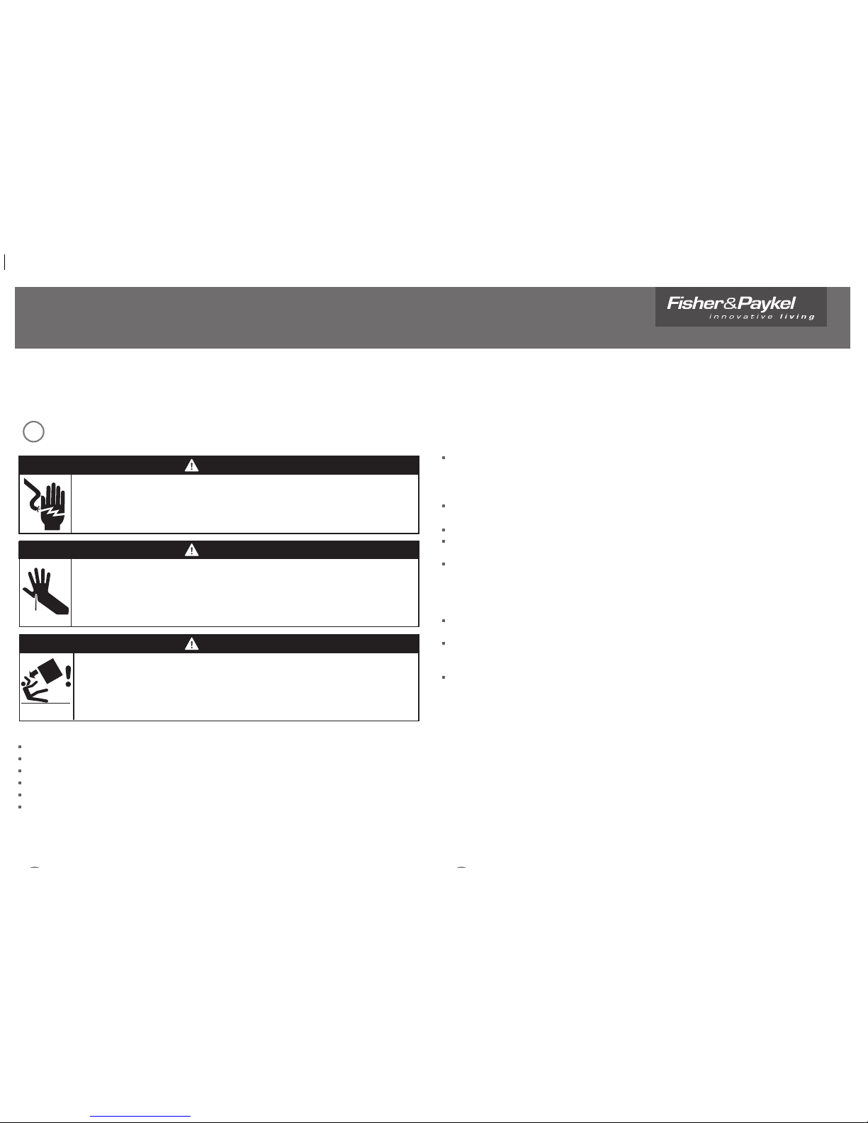
WARNING!
Electrical shock hazard
Disconnect product from main power supply before installing appliance.
Failure to do so may result in electrical shock or death
Important safety precautions!
Installation of the CoolDrawer requires competent mechanical and electrical skills.
Be sure to leave these Instructions with the Customer.
Installation must comply with your local building and electricity regulations.
At the completion of the CoolDrawer installation, the Installer must perform the Final Check List.
Remove all packaging materials supplied with the CoolDrawer.
The CoolDrawer is manufactured for indoor use only.
Important!
SAVE THESE INSTRUCTIONS
The models shown in this document may not be available in all markets and are subject to change at any time. For current details about model and specification availability in your country, please go to our
website www.fisherpaykel.com or contact your local Fisher & Paykel dealer.
SAFETY AND WARNINGS
WARNING!
Cut hazard
Take care - panel edges are sharp.
Failure to use caution could result in injury or cuts.
1
2
The CoolDrawer MUST be installed to allow for future removal from the enclosure if service is required.
Do not seal the CoolDrawer into the cabinetry with silicone or glue. Doing so will make future servicing
difficult. Fisher & Paykel will not be liable for any costs associated with removing or replacing a sealed-in
product, nor for repairing any damage that may be incurred by doing this.
Care should be taken when the appliance is installed or removed to reduce the likelihood of damage to the
power supply cord.
Failure to install the CoolDrawer correctly will invalidate any warranty or liability claims.
If the power supply cord is damaged, it must be replaced. Parts are available from your Authorised
Fisher & Paykel dealer.
Cabinetry must be sufficiently robust to support a combined product and food load of 220 lb (100 kg).
Bearers may be required to support the internal shelf.
Before you install the CoolDrawer, please make sure that
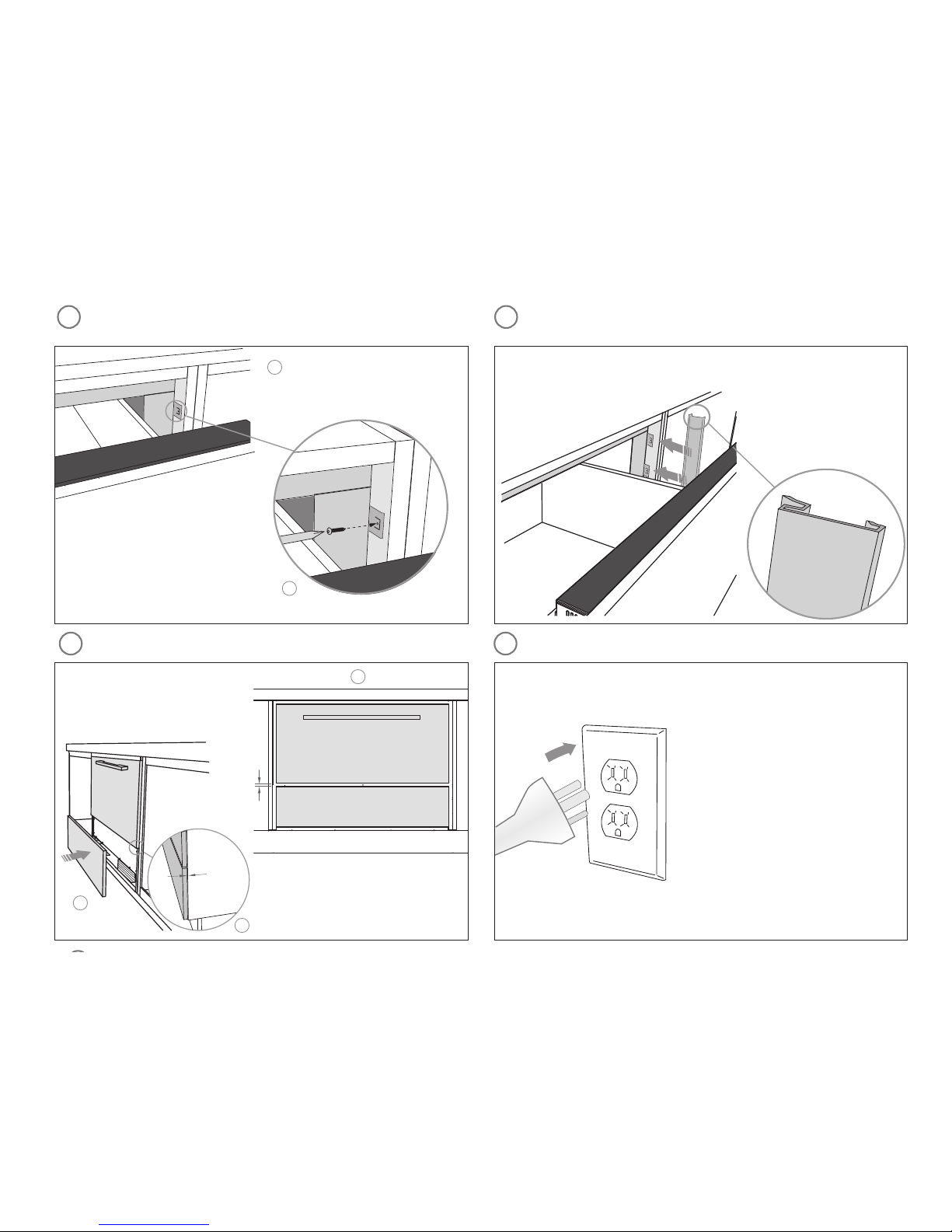
The switched power outlet must be outside the refrigerator drawer cavity so that it is accessible after
installation.
The switched power outlet must be located outside the cavity, within 55” (1400 mm) from the CoolDrawer
cavity if situated on the left-hand side of the cavity and within 33” (840 mm) if situated on the right-hand
side of the cavity.
The services hole in the refrigerator cavity needs to be large enough for the power supply plug to fit
through.
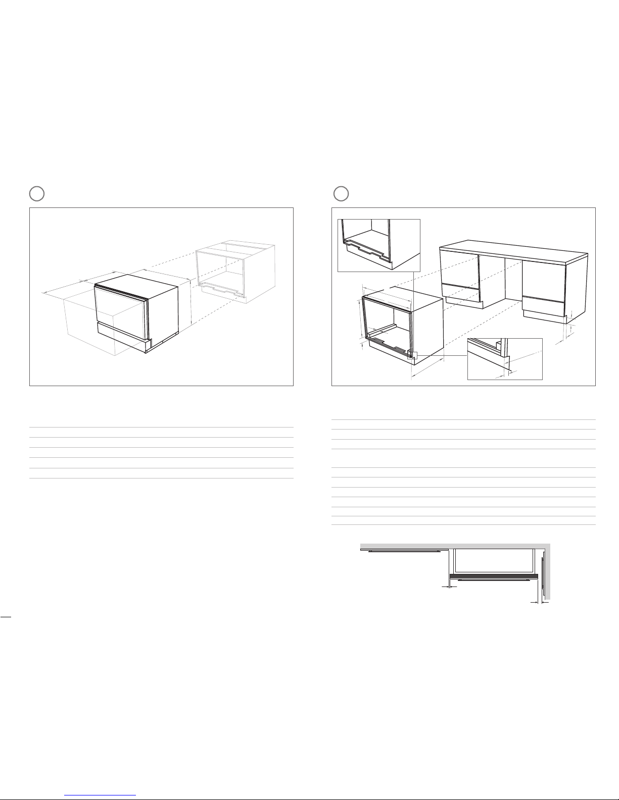
PRODUCT DIMENSIONS
PARTS SUPPLIED
4
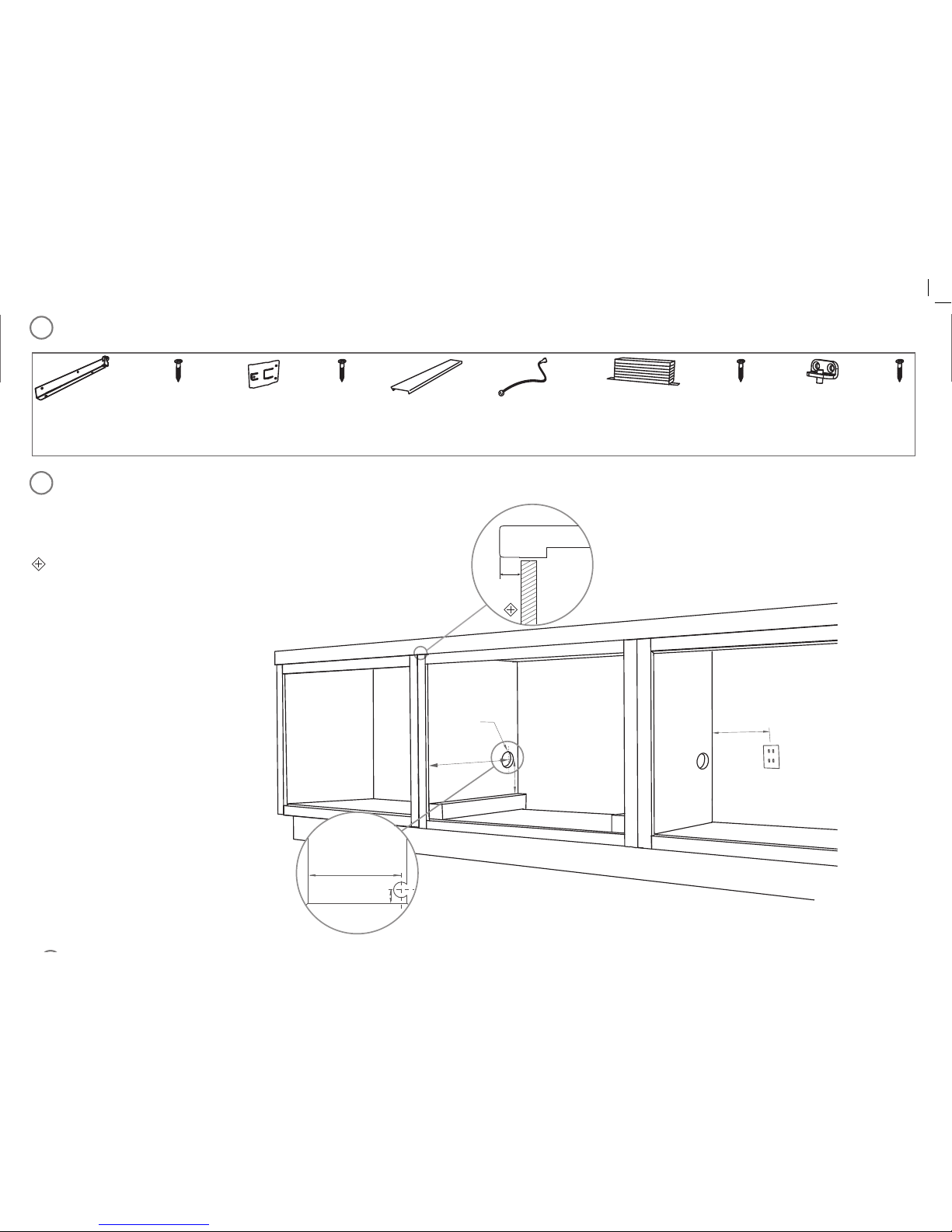
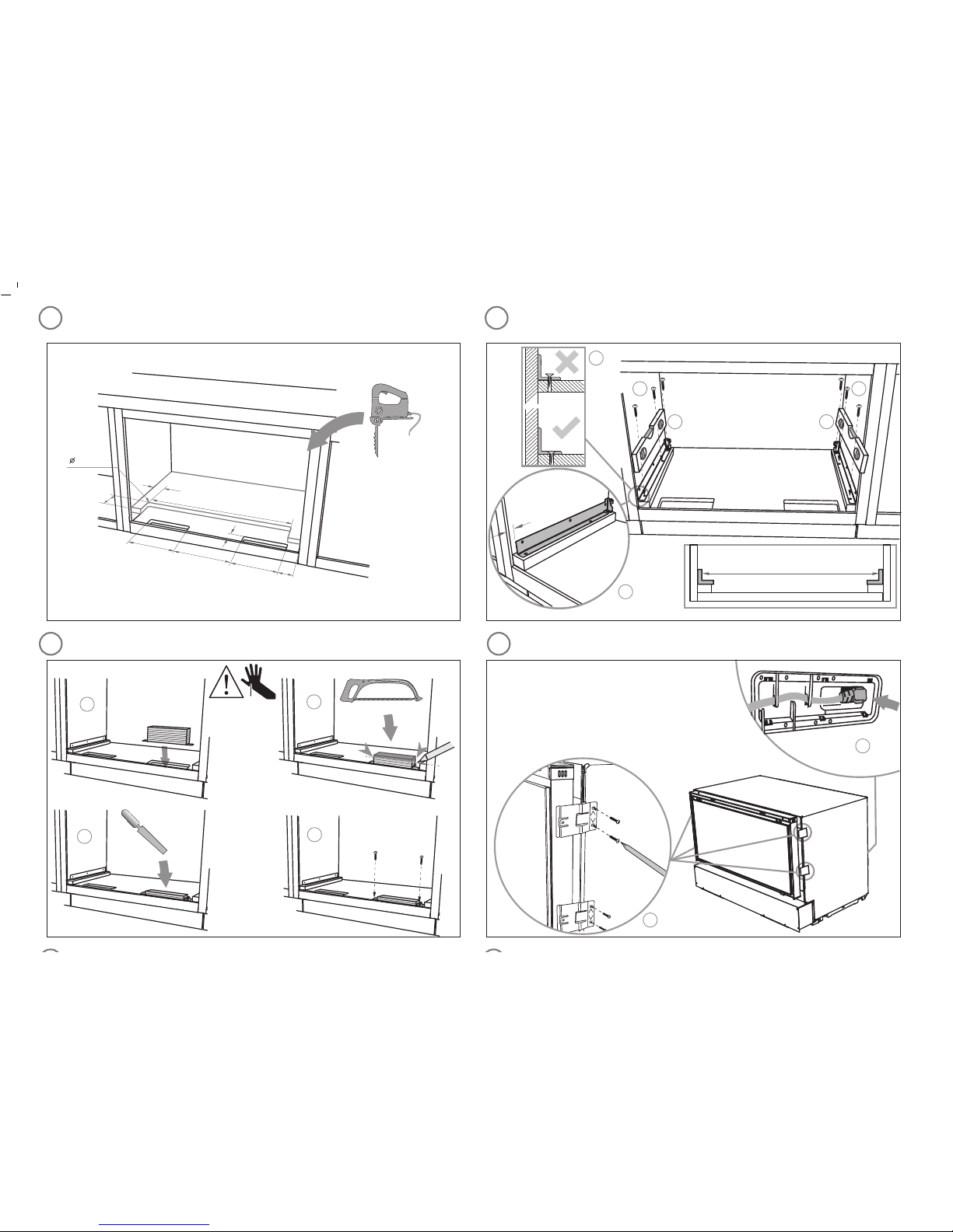
5CAVITY PREPARATION
IZONA CoolDrawer
Installation instructions
FRAMED CABINETRY
WARNING!
Tipping hazard
Do not operate this apppliance until it has been securely anchored inside the
cabinetry. The cabinet must be securely anchored to the floor.
Failure to use caution could result in injury or cuts.
Product dimensions (inches [mm])
CoolDrawer
RB36S
RB90S
Aoverall height of product (inc. installation brackets) 25 /” (640)
Boverall width of product 33 /” (855)
Coverall depth of product (excl. drawer panel; inc. power cord) 21 /” (557)
Ddepth of drawer (open) (excl. handle) 20 ½” (520)
Installation diagrams for illustration purposes only
A
Cabinetry dimensions (inches [mm])
CoolDrawer
RB36S
RB90S
Aoverall width of cabinetry frame 36” (914)
Bminimum inside width of cabinetry frame 34” (864)
Cheight from frame inner face to top of spacer block 25 /” (644)
Dheight below top of spacer block to frame inner*
(to allow for outlet duct height)
max. 4 /” (120)
min. /” (21)
Eminimum height of toe kick 3” (75)
Fminimum depth** of toe kick 1 /” (40)
Gminimum distance from front of cabinetry to rear wall 22 /” (560)
Hwidth of spacer blocks 1 /” (50)
*Minimum internal height of cabinetry frame can be 25 /” (644mm) if outlet duct is not used.
**All depth measurements are taken from the front face of the cabinetry frame (not drawer panel)
Minimum clearances (inches [mm])
/” (2 mm)
½” (13 mm)
E
Installation diagrams for illustration purposes only
B
C
D
G
F
F
C
D
H
G
A
B
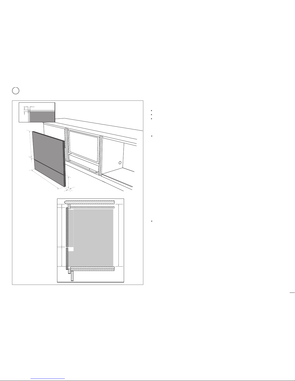
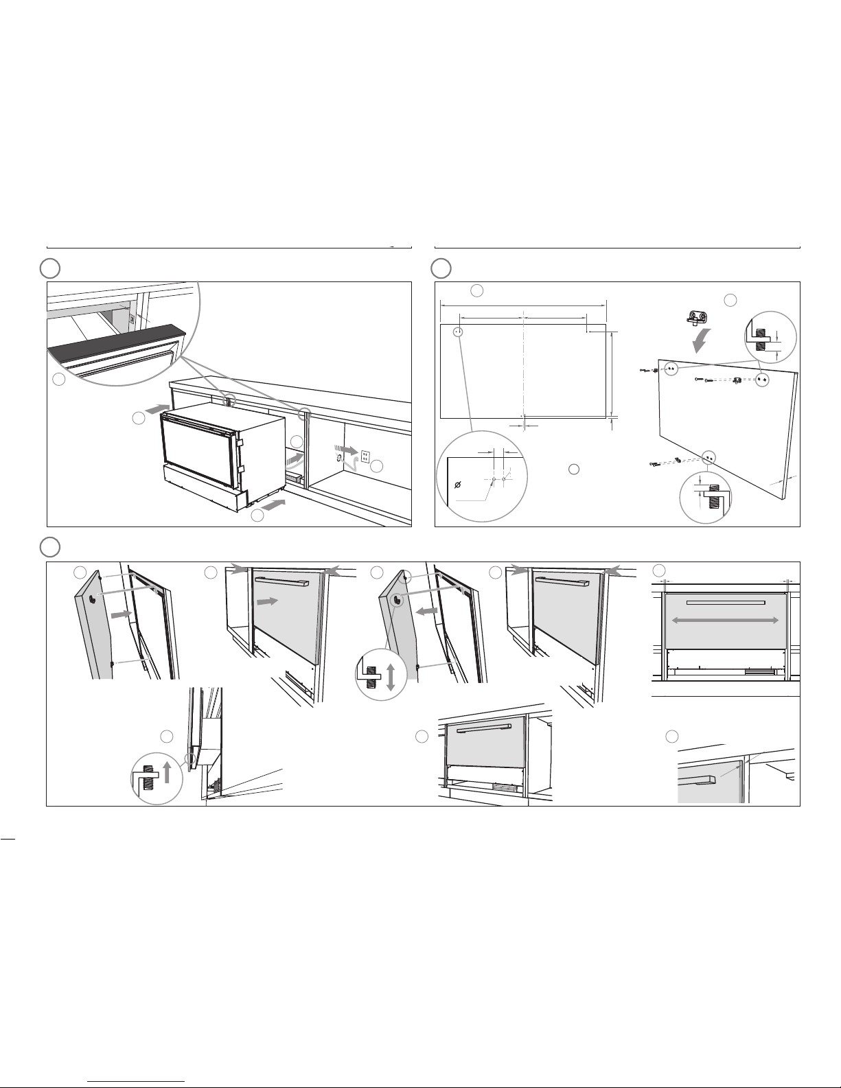
6PANEL PREPARATION
Integrated Panel material
/
-
/”
(16 - 20 mm) panel thickness (
¾”
[18 mm] recommended).
Maximum weight of 15.5 lb (7 kg).
Adequately sealed to withstand moisture (122
O
F/50
O
C @ 80% RH)
max.
¾” (20 mm)
max.
33”
(840
mm)
min. ø
1 /” (
50 mm)
Benchtop
Panel
min. 21”
(
535 mm)
Height of Drawer Panel
The following information is required to correctly define your drawer panel height:
Dimension Data Source
AReveal dimension Your kitchen designer
BHeight between top of spacer block and Your kitchen designer
underside of benchtop
CBottom face of Drawer panel to top of spacer block Your kitchen designer
(Min. 6” [152 mm])
(Max. 7
¼
” [184 mm])
DDrawer panel height Calculated from A, B & C
To calculate D complete the following equation:
D = B - A - C
i.e. For the F&P prefinished panel with a
¼
“ (6 mm) reveal:
18
¾
” (476 mm) = 26
¼
” (666 mm) -
¼
” (6 mm)
-
7
¼
” (184 mm)
Height of the False Panel
Determine the height of the false panel according to your individual kitchen cabinetry
requirements maintaining a
/
” (4 mm) gap between panels.
F&P prefinish panel width is 35
¼
” (896 mm)
F&P prefinish panel height (D) is 18
¾
” (476 mm)
Installation diagrams for illustration purposes only
Drawer Panel
/
-
/”
(16 - 20mm)
height of False
Panel
A
A
False Panel
width of Panels
D
height of
Drawer Panel
min.
5” (
130 mm)
/”
(4 mm)
An internal shelf can be used as an alternative to spacer blocks to
position the product at the correct height. In this case additional
cutouts will be required. Refer to Step 7.
Installation
trims (2)
Installation brackets
(left-hand and right-
hand side) (2)
Outlet duct (1)Trim brackets (4) Drawer Panel
attachment
hooks (3)
Power
cord (1)
Phillips 16 mm
(
/” )
wood
screw (6)
Pan Head
16 mm (
/” )
screw (12)
Pan Head
16 mm (
/” )
screw (2)
Phillips
16 mm
(
/” )
wood
screws (6)
3CABINETRY DIMENSIONS
Note: Services can be located
either side of CoolDrawer.
min.
21” (
535 mm)
min.
5” (
130 mm)
SIDE VIEW
Benchtop
Drawer panelFalse panel
A
D
C
B
Shows cutout if cabinetry
depth at
21 /” (
550 mm)
RB36S & RB90S models