Fisher Engineering EZ-V User manual

SNOWPLOW
MECHANIC'S GUIDE
Fisher Engineering
July 1997
No. 21856
CAUTION: Read this manual before servicing the FISH R® Z-V snowplow.

No. 21856 July 1997
2
PR FAC
This guide has been prepared to
assist the trained mechanic in the
service of FISHER® snowplows. It
also provides safety information and
recommendations. We urge all
mechanics to read this manual
carefully before attempting to service
the FISHER snowplow e uipment
covered by this guide.
Service of your FISHER snowplow
e uipment is best performed by your
local Fisher outlet. They know your
snowplow best and are interested in
your complete satisfaction.
TABL OF CONT NTS
Preface .............................................................................................................2
Safety Information ...........................................................................................3
Tools Re uired ................................................................................................5
Product Specifications ....................................................................................5
Hose Routing ...................................................................................................6
Hydraulic Unit Parts Diagram .........................................................................7
Solenoid Cartridge Valve Identification and Location ..................................8
Relief Valve Identification and Location ........................................................9
Pilot Operated Check Valve Identification and Location ............................10
Vehicle Harness and Vehicle Cable Location .............................................. 11
Operating the Snowplow ..............................................................................12
Theory of Operation ......................................................................................15
Hydraulic and Electrical Schematics ...........................................................17
Electrical Schematic .........................................................................18
Hydraulic Schematic ........................................................................19
Angle Right .......................................................................................20
Angle Left ..........................................................................................22
Right Retract .....................................................................................24
Right Extend .....................................................................................26
Left Retract........................................................................................28
Left Extend ........................................................................................30
Scoop ................................................................................................32
Vee .....................................................................................................34
Raise ..................................................................................................36
Lower .................................................................................................38
Hold in Raise Position Hydraulic ..................................................40
Striking an Object While Plowing Forward Hydraulic.................41
Striking An Object While Back Dragging Hydraulic ....................42
Headlamps Vehicle Only ...............................................................43
High Beam Headlamps With Plow Connected to Vehicle ..............44
Low Beam Headlamps With Plow Connected to Vehicle ...............45
Troubleshooting Guide .................................................................................46
Removable Spring Tool.................................................................................70

No. 21856 July 1997
3
SAF TY INFORMATION
WARNING
Indicates a potentially
hazardous situation that, if not
avoided, could result in death
or serious personal injury .
CAUTION
Indicates a situation that, if not
avoided, could result in minor
personal injury and/or damage
to product or property.
NOTE: Identifies tips, helpful
hints and maintenance
information the owner/operator
should know.
WARNING
Do not exceed GVWR or GAWR
(including blade and ballast) as
found on the driver-side door
cornerpost of the vehicle.
WARNING
Vehicle exhaust contains deadly
carbon monoxide (CO) gas.
Breathing this gas, even in low
concentrations, could cause
death. Never operate a vehicle
in an enclosed area without
venting exhaust to the outside.
WARNING
Hydraulic oil under pressure
could cause skin injection
injury. If you are injured by
hydraulic oil, get medical
treatment immediately.
WARNING
Gasoline is highly flammable
and gasoline vapor is explosive.
Never smoke while working on
vehicle. Keep all open flames
away from gasoline tank and
lines. Wipe up any spilled
gasoline immediately.
WARNING
Remove blade assembly before
placing vehicle on hoist. Failure
to do this could result in
personal injury.
WARNING
Lower blade when vehicle is
parked. Temperature changes
could change hydraulic
pressure, causing the blade to
drop unexpectedly or damaging
hydraulic components. Failure
to do this can result in serious
personal injury.
BEFORE YOU BEGIN
VENTILATION
If you work on the vehicle or
snowplow in a garage or other
enclosed area, be sure to vent
exhaust gas directly to the outside
through a leakproof exhaust hose.
FIRE AND EXPLOSION
Be careful when using gasoline. Do
not use gasoline to clean parts. Store
only in approved containers away
from sources of heat or flame.
Park the vehicle on a level
surface, place shift lever in
PARK or NEUTRAL and set
parking brake.
Leave the snowplow mounted
on the vehicle and lowered for
most service procedures,
unless told otherwise.
PERSONAL SAFETY
Wear only snug-fitting clothing
while working on your vehicle
or snowplow.
Do not wear jewelry or a
necktie, and secure long hair.
Be especially careful near
moving parts such as fan
blades, pulleys and belts.
Wear safety goggles to protect
your eyes from battery acid,
gasoline, dirt and dust.
Avoid touching hot surfaces
such as the engine, radiator,
hoses and exhaust pipes.
Always have a fire extinguisher
rated BC, for flammable li uids
and electrical fires, handy.
HYDRAULIC SAFETY
Always inspect hydraulic
components and hoses before
using. Replace any damaged
or worn parts immediately.
If you suspect a hose leak, DO
NOT use your hand to locate it.
Use a piece of cardboard or
wood.
No. 21856 July 1997
4
SAF TY INFORMATION
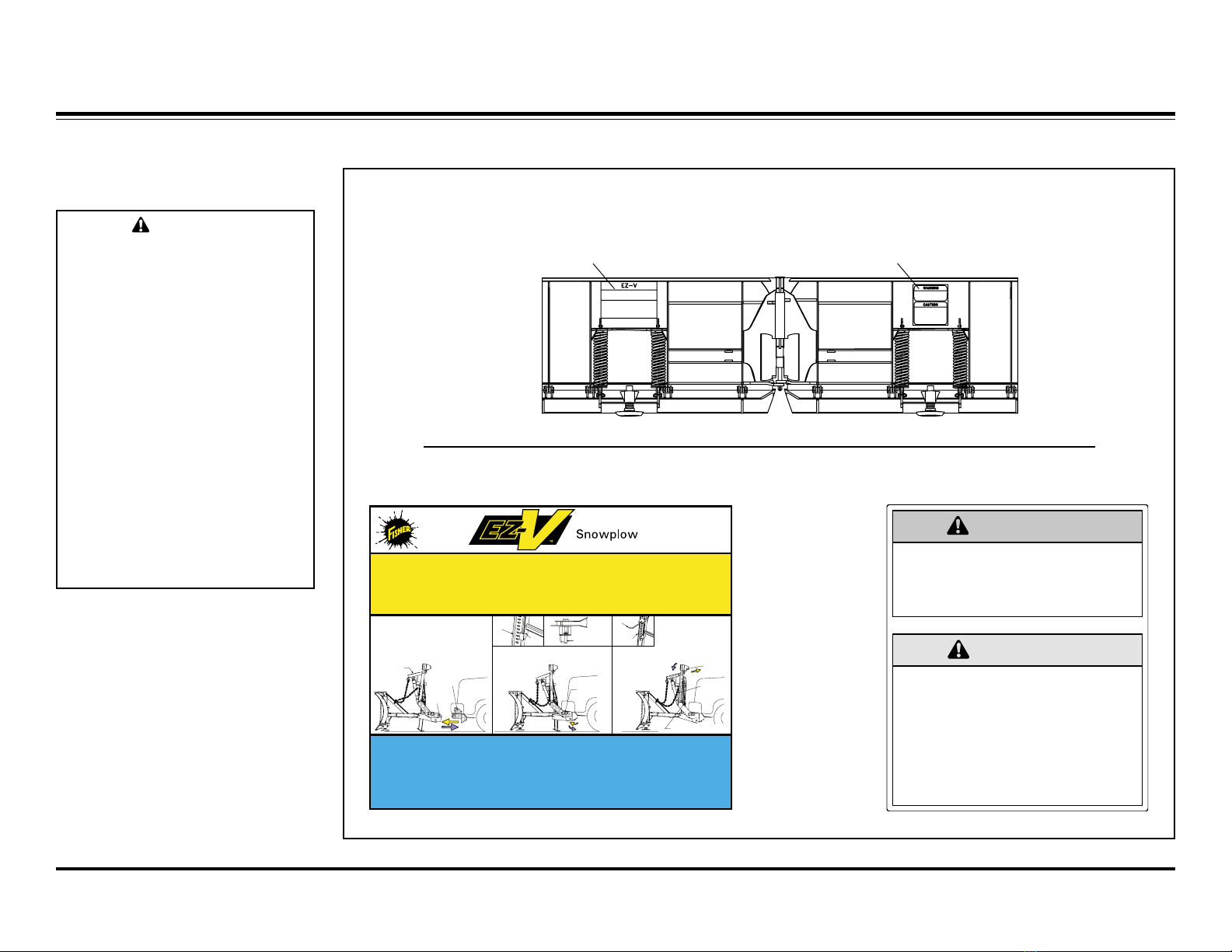
Please bec me familiar with the Safety and Instructi n labels n the back f the blade!
Safety LabelInstruction Label
Instruction Label Safety Label
Pushplate
Attachment
Arm
Jack
Leg
Jack
Stand
Jack Lever
Jack Leg
Connecting Pin
Headgear
Carrying
Chain
Jack Leg (Raised)
Connecting
Pin Withdrawn
Lift Arm
MOUNTING PLOW
U.S. Patent
4,280,062, 4,999,935
5,353,530, 5,420,480
and other patents pending
1. Drive vehicle forward fully engaging
pushplates into attachment arms. 2. Twist connecting pin to release tension.
3. Remove electrical covers on vehicle.
4. Attach electrical connector to
corresponding connector on vehicle.
5. Repeat these steps on passenger side
of vehicle.
6. Release carrying chain and reattach it
leaving plenty of slack.
7. Push headgear upward toward vehicle
until connecting pins snap in place.
8. Pull jack lever outward and raise the
jack leg.
PLOW REMOVAL
1. Position blade in the straight mode
before removing.
2. Place control in Lower mode.
3. Push lift arm down.
4. Pull jack lever outward. ack leg will
adjust to proper height.
5. Disconnect electrical connectors and
cover with protective covers.
6. Insert release rod in lowest possible slot
on jack leg above A-frame.
7. Push down on release rod as you pull
and twist connecting pin.
8. Repeat these steps on passenger side
of vehicle.
9. Remove slack from carrying chain and
reattach.
10. Back vehicle away from plow.
21763
WARNING
CAUTION
LOWER BLADE WHEN VEHICLE IS PARKED.
REMOVE BLADE ASSEMBLY BEFORE PLACINGVEHICLE
ON HOIST.
DO NOT EXCEED GVWR OR GAWR INCLUDING BLADE
AND BALLAST.
READ OWNER'S MANUAL BEFORE OPERATING OR
SERVICING SNOWPLOW.
TRANSPORT SPEED SHOULD NOT EXCEED 45 MPH.
REDUCE SPEED UNDER ADVERSETRAVEL
CONDITIONS.
PLOWING SPEED SHOULD NOT EXCEED 10 MPH.
REMOVE SLACK FROM CARRYING CHAIN BEFORE
TRAVELING.
SEEYOUR FISHER OUTLET FOR APPLICATION
RECOMMENDATIONS.
21793
CAUTION
Batteries normally produce
explosive gases which can
cause personal injury.
Therefore, do not allow flames,
sparks or lit tobacco to come
near the battery. When
charging or working near a
battery, always cover your face
and protect your eyes, and also
provide ventilation.
Batteries contain sulfuric acid
which burns skin, eyes and
clothing.
Disconnect the battery before
removing or replacing any
electrical components.
BATTERY SAFETY

No. 21856 July 1997
5
T ls
TOOLS R QUIR D PRODUCT SP CIFICATIONS
V-Pl w Specificati ns
Electrical System approximate
values:
Solenoid Coil Resistance =
7 Ohms at room temperature
Solenoid Coil Amp. Draw =
1.5 Amp.
Motor Relay Coil Resistance =
16 - 17 Ohms
Motor Relay Amp. Draw =
0.7 Amp.
Maximum Motor Amp. Draw =
190 Amp.
Headlamp Relay Coil
Resistance = 106 Ohms
Headlamp Relay Amp Draw =
0.1 Amp.
Fuse Size
Harness 10 Amp.
(10AFB 3AG)
Circuit Board (2) 5 Amp.
(5AFB SMD)
Mechanical
Fastener Tor ue for :
Pump Bolts = 150160 IN-LB
Motor Bolts = 3040 IN-LB
Reservoir Bolts = 1520 IN-LB
Cartridge Tor ue = 120 IN-LB
Check Valve Tor ue =
120 IN-LB
Coil Nut Tor ue = 4860 IN-LB
Secondary Manifold Block
Assembly Bolt Tor ue =
108 IN-LB
Angle Cylinder
Piston Locknut Tor ue =
100-120 FT-LB
Gland Nut Tor ue =
150-180 FT-LB.
Hydraulic System
Relief valve settings
Pump relief valve = 1750 PSI.
2 1/2 - 2 3/4 turns CCW from
fully seated
Primary relief valve = 3000 PSI.
1 1/2 - 1 3/4 turns CCW from
fully seated
Secondary relief valve = 3500
PSI. 1 1/4 - 1 1/2 turns CCW
from fully seated
Fluid CapacityHydraulic Oil
Unit Reservoir = 1 3/4 Quarts
System Total = 2 1/2 Quarts
Hydraulic Oil
FISHER® High Performance
Fluid to -25°F (-32°C)
Solenoid Valve Spool Travel = 0.07"
for three- and four-way valves
For servicing the electrical and
hydraulic system
Re uired:
Miniature Needle Nose Pliers
Flat Screwdriver
Combination Wrenches: 3/8",
7/16" (2), 1/2", 11/16", 3/4", 7/8"
1/4" Socket or Nut driver
Test Light
Recommended :
Combination Wrenches:
1-1/16", 1-1/8"
Deep Sockets: 11/16", 7/8",
1-1/16", 1-1/8"
Tor ue Wrench ( IN-LB )
Volt/Ohm Meter
Pencil Magnet
3000 PSI Pressure Gauge
For replacing trip springs :
Removable Spring Tool
available from your Fisher
outlet
CAUTION
Do not mix different types of
hydraulic fluid. Some fluids are
not compatible and may cause
performance problems and
product damage.
No. 21856 July 1997
6
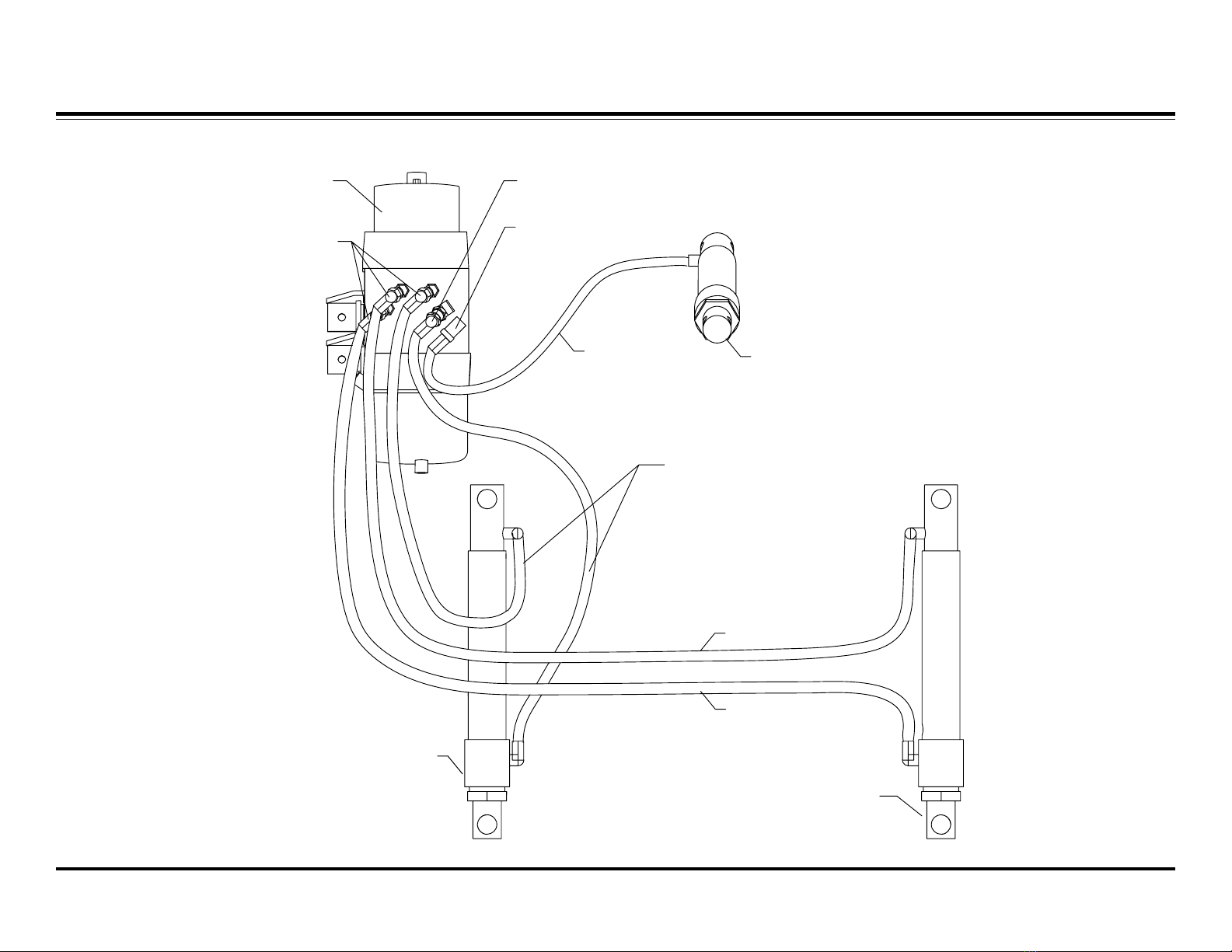
PLOW SIDE
Passenger-Side
Angle Cylinder
(Right Side)
45° Swivel
45° Street Elbow and
Straight Swivel
90° Street Elbow
and Straight Swivel
18" Hose
36" Hose
34" Hose
36" Hoses
Hydraulic
Unit
Driver-Side
Angle Cylinder
(Left Side)
Lift Cylinder
HOS ROUTING
No. 21856 July 1997
7
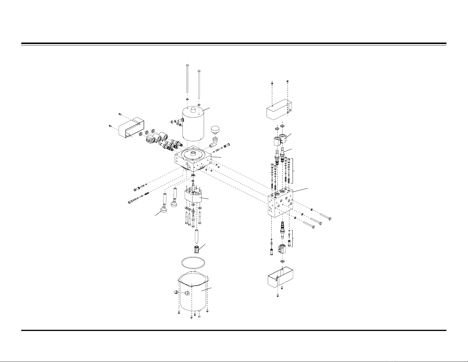
HYDRAULIC UNIT PARTS DIAGRAM
Motor
Primary Valve
Block
Solenoid Valve Coil
Solenoid Valve Cartridge
Relief Valve
Pilot Operated
Check Valve
Reservoir
Pump Filter
Pump
Oil Return Line
Secondary Valve Block

No. 21856 July 1997
8
SOL NOID CARTRIDG VALV ID NTIFICATION AND LOCATION
Solenoid Cartridge
Valve—S1
Solenoid Cartridge
Valve—S6
Solenoid Cartridge
Valve—S4
Solenoid Cartridge
Valve—S5
Solenoid Cartridge
Valve—S3
Solenoid Cartridge
Valve—S2

No. 21856 July 1997
9
R LI F VALV ID NTIFICATION AND LOCATION
RIGHT SECONDARY
RELIEF VALVE
RELIEF VALVE
RIGHT PRIMARY
RELIEF VALVE
LEFT SECONDARY
LEFT PRIMARY
RELIEF VALVE
PUMP RELIEF VALVE
(Passenger Side)
(Passenger Side)
(Driver Side)
(Driver Side)

No. 21856 July 1997
10
PILOT OP RAT D CH CK VALV ID NTIFICATION AND LOCATION
CHECK VALVE C
CHECK VALVE D
CHECK VALVE B
PILOT OPERATED (P/O)
PILOT OPERATED (P/O)
PILOT OPERATED (P/O)
PILOT
OPERATED (P/O)
CHECK VALVE A
No. 21856 July 1997
11
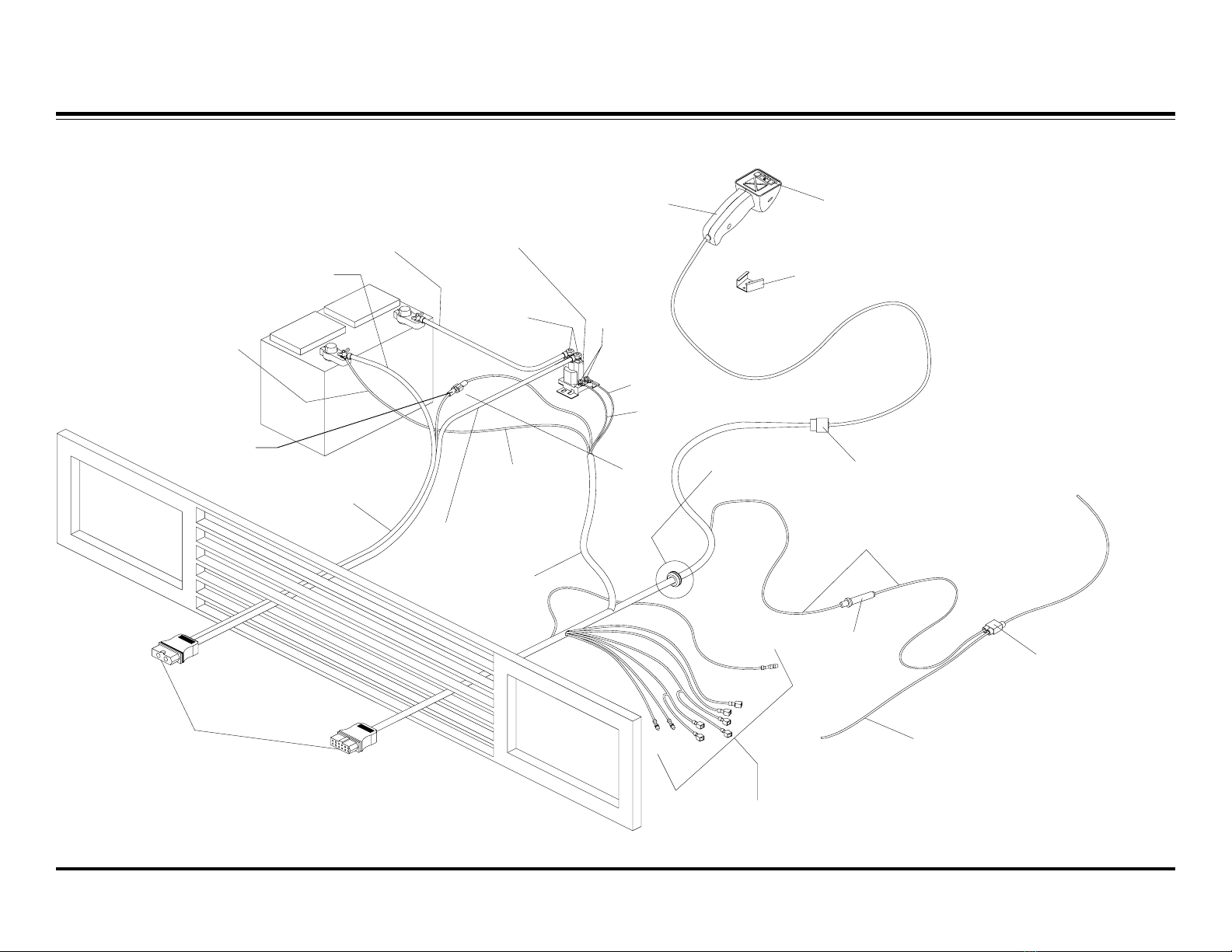
V HICL HARN SS AND V HICL CABL LOCATION
MODE
L
S
/
P
LOWER
C
FLT
R
/
V
E
E
RAISE
PWR
Control ON/OFF
Switch
Control
Bracket
14-pin Connector
(in-cab)
Red Wire
Fuse
Holder Self-Stripping
Connector (Blue)
Vehicle Wire Controlled
by Ignition Switch
Wires to
Headlamp Relays
Grille
Connectors
Vehicle Cable
Assembly
Black Wire
Red Wire
Vehicle
Harness
To Negative
Battery Terminal
22" Red Cable
Secondary
(Large)
Terminals
Motor Relay
Primary
(Small)
Terminals
Brown/Red
Orange/
Black
Firewall
Grommet
+
-
Small Red
Wire
3-pin
12-pin
Faston
Connector
Brown/Green
No. 21856 July 1997
12
WARNING
OP RATING TH SNOWPLOW
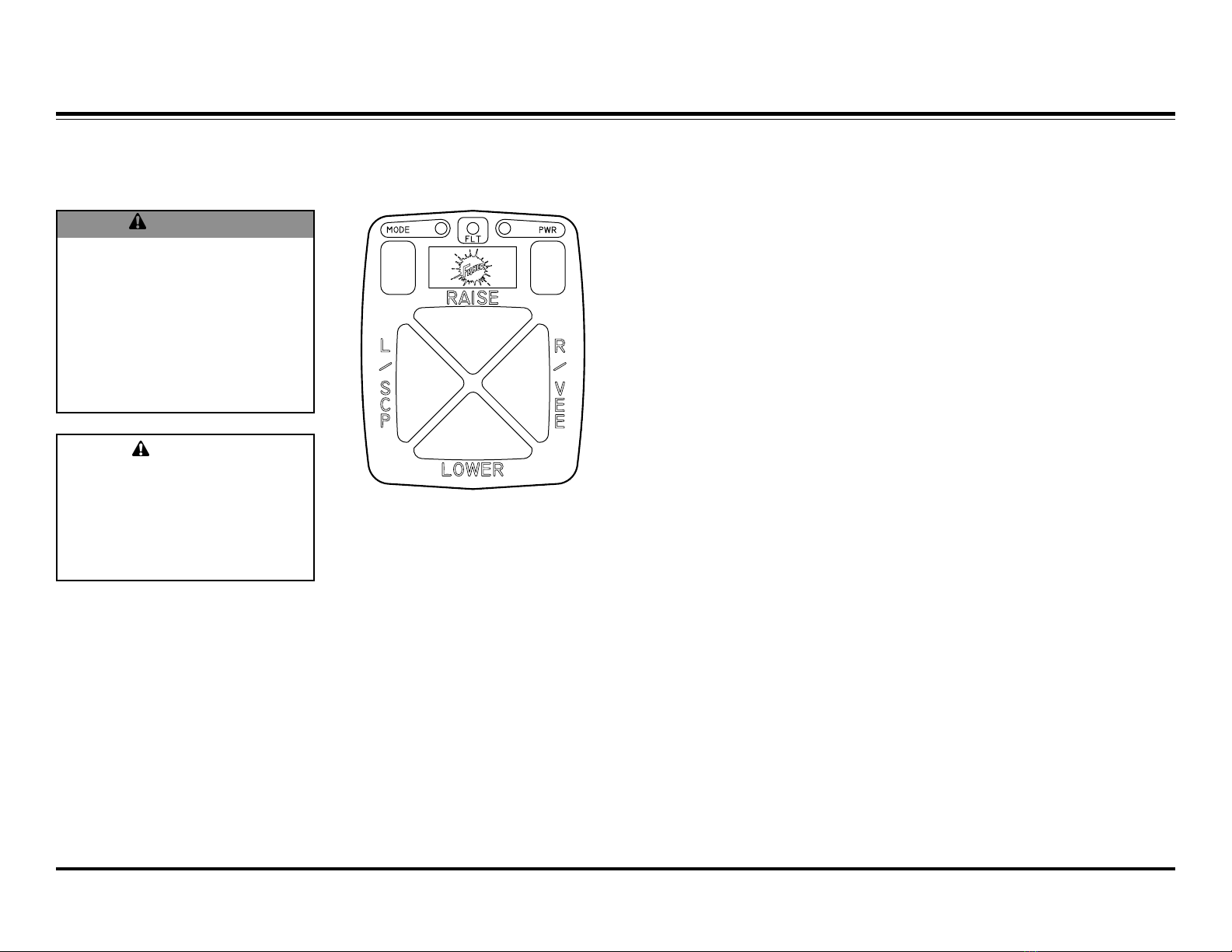
Fish-Stik Hand-Held C ntr l
The driver shall keep
bystanders clear of the blade
when it is being raised, lowered
or angled. Do not stand
between the vehicle and the
blade, or within 8 feet of a
moving blade. A moving or
falling blade could cause
personal injury.
CAUTION
To prevent accidental
movement of the blade, always
turn the ON/OFF switch to OFF
whenever the snowplow is not
in use. The control indicator
light will turn off.
Functi n Time Outs
All control functions, except for
LOWER, automatically time out
stopafter a period of time. This is to
help prolong the battery charge. The
time-out period for the RAISE
function is 2.5 seconds, while all
others are 4.25 seconds.
The control will automatically turn off
after being idle for 20 minutes.
2. Press the PWR button on the
control. The control indicator
light will glow red indicating the
control is on. The control
indicator light will glow red
whenever the control ON/OFF
switch and the vehicle ignition
switch are both ON and the
plow plugs are connected to
the grill connectors.
Sm th St p
The control automatically allows the
blade to coast to a stop. This results
in smoother operation, reduces the
shock to the hydraulic system and
increases hose and valve life.
1. Turn the vehicle ignition switch
to the ON or the ACCESSORY
position.

No. 21856 July 1997
13
Straight Blade M deDefault
Vee/Sc p M de
Quickly press and release the MODE
key to put the control into the vee/
scoop mode. The MODE lamp, near
the upper left corner of the keypad,
will light. Quickly pressing and
releasing the MODE key will toggle
the control between straight blade
mode and vee/scoop mode.
The functions shown at right are
performed in the vee/scoop mode:
OP RATING TH SNOWPLOW
The control automatically defaults to
the straight blade mode when turned
on. The MODE lamp, near the MODE
key in the upper left corner of the
keypad, will not be illuminated or
flashing when the control is in the
straight blade mode.
The functions shown at right are
performed in the straight blade mode:
Button Description of Operation
Raise Press this button to raise the plow and to cancel the float mode.
NOTE: Plow will automatically stop raising after 2.5 seconds. To resume raising the plow, release the button
and press again.
Lower Press this button to lower the plow. NOTE: After reaching the desired height, release the button. Holding the
button down for more than 3/4 second will activate the float mode, indicated by green FLT lamp.
L / SCP Press this button to angle both wings to the left.
R / VEE Press this button to angle both wings to the right.
Button Description of Operation
Raise Press this button to raise the plow and to cancel the float mode.
NOTE: Plow will automatically stop raising after 2.5 seconds. To resume raising the plow, release the button
and press again.
Lower Press this button to lower the plow. NOTE: After reaching the desired height, release the button. Holding the
button down for more than 3/4 second will activate the float mode, indicated by green FLT lamp.
L / SCP Press this button to extend both wings to the scoop position.
R / VEE Press this button to retract both wings to the vee position.

No. 21856 July 1997
14
OP RATING TH SNOWPLOW
Wing M de
To put the control into the wing mode,
press and hold the MODE key for
about two seconds until the MODE
lamp near the upper left corner of the
keypad is flashing. The L / SCP and
R / VEE keys are used to activate the
four functions of the wing mode. The
RAISE and LOWER keys function the
same as in the other modes.
The functions shown at right are
performed in the wing mode:
Button Description of Operation
Raise Press this button to raise the plow and to cancel the float mode.
NOTE: Plow will automatically stop raising after 2.5 seconds. To resume raising the plow, release the
button and press again.
Lower Press this button to lower the plow. NOTE: After reaching the desired height, release the button.
Holding the button down for more than 3/4 second will activate the float mode, indicated by green FLT
lamp.
L / SCP Pressing this button the first time will retract the left wing.
Pressing this button the next time will extend the left wing.
R / VEE Pressing this button the first time will retract the right wing.
Pressing this button the next time will extend the right wing.

No. 21856 July 1997
15
TH ORY OF OP RATION
Pl w Hydraulics
The EZ-V snowplow
hydraulic system performs
10 blade movement
functions.
All functions re uire the
vehicle ignition (key) switch to be in
the run or accessory position and the
power to be activated on the
snowplow cab control.
Nine of the ten hydraulic functions
re uire energizing the electric motor,
shifting of solenoid cartridge spools
or activating p/o check valves. The
tenth function, lower, does not
energize the motor but re uires
shifting of solenoid cartridge spools.
Operation of Electrical Circuit:
The electrical drive circuit that is used
for the EZ-V snowplow hydraulics is
defined as a low side drive system.
MOVEMENT
BLADE RAISE LOWER
ANGLE
RIGHT
ANGLE
LEFT RIGHT
EXTEND
RIGHT
RETRACT LEFT
RETRACT SCOOP VEE
(DEFAULT)
STRAIGHT BLADE
R/VEE L/SCP R/VEE *
R/VEE *
WING
CONTROLLER MODE
CONTROLLER BUTTON
V / SCOOP
L/SCP * L/SCP R/VEE RAISE LOWER
ALL ALL
EXTEND
LEFT
L/SCP *
Low side drive provides a common
live hot (12V) to all of the loads (coils,
relays, etc.). When the cab control is
activated, the ground path is closed
to complete the circuit, energizing the
selected coils and/or relay. The
current flow through the coils
produces a magnetic field which
shifts the spools in the cartridges.
The cartridges direct the fluid flow to
the appropriate passages to produce
the selected blade movement
function. Current flow also energizes
the motor relay, closing the motor
relay contacts connecting the motor
to the battery through heavy electrical
cables. The heavy cables carry a
large current flow which energizes the
motor, which in-turn rotates the
internal pump and creates fluid flow.
(Motor relay does not energize in
lower function).
Testing Low Side Drive Systems:
To test a low side drive system,
connect the negative lead of the test
instrument (volt meter) to ground and
the positive lead to the negative side
of the load (coil, relay, etc.). A
reading of 12 volts should be
indicated when the load is not
activated. A reading of near 0 volts
when load is activated.

No. 21856 July 1997
16
TH ORY OF OP RATION
Pl w Headlamps
The headlamp circuit operates using
a high side drive system. High side
drive provides a hot 12V source to
activate the loads (coils, relays, etc.)
that share a common ground. The
headlamp switching circuit uses two
single pole double throw (SPDT)
relays. When combined with the
snowplow plug-in headlamp harness
and the vehicle harness, the relays
will automatically switch between
plow and vehicle headlamps as the
plow plugs are connected and
disconnected.
The vehicle harness has a brown
wire that is spliced into the vehicle
park lamp circuit. This wire feeds the
plow park lamps through the grill
connector and also powers the coils
of both relays. The other terminal of
the relay coils is connected to the
black/orange ground wire which also
goes to the grill connector. When
both the plow and battery cable plugs
are connected to the grill connectors,
a ground is completed for the relay
coil. When the vehicle park lamps
are turned on and the plugs are
connected, the relay coils will be
activated. This causes the relay
contacts to switch from the normally
closed contacts to the normally open
contacts. The normally closed
contacts power the vehicle
headlamps. The normally open
contacts power the plow headlamps.
Refer to the Headlamp Test Diagram
in the Troubleshooting Guide.
It should be noted that:
The relay with the yellow,
orange and black wires
operates the low beam
headlamps.
The relay with the green, red
and white wires operates the
high beam headlamps.
The parking lamp circuit
provides power to both relays
at the same time.
Both plow plugs (12 pin and
battery cable) need to be
connected and the headlamp
switch must be on for the
relays to activate.
Daytime Running Lights
An additional fused pink wire is used
in place of the brown park circuit wire
to introduce power to the light relays.
The pink wire is connected to a circuit
controlled by the vehicle ignition
switch. When the vehicle ignition is
on and the grill connector plugs are
connected the relay coils will be
activated. This allows the DRLs to be
switched to the plow lights when the
vehicle headlamp switch is off. DRLs
use the same circuit as the regular
headlamps.
Testing High Side Drive Systems:
Connect the negative lead of the test
instrument (voltmeter) to ground and
positive lead to the positive side of
the load. A reading of 12 volts should
be indicated when the load is
activated; zero volts when load is not
activated.

No. 21856 July 1997
17
HYDRAULIC AND L CTRICAL SCH MATICS
The following section contains
hydraulic and electrical schematics to
help explain how the hydraulic unit
performs the different functions. A
schematic is an abstract drawing
showing the purpose of each of the
components in the system. Each
component is represented by a
graphical symbol. The hydraulic and
electrical legends list and describe
each of the symbols used in the
schematics for this guide.
The first two schematics show a
general overview of the complete
hydraulic and electrical systems. The
remainder of the schematics have
been altered to highlight flow of
hydraulic oil and electrical current for
each function the hydraulic unit
performs or flow of electrical current
for the snowplow and vehicle lights.
Bold lines represent the circuit
being activated only.
Shaded components are either
activated or shifted from their
normal position.
FILTER,STRAINER
DIFFUSER
COMPONENT ENCLOSURE
ELECTRIC MOTOR
CYLINDER
FIXED DISPLACEMENT
HYDRAULIC PUMP
BELOW FLUID LEVEL
LINE, TO RESERVOIR
LINES CROSSING
LINES OINING
LINE, PILOT (FOR CONTROL)
LINE, WORKING (MAIN)
FLOW, DIRECTION OF CHECK VALVE
SOLENOID, SINGLE WINDING
SPRING
PRESSURE RELIEF
VALVE, AD USTABLE
AD USTABLE-
NON-COMPENSATED
VALVE, FLOW CONTROL,
VALVE, TWO POSITION
TWO CONNECTION
(TWO-WAY)
VALVE, TWO POSITION
THREE CONNECTION
(THREE-WAY)
VALVE, TWO POSITION
FOUR CONNECTION
(FOUR-WAY)
HYDRAULIC LEGEND
CROSSING WIRE
WIRE SPLICE
FUSE
SOLENOID
CIRCUIT GROUND
MOTOR RELAY
BATTERY
MOTOR
ELECTRICAL LEGEND
HYDRAULIC FLUID
IN LINE CONNECTOR
WIRE CONTINUES
ELSEWHERE
LIGHT
PILOT OPERATED (P/O)
COMPONENT ENCLOSURE
No. 21856 July 1997
18
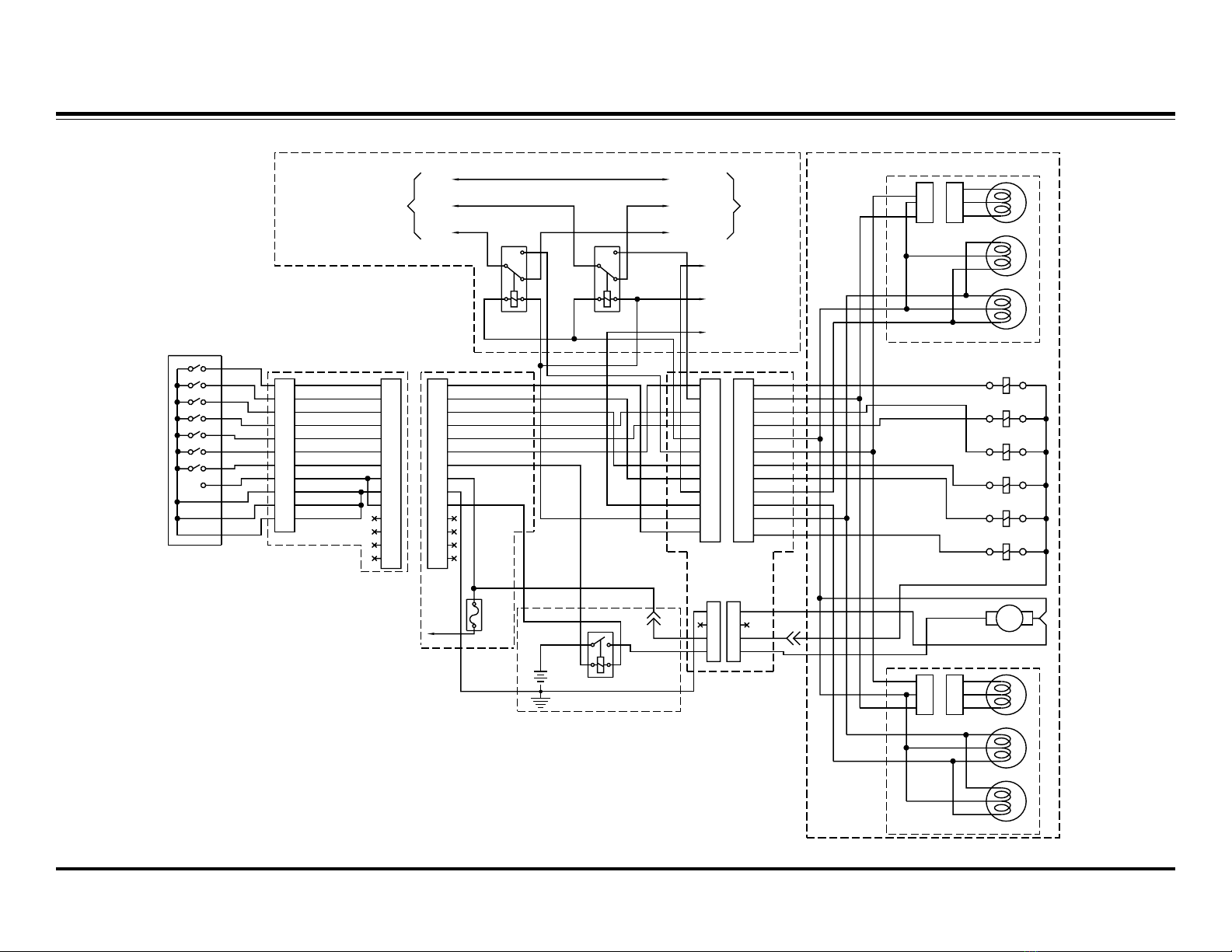
L CTRICAL SCH MATIC
BLK/ORN
HIGH BEAM LOW BEAM
GND
LOW
HIGH GRN
YEL
BLU
BLK
ORN
RED
TO LEFT TURN SIG
M BULLET
TO PARK LAMP
M BULLET
TO RIGHT TURN SIG
M BULLET
GRY
TO VEHICLE
HEADLIGHT CONNECTOR HARNESS
HEADLAMP
COMPONENTS LOCATED FRONT LEFT OF VEHICLE
LEFT SIDE PLOW LAMP
TURN SIG
TURN SIG
HEADLIGHT
CON3 CON3
T
P
T
P
RIGHT SIDE PLOW LAMP
L
H
GRY
PLOW ASSEMBLY
*
CIRCUIT BOARD
OF PRINTED
REPRESENTATION
11
*
8
10
9
7
6
4
5
3
CONTROL
1
2
ORN
11
10
9
7
8
5
6
TAN
BLK
BRN
GRN
RED
BLU
COIL CORD HARNESS
4
3
1
2
WHT
GRY
YEL
VIO
13
14
ORN/BLK
RED
14
13
12V BATTERY
LOCATED AT VEHICLE FRONT RIGHT
#6 RED
MTR RLY
10AFB
LOCATED UNDER DASH
BLU/ORN
LT BLU/ORN
BLK/WHT
LT BLU
LT GRN
BRN/RED
WHT/YEL
11
12
9
10
7
8
5
6
3
4
2
1
12
11
10
9
7
8
5
6
3
4
2
1
RED
BRN/GRN
BRN
BRN
#6 BLK
#6 RED
FASTON
VIO
BLK/ORN
BRN
BLK
WHT
LOCATED AT GRILLE
VIO
WHT
PUMP MOTOR
#6 RED
#6 BLK
+M
-
RED
BLK/ORN
S6 SOLENOID
LT BLU/ORN
BLU/ORN
BLK/WHT
WHT/YEL
LT BLU
LT GRN
IGNITION
BLK (HIGH)
ORN (LOW)
BLU (GND)
1
8
12
11
9
10
4
6
7
5
2
3
8
12
11
9
10
4
6
7
5
2
3
1
4
2
3
11
2
3
4
1
2
33
2
1
L
TURN SIG
CON3
3
CON3
3
TURN SIG
T
P
HEADLIGHT
T
P
2
1
2
1H
S5 SOLENOID
S4 SOLENOID
S3 SOLENOID
S2 SOLENOID
S1 SOLENOID
TO
No. 21856 July 1997
19
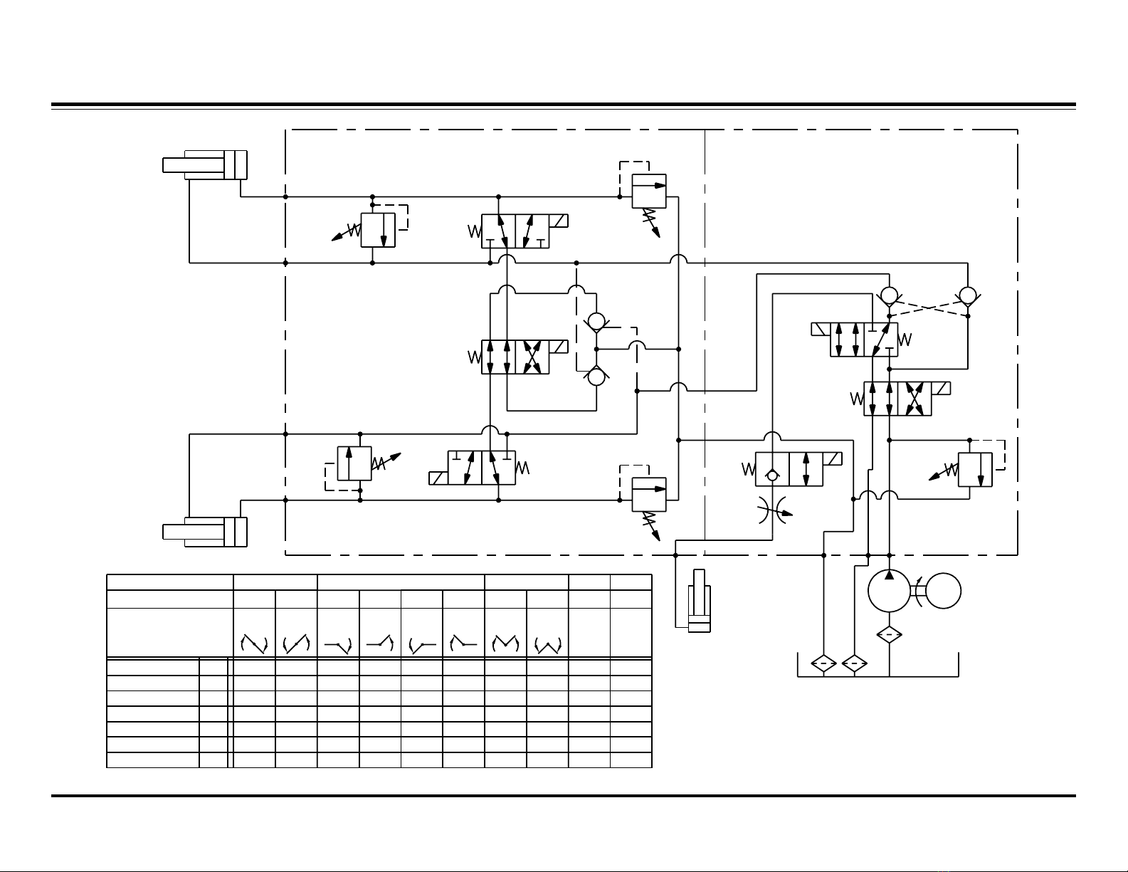
HYDRAULIC SCH MATIC
M
LEFT
RIGHT
3000 PSI
3000 PSI
3500 PSI
3500 PSI
1750 PSI
S6
S3
S1
S5
S4
S2
(C)
(D)
(A) (B)
LIFT
RELIEF VALVE
SECONDARY
RELIEF VALVE
SECONDARY
SECONDARY BLOCK ASSY. PRIMARY BLOCK ASSY.
VALVE
RELIEF
PRIMARY
PRIMARY
RELIEF
VALVE
VALVE
RELIEF
PUMP
MOTOR
SV08-2004
SV08-40
SV08-43
SV08-40
SV08-30 S6
S5
S3
S2
S1
M
S4
SV08-30
ON
ON
ON
ON
ON ON
ON
ON ON
ON
ON
ON
ON
ON
ON ON
ON
ON ON
ON
ON
MOVEMENT
BLADE
RAISE LOWER
ANGLE
RIGHT
ANGLE
LEFT
RIGHT
EXTEND
RIGHT
RETRACT
LEFT
RETRACT SCOOP VEE
(DEFAULT)
STRAIGHT BLADE
R/VEE L/SCP R/VEE *
R/VEE *
WING
CONTROLLER MODE
CONTROLLER BUTTON
V / SCOOP
L/SCP * L/SCP R/VEE RAISE LOWER
ALL ALL
* NOTE - SEE BLADE MOVEMENT TEXT
FOR BUTTON OPERATION
EXTEND
LEFT
L/SCP *
ON
ON
ON
P/O CHECK
VALVE
P/O
CHECK
VALVE
P/O
CHECK
VALVE
P/O
CHECK
VALVE
No. 21856 July 1997
20
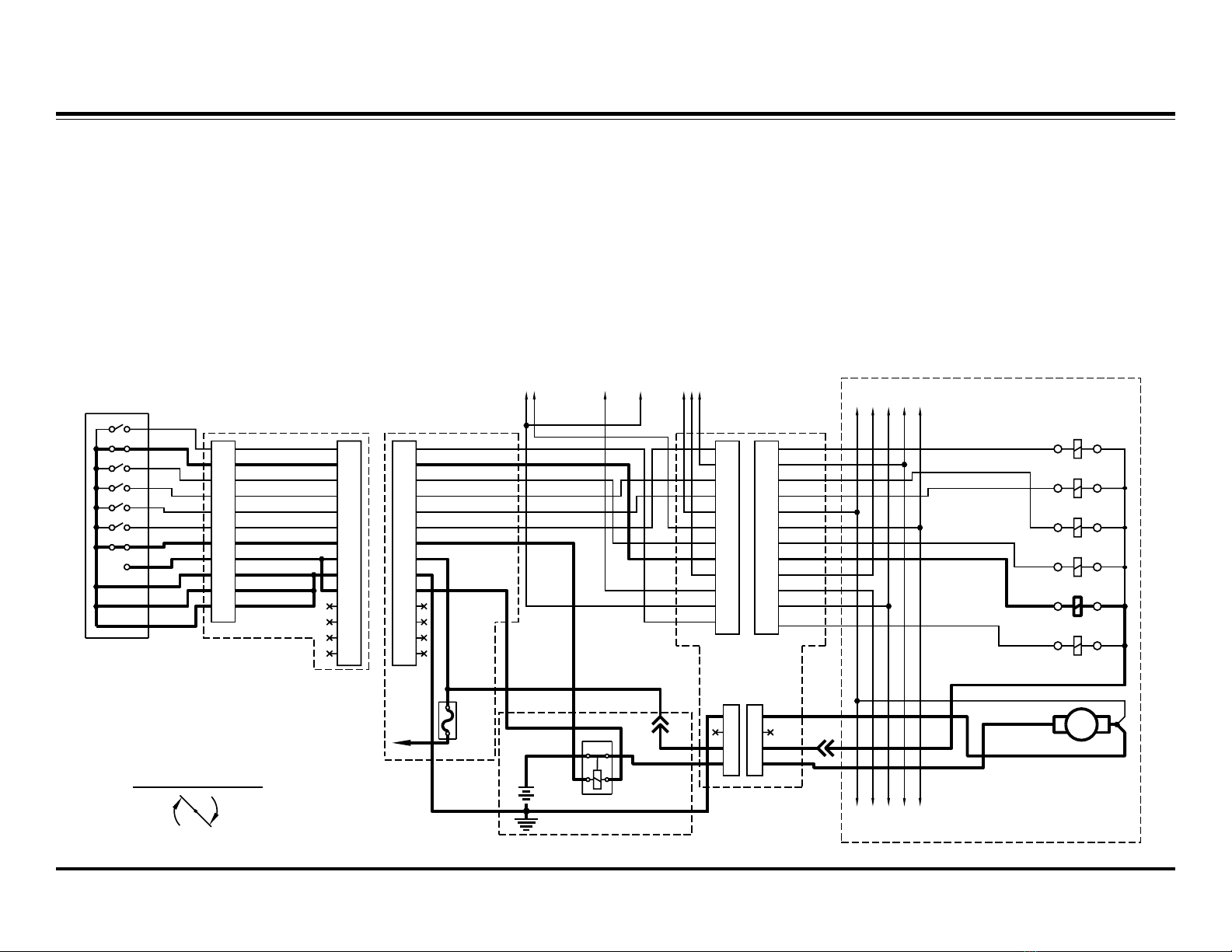
ANGL RIGHT L CTRICAL
COMPONENTS LOCATED FRONT LEFT OF VEHICLE
LEFT SIDE PLOW LAMP
RIGHT SIDE PLOW LAMP
GRY
PLOW ASSEMBLY
*
CIRCUIT BOARD
OF PRINTED
REPRESENTATION
11
*
8
10
9
7
6
4
5
3
CONTROL
1
2
ORN
11
10
9
7
8
5
6
TAN
BLK
BRN
GRN
RED
BLU
COIL CORD HARNESS
4
3
1
2
WHT
GRY
YEL
VIO
13
14
ORN/BLK
RED
14
13
12V BATTERY
LOCATED AT VEHICLE FRONT RIGHT
#6 RED
MTR RLY
10AFB
LOCATED UNDER DASH
BLU/ORN
LT BLU/ORN
BLK/WHT
LT BLU
LT GRN
BRN/RED
WHT/YEL
11
12
9
10
7
8
5
6
3
4
2
1
12
11
10
9
7
8
5
6
3
4
2
1
RED
BRN/GRN
BRN
BRN
#6 BLK
#6 RED
FASTON
VIO
BLK/ORN
BRN
BLK
WHT
LOCATED AT GRILLE
VIO
WHT
PUMP MOTOR
#6 RED
#6 BLK
+M
-
RED
BLK/ORN
S6 SOLENOID
LT BLU/ORN
BLU/ORN
BLK/WHT
WHT/YEL
LT BLU
LT GRN
IGNITION
1
8
12
11
9
10
4
6
7
5
2
3
8
12
11
9
10
4
6
7
5
2
3
1
4
2
3
11
2
3
4
S5 SOLENOID
S4 SOLENOID
S3 SOLENOID
S2 SOLENOID
S1 SOLENOID
BLADE MOVEMENT
ANGLE RIGHT
Blade Movement: Angle Right
Controller Mode: Straight Blade
Mode (Default)
Controller Button: R/VEE
System Response:
1) By pressing the controller button,
the circuit board within the cab
control completes the ground
path for the electrical circuit.
2) Electrical current flows through
the motor relay, activating the
pump motor, and solenoid
cartridge valve S5, shifting its
spool.
3) Hydraulic oil from the pump flows
through solenoid cartridge valve
S2, P/O check valve (B) and into
the rod end of the right cylinder
causing it to retract.
4) Pressure within the hydraulic
circuit causes P/O check valves
(A) & (D) to open.
5) The retracting right cylinder
pushes the hydraulic oil out of its
base end, through solenoid
cartridge valves S6 & S5 & S4
and into the base end of the left
cylinder causing it to extend.
6) The extending left cylinder
pushes the hydraulic oil out of its
rod end, through P/O check valve
(A), solenoid cartridge valves S3
& S2 and back to the reservoir.
Table of contents
Other Fisher Engineering Automobile Accessories manuals


