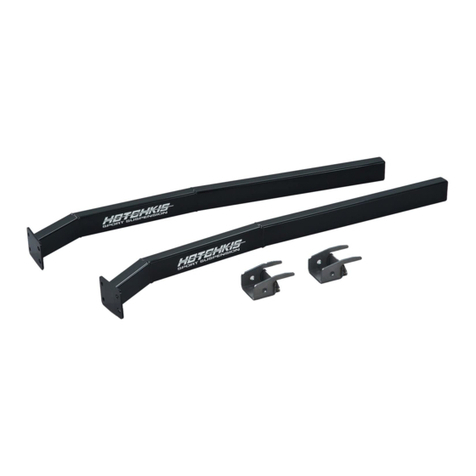
Hotchkis 2207C User manual

1967-1969 GM F Body
Hotchkis Performance LLC. 1
2207CAnti-RollBarInstallationInstructions
Thank you for your purchase of this Hotchkis Performance product. Your stabilizer bar set was
designed with the performance and durability you’ve come to expect from Hotchkis
Performance.
Note: Please read the entire installation instructions before starting. Having the right tools
will ensure a smooth install process.
FRONTBARINSTALLATION
Removing Stock Anti-Roll Bar
1F. Support the vehicle on jack stands, and remove the front wheels.
2F. Look at the current bar installation and note the position of the anti-sway bar.

1967-1969 GM F Body
Hotchkis Performance LLC. 2
3F. Loosen, but do not remove the front bushing bolts.
4F. Remove the endlinks from the sway bar and lower control arms.

1967-1969 GM F Body
Hotchkis Performance LLC. 3
5F. Completely remove the bolts from the frame. Retain these bolts for reinstallation.
6F. Turn the steering all the way to the LEFT and remove the stock bar through the
DRIVER side wheel well. Observe the following pictures for the removal procedure.

1967-1969 GM F Body
Hotchkis Performance LLC. 4

1967-1969 GM F Body
Hotchkis Performance LLC. 5
InstallingNewHotchkisAnti-RollBar
7F. Here’s the fun part. The Hotchkis bar has a larger tube diameter, so installing it may
take some patience. Please follow the pictures below. They should show you a step-
by-step way to install the bar.

1967-1969 GM F Body
Hotchkis Performance LLC. 6
At this point the sway bar will need a little force to get into position. Take your trusty dead
blow hammer and hit the anti-roll bar end as shown in the picture below. It won’t take too
much to pop it into place.
Once the anti-roll bar end is above the lower control arm, you can easily slide it into position.

1967-1969 GM F Body
Hotchkis Performance LLC. 7
8F. Once the bar is in place, install the new endlinks but do not tighten them completely.
9F. Using the included white silicon grease, lube the inside of the new 1 ¼” front bushings.
NOTE: the grease can be cleaned up with WD-40

1967-1969 GM F Body
Hotchkis Performance LLC. 8
10F. Install the bushing on the new Hotchkis bar. Make sure the split on the bushing faces
the front when the bar is installed in the vehicle. Look at the placement of the original
stock bushings on the stock bar for guidance.
11F. Place the greasable bracket over top the bushing and secure them with the stock bolts.
You may fully tighten these bolts at this time.

1967-1969 GM F Body
Hotchkis Performance LLC. 9
12F. It is best to tighten the endlinks with the suspension at ride height. To achieve this,
simply reinstall the wheels and drive the car onto some floor ramps. These can be
found at your local auto store. Now, with the car at ride height and on the floor ramps
you can crawl underneath the car and fully tighten the endlinks. Tighten the endlinks
until the bushings are squeezed just enough that their diameter is just larger than the
supporting washer.
You are now finished installing your new Hotchkis Anti-Roll bar.

1967-1969 GM F Body
Hotchkis Performance LLC. 10
1R. Remove the lower rear seat cushion. If the cushion won’t pull up easily, use a long
screwdriver to push and release the small bar that is clipped in the bracket. Remove
the two bolts that hold the back part of the seat to the body and lift the upper cushion
to remove it from the vehicle. This will allow you to access the floor pans.
2R. Jack up the vehicle and properly support with jack stands or lift jacks. Make sure the
rear end is supported with the vehicle’s load on the leaf springs. This is to ensure you
install the rear bar in the proper position.
3R. Take the 7/8” bushings and grease the inner surface with the included white silicon
grease.
InstallationofHotchkisRearSwayBar

1967-1969 GM F Body
Hotchkis Performance LLC. 11
4R. Install the bushings on the bar. (4) Place the bracket over top of the bushing. (5)
5R. After you determine there’s enough clearance for the bar, note the approximate
location of the sway bar axle bushings.
6R. Take a screwdriver and carefully pry up the brake line to allow the U-Bolt to drop down
over the axle. (7)

1967-1969 GM F Body
Hotchkis Performance LLC. 12
7R. Install the U-Bolts on the axle and slip the axle bracket over the U-Bolt on the bottom
side of the axle. Use masking or duct tape to secure them. Place the sway bar
assembly under the axle and slip the U-bolt legs through the sway bar brackets. Place
washers and nylock nuts on the U-Bolt. Snugly fasten the nylock nuts a bit, but do not
fully tighten at this time.

1967-1969 GM F Body
Hotchkis Performance LLC. 13
8R. Remove the screw and clip that holds the fuel line located on the frame rail of the
passenger side to allow for the chassis brace to slide into place.
9R. Lift chassis brace up and over the back side of the rear axle and position it up against
the body pan and chassis as shown below.

1967-1969 GM F Body
Hotchkis Performance LLC. 14

1967-1969 GM F Body
Hotchkis Performance LLC. 15
NOTE:
We have noticed on rare occasions that the brace is too narrow on some chassis’. If
there is more than an 1/8” of gap between the brace and the frame rails, then please
use the special spacer shims (part # 23490019) included in your kit to rectify the
tolerance issue.
10R. Once you have the chassis brace in place, mark the spots where you will drill the holes
to secure the brace. Do this on both sides.

1967-1969 GM F Body
Hotchkis Performance LLC. 16
11R. Remove the chassis brace and using a 7/16” drill bit, drill the 4 holes that you just
marked.
12R. Place chassis brace back into place and mark the remaining 4 holes for drilling as shown
below. After marking the holes, remove brace and using a 7/16” drill bit, drill the holes.

1967-1969 GM F Body
Hotchkis Performance LLC. 17
13R. Using the 1718 Hardware kit, pull out the U-Bolts and coat the threading with the Anti-
Seize Lubricant.
Feed one end of the U-Bolt through one of the holes on either end of the chassis brace
and maneuver it into the backside of the other hole as shown below.
Place washers and nylock nuts on the U-Bolt. Tighten one side of the U-Bolt partially,
and then tighten the other side of the U-Bolt partially alternating back and forth until
fully tightened to guarantee the bolt is tightened properly.

1967-1969 GM F Body
Hotchkis Performance LLC. 18
14R. From inside the car, insert the supplied 7/16” bolts into the 4 holes drilled in step 12R.
You will need one person inside the car to hold the bolts with a wrench while you
tighten up the nuts from the bottom.
15R. Grease the sides of both dog bone style end links.

1967-1969 GM F Body
Hotchkis Performance LLC. 19
16R. Using the T1712 Hardware kit, take the longer (3”) bolts and attach the dog bone end
link
to the bar on the INSIDE of the bar. There are two different washer types included
in the bolt kit, use the large diameter washer up against the dog bone, and the small
one against the sway bar. Tighten the bolt to the point where you can just rotate the
end link on the bolt.
17R. Slide the other end of the dog bone style end link up in between the brackets on the
chassis brace. Check for exhaust clearance in this area. If necessary, you may have to
have the exhaust pipes re-bent to provide clearance for the new sway bar assembly.
Any competent exhaust shop can handle this modification easily. If clear, use the
shorter (2.75”) bolt with a small washer on each side of the bracket to complete the
assembly and fully tighten.

1967-1969 GM F Body
Hotchkis Performance LLC. 20
18R. Fully tighten the other end of the dog bone style end links which were left loose in step
16R.
19R.
DoubleCheckallHardware
Double check and make sure all hardware is full tightened before driving the vehicle.
You are finished with the rear sway bar kit.
Table of contents
Other Hotchkis Automobile Accessories manuals
Popular Automobile Accessories manuals by other brands

FenSens
FenSens FenSens user manual

Akyga
Akyga AK-EC-07 user manual

AUTOTECH
AUTOTECH 10.525.1028GK-1028K installation instructions

BraunAbility
BraunAbility Foldout Ramp Maintenance and service manual

Techart
Techart 070.300.630.009 Assembly instructions

HUSKY LINERS
HUSKY LINERS 2040 Care and use instructions