Installation Instructions
Park light circuit (do NOT connect to a dimmer)
Important notes before installing:
- Installing this product to your vehicle may require an adaptor. SAAS offer a large range of
adaptors and installation parts; please check with your SAAS dealer for available adaptors.
- SAAS Muscle series gauges are designed for 12volt systems ONLY!
-All installation work should be done by a qualified professional to avoid damage to this product.
- SAAS RECOMMENDS all products be tested prior to installation. This will save time and speed up
the troubleshooting process if you encounter any issues.
- BEFORE installing, please check our website (shopsaas.com) for the latest fitting instructions.
If the top left corner (v) number is different to website, please use instructions from website.
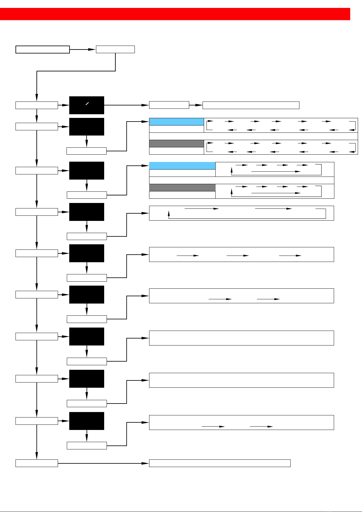
Power and link connector pinout.
Use any connector to power the
gauge and for less wiring use the
other connector with the supplied
link cable to power a second Muscle
Digital gauge ONLY!
Ignition harness / Fuse box
Ignition harness / Fuse box
SAAS Automotive PTY LTD
25 Metrolink Circuit West, Campbellfield,
Victoria 3061 Australia
ABN: 48166279670
ACN: 166279670
Phone: +61 3 9930 0100
Fax: +61 3 8339 2270
Email: tech@saasautomotive.com.au
Web: www.shopsaas.com
Warranty Terms & Conditions:
SAAS Automotive Pty Ltd warrants this product against defects in factory workmanship and materials for a
period of twelve (12) months from the date of original purchase. This warranty applies to the first retail
purchaser, is non-transferable and covers only where the product has been subjected to normal use or
service. Provision of this warranty shall not apply to any SAAS Automotive product that has been used for a
purpose for which it is not designed, or which has been altered in any way that would be detrimental to the
performance or life of the product, or misapplication, misuse, negligence or accident. Warranty claims to the
manufacturer must be transportation prepaid and accompanied with dated proof of purchase. On any part or
product found to be defective after examination by SAAS Automotive Pty Ltd, SAAS Automotive Pty Ltd will
only repair or replace the merchandise through the original selling dealer or on a direct basis. SAAS
Automotive Pty Ltd assumes no responsibility for diagnosis, removal and/or installation labour, loss of vehicle
use, loss of time, inconvenience or any other consequential expenses. The warranties herein are in lieu of any
other expressed or implied warranties, including any implied warranty of suitability, and any other obligation
on the part of SAAS Automotive Pty Ltd, or the selling dealer.
For further assistance email: tech@saasautomotive.com.au
Mounting U bracket with studs, nuts and washers
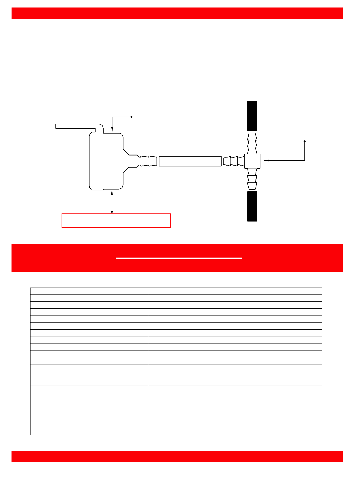
Boost sensor and 3 pin power harness
Boost hose and plastic tee
Please note: If you are having problems with the installation of this product, please do not
contact your retailer or SAAS until you have read ALL the troubleshooting notes below.
-gauge beeps and
flashes randomly
-warning function activated
-adjust warning settings accordingly
-gauge beeps but no
display
-refer to fitting instructions
-press button to change backlight colour
-sensor not plugged in correctly
-check connector on gauge and sensor
-boost line must come from intake
manifold before any factory sensors
-test sensor using a multimeter, a good
sensor should read: 1v @ 0 PSI or 1.6v
@ 10 PSI on the white signal wire
Boost sensor pinout:
White > Signal V+
Black > 12V-
Red > 12V+
Remote programming
button. Fit under dash
for easier programming.
(Installation optional)
Remote programming button
Fitting U bracket:
Remove nuts and add
stud spacers before fitting
U bracket if required.