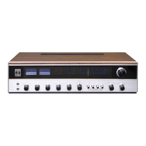
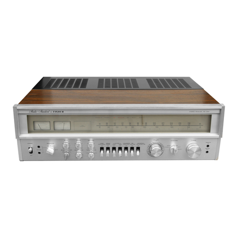
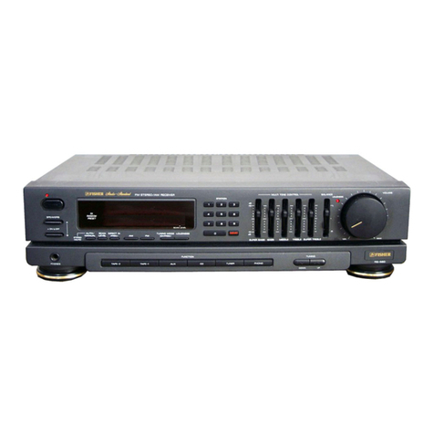
Fisher RS-2010 User manual

FISHER
OPERATING
INSTRUCTIONS
RS-2010
STEREO
RECEIVER
ESFISHER
...
THE
FIRST
NAME
IN
HIGH
FIDELITY
■
NOTE:
Locate
receiver's
serial
number
(shown
on
rear
panel
of
unit)
and
record
it
here
-

a
FISHER
RS-20TC)
SPECIFICATIONS
POWER
AMPLIFIER
SECTION
Continuous
RMS
sine
wave
power
per
channel
within
stated
bandwidth
at
no
more
than
stated
distortion
and
with
8
ohm
load
100
Watts
Power
Bandwidth
20
Hz
-
20
kHz
Total
Harmonic
Distortion
at
rated
power
0.03
%
I.M.
Distortion
0.03
%
Speaker
Damping
>40
PREAMPLIFIER
SECTION
Frequency
Response
Phono
(30
Hz
—
15
kHz)
±0.5
dB
Aux
(20
Hz-20
kHz)
±0.5
dB
Input
Sensitivity
and
Impedance
Phono
1,2
2
mV/50
k£2
Tape
Monitor
1,2
150
mV/100
k£2
Auxiliary
150
mV/100
k£2
Output
Voltage
and
Impedance
Tape
Out
(Rated
Output)
150
mV/5
k£2
Graphic
Equalizer
50
Hz
±10
dB
250
Hz
±10
dB
1
kHz
±10
dB
4.5
kHz
±10
dB
15
kHz
±10
dB
Filters
Subsonic
at
10
Hz
(18
dB/Oct.)
—10
dB
Loudness
Contour
(100
Hz/10
kHz)
+8
dB/+4
dB
Hum
and
Noise
(IHF
A
Weighted,
Inputs
Shorted)
Phono
1,2
76
dB
Aux/Tape
Monitor
1,2
90
dB
FM
TUNER
SECTION
Usable
Sensitivity
Mono
1.7
/XV/9.8
dBf
Stereo
4.3
MV/17.9
dBf
50
dB
Quieting
Sensitivity
Mono
2.5
jLlV/1
3.2
dBf
Stereo
34
fXV/35.9
dBf
Signal-to-Noise
Ratio
Mono/Stereo
75/70
dB
Capture
Ratio
0.8
dB
Alt.
Channel
Selectivity
(±400
kHz)
80
dB
Image
Response
Ratio
90
dB
Spurious
Response
Ratio
100
dB
IF
Response
Ratio
100
dB
AM
Suppression
Ratio
65
dB
Total
Harmonic
Distortion
at
65
dBf
Mono/Stereo
0.1/0.2%
T.H.D.
at
50
dB
Quieting
Sensitivity
Mono/Stereo
0.3/0.4
%
Stereo
Separation
(100
Hz/1
kHz/10
kHz)
40/50/40
dB
Sub-Carrier
Product
Rejection
(19/38
kHz)
65/70
dB
Audio
Frequency
Response
(20
Hz
-
15
kHz)
±0.5
dB
AM
TUNER
SECTION
Usable
Sensitivity
300/iV/m
Selectivity
(±10
kHz)
40
dB
Signal-to-Noise
Ratio
55
dB
Image
Response
Ratio
50
dB
IF
Response
Ratio
45
dB
GENERAL
120
V
AC
±10%
Power
Requirements
(50/60
Hz)
400
W/500
VA
AC
Outlets
2
Dimensions
WxDxH
20-5/16”x14-1/4”x6-11/16”
Weight
36
lbs.
*
Specifications
are
subject
to
change
without
notice.
2

INSTA
ANTENNA
CONNECTIONS
FM
OUTDOOR
ANTENNA
—
-111
-
SOOQ
FM
-T
INDOOR
0
ANTENNA
CH
CB
AM
OUTDOOR
ANTENNA
T
AM
INDOOR
ANTENNA
AM
0
0
0
0
CB
While
installation
is
relatively
simple,
certain
precautions
must
be
RANTY
DOES
NOT
COVER
DAMAGE
CAUSED
BY
MISHAN
INSUFFICIENT
VENTILATION.
We
therefore
urge
you
to
follow
CAUTION:
If
you
are
not
sure
whether
your
speakers
can
safely
h
do
not
turn
the
receiver’s
VOLUME
control
up
too
high.
FAI]
MANENTLY
DAMAGE
YOUR
SPEAKERS!
WARNING:
TO
PREVENT
FIRE
OR
SHOCK
HAZARD,
DO
NO
©
Swing
the
AM
ferrite
antenna
away
from
the
receiver
chas¬
sis
as
far
as
it
will
go
without
forcing
it.
Keep
all
speaker,
audio,
and
power
cables
away
from
this
antenna
and
never
use
it
as
a
handle.
r
-
RIGHT
SPEAKER
•
SPEAKER
£
YOUR
LISTEI
CONNECTION
OF
75
OHM
SHIELDED
CABLE
FROM
FM
ANTENNA.
RECORD
PLAYER
WITH
MAGNETIC
CARTRIDGE
STEREO
TAPE
RECORDER
1
STEREO
TAPE
RECORDER
2
Q
DE-EMPHASIS
SWITCF
This
switch
was
set
to
position
which
is
the
n
tion
when
listening
to
listening
to
DOLBY
external
decorder
(buil
FISHER
tape
decks),
se
to
the
25
f
JL
sec
position.

LUNG
THE
RECEIVER
RS-2010
EP*
bp
ibserved.
PLEASE
KEEP
IN
MIND
THAT
OUR
WAR¬
DING,
MISUSE,
EXCESSIVE
LINE
VOLTAGE,
OR
the
instructions
in
this
section
carefully
and
in
sequence.
ndle
the
maximum
audio-power
output
of
your
receiver,
URE
TO
OBSERVE
THIS
PRECAUTION
MAY
PER-

OPERATING
THE
RE
RS-2010
POWER
Switch
Press
in
the
POWER
button
to
switch
on
the
set.
Release
the
button
to
switch
off
the
set.
Do
not
worry
if
you
hear
a
slight
“thump”
during
switch-on
or
switch-off;
this
is
perfectly
normal
and
will
not
damage
any
part
of
your
system.
FUNCTION
Switch
Select
the
program
source
you
want
to
hear
(except
a
tape
recorder
or
deck,
covered
in
step
18):
•
AUX
—
To
play
other
sources
of
program
material,
such
as
a
sound
movie
projector,
tape
cartridge
player,
TV
set,
or
short
wave
tuner
through
the
receiver.
•
AM
—
To
listen
to
AM
broadcasts.
•
FM
-
To
listen
to
FM
broadcasts.
•
PHONO
1
—
To
listen
to
phonograph
records,
if
you
have
connected
a
record
player
to
the
PHONO
1
jacks.
•
PHONO
2
—
To
listen
to
phonograph
records,
if
you
have
connected
a
record
player
to
the
PHONO
2
jacks.
PANEL
LOGIC
display
The
panel
logic
display
is
a
visual
readout
panel
which
indicates
continuously
the
selected
receiver
functions,
the
operating
mode,
the
selected
speaker
system
or
systems,
and
the
position
selected
with
the
tape
monitor
switch.
This
section
describes
the
receiver’s
controls
in
the
order
in
which
yc
in
step-by-step
sequence.
You
will
master
complete
operation
of
the
ui
0
VOLUME
&
BALANCE
Controls
Initially,
adjust
the
VOLUME
control
for
a
low
listening
level.
After
selecting
a
program
source,
adjust
the
control
for
the
desired
volume
level.
Keep
the
BALANCE
control
at
its
mid-position
unless
the
volume
levels
in
the
left
and
right
channels
sound
unequal
at
your
listening
position.
In
such
a
case,
turn
the
control
either
towards
LEFT
or
RIGHT
to
restore
balance.
0
GRAPHIC
EQUALIZER
Controls
This
FISHER
Studio
Standard
RS-2010
receiver
is
equip¬
ped
with
a
newly
developed
GRAPHIC
EQUALIZER.
The
possibilities
of
altering
the
sound
to
your
liking
with
the
FISHER
GRAPHIC
EQUALIZER
are
endless.
It
places
at
your
fingertips
five
controls,
each
controlling
a
separate
section
of
the
audio
frequency
range.
The
advantage
of
the
FISHER
GRAPHIC
EQUALIZER
over
conventional
tone
controls
is
that
with
each
of
the
five
controls
of
the
GRAPHIC
EQUALIZER
it
is
possible
to
control
five
different
narrow,
distinct
sections
of
the
audio
band
pass
by
up
to
±10
dB.
This
corresponds
to
a
power
increase
of
10
times
or
a
power
decrease
to
1/10,
*
whereas
with
tone
controls
a
setting
for
a
bass
or
treble
^
boost
or
cut
will
also
affect
the
lower
or
upper
mid
fre¬
quencies.
?
©
©
©
©
VMMTS/WJ
WATTV8Q
^OWER
LEVEL
\P0VfER
LEVEL
|function|
|PHONOl|
|PHONQ2|
|TUNER|
|equal|
f
AUX
I-B~
X3
TAPE
]
■
I—~
UZHd
—
2
.
I
STEREol
-—-
SIWALSriKNOTH
CENTERO
'CHANNEL
—
[g
FISHER
—^
ILLLlllllllIIII
mill
11
I
III
M
II
I
mini
III
III
111
mm
iiiTnmi
IIIIIIIII
mu
i
mill
n^rrnr
Mu
100
102
Mm
mm
m
nlMimni
SPEAKERS
o:o
o:o
FILTERS
TAPEMON
FMMPX
SUBSOf
l(
5
2
0:0
OP
©
O
0
©
©0
©
®
l
©©
6
©
Fig.
2
c
c
<1
0

RECEIVER
h
which
you
would
normally
use
them.
Follow
the
instructions
bn
of
the
unit
in
a
very
short
time.
The
frequency
bands
controlled
by
the
five
slide
controls
with
stepped
detents
have
been
chosen
to
yield
the
maxi¬
mum
possible
control
action
within
the
audio
spectrum.
50
Hz
—
The
50
Hz
control
is
very
useful
in
enhancing
low
bass
notes
as
in
organ
music,
and
it
also
offers
the
possi¬
bility
to
make
corrections
when
a
deficiency
in
bass
exists,
caused
either
by
a
listening
room
with
poor
acoustic
properties
like
bass
absorbing
curtains,
carpets
and
furni¬
ture,
or
by
a
component
part
of
your
system
like
a
speaker,
cartridge
or
record
with
a
poor
bass
response.
250
Hz
—
The
250
Hz
control
will
allow
you
to
vary
the
upper
bass
frequencies.
1
kHz
—
The
1
kHz
control
is
the
presence
control
and
can
be
used
very
effectively
to
emphasize,
bring
out
front,
or
de-emphasize
vocalists.
4.5
kHz
—
The
4.5
kHz
control
will
add
brilliance
and
clarity
to
brass
instruments
and
violins.
15
kHz
—
The
15
kHz
control
can
be
used
to
make
up
for
missing
high
frequencies
absorbed
by
the
environment
and
to
add
a
natural
crispness
to
music.
0
EQUAL
Switch
In
the
OFF
position,
the
GRAPHIC
EQUALIZER
controls
are
disconnected
and
a
perfectly
flat
frequency
response
is
obtained.
Set
it
to
the
ON
position,
to
bring
GRAPHIC
EQUALIZER
controls
into
operation.
0
TUNING
Knob
If
you
have
selected
FM
or
AM
in
step
2,
tune
in
the
desired
station.
0
FM
STEREO
Indicator
With
the
FUNCTION
switch
in
the
FM
position,
the
indi¬
cator
will
light
when
an
FM
stereo
broadcast
is
received.
If
the
indicator
does
not
light
during
the
reception
of
an
FM
stereo
program,
this
indicates
insufficient
signal
strength.
Flashing
of
the
indicator
is
due
to
spurious
interference.
Neither
phenomenon
indicates
any
problem
with
the
unit.
0
SIGNAL-STRENGTH
Meter
Maximum
deflection
of
the
meter
pointer
indicates
that
an
AM
or
FM
station
is
tuned
in
with
optimum
accuracy.
0
CENTER-OF-CHANNEL
Meter
Turn
the
tuning
knob
and
observe
first
the
pointer
of
the
signal-strength
meter
for
maximum
deflection
to
the
right.
Then
turn
the
tuning
knob
very
slowly
until
the
pointer
of
the
CENTER-OF-CHANNEL
meter
is
in
the
center
of
the
scale
within
the
gap.
0
SPEAKERS
Switch
Set
the
SPEAKERS
switch
to
A
or
B
or
C
or
A+B
positions,
depending
on
the
rear
terminals
to
which
your
speaker
system
is
connected.
Use
the
PHONES
position
when
you
intentionally
want
to
turn
off
your
speakers
(to
listen
privately
through
headphones,
or
to
silence
the
music
system
momentarily,
etc.).
0
POWER
Meters
The
power
meters
indicate
the
approximate
music
program
power
output
levels
delivered
to
the
speaker
systems.
The
power
meters
may
also
be
used
for
continuous
system
monitoring
where
they
provide
an
instantaneous
indication
of
left
and
right
channel
power
distribution
and
channel
balance.
0
LOUDNESS
CONTOUR
Switch
Set
this
button
to
the
ON
or
OFF
position
as
desired.
Pressing
it
to
the
ON
position
will
restore
tonal
balance
and
brilliance
at
normal
and
lower
volume
levels.
0
MONO
MODE
Switch
The
only
times
you
will
have
to
press
the
MONO
MODE
button
are:
•
When
listening
to
the
occasional
FM
stereo
broadcast
that
sounds
noisy
and
causes
erratic
STEREO
Light
blinking
with
the
MONO
MODE
button
out.
•
When
playing
a
mono
auxiliary
source
or
mono
record
through
the
receiver.
0
FM
MUTE
Switch
Keep
this
button
in
the
ON
position
to
silence
between-
station
noise
and
weak,
noisy
FM
stations.
Push
this
button
in,
to
the
OFF
postion
only
when
you
wish
to
listen
to
such
stations.
0
FM
MPX
FILTER
Switch
Push
this
button
in,
to
the
ON
position
to
reduce
noise
interference
during
FM
stereo
program
reception.
0
SUBSONIC
FILTER
Switch
Push
this
button
in,
to
the
ON
position
only
when
playing
old
phonograph
records
which
contain
rumble,
or
when
using
a
record
player
which
produces
low-frequency
noise.
At
all
other
times
this
button
should
be
set
to
the
OFF
position.
0
TAPE
MONITOR
Switches
Keep
these
buttons
in
the
SOURCE
position
so
that
you
do
not
accidentally
silence
any
program
source
chosen
with
the
FUNCTION
switch.
Push
the
TAPE
MONITOR
1
button
in,
to
the
TAPE
position
only
when
you
wish
to
play
back
or
monitor
tapes
from
a
tape
recorder
or
deck
connected
to
the
receiver’s
TAPE-1
IN
jacks.
Push
the
TAPE
MONITOR
2
button
in,
to
the
TAPE
position
only
when
you
wish
to
play
back
or
monitor
tapes
from
a
tape
recorder
or
deck
connected
to
the
receiver’s
TAPE-2
IN
jacks.
Push
the
TAPE
MONITOR
1
button
in,
to
the
TAPE
position
and
release
the
TAPE
MONITOR
2
button
out,
to
the
SOURCE
position
when
you
wish
to
duplicate
from
a
tape
recorder
or
deck
(in
the
playback
mode)
connected
to
the
receiver’s
TAPE-1
jacks
to
a
tape
recorder
or
deck
(in
the
recording
mode)
connected
to
the
receiver’s
TAPE-2
jacks.
0
PHONES
Jack
For
private
listening
insert
STEREO
HEADPHONES.
(See
page
6
for
details.)

TROUBLE-SHOOTING
GUIDE
If
you
have
followed
the
instructions
in
the
INSTALLING
and
OPERATING
sections,
and
have
trouble
operating
your
system,
locate
the
SYMPTOM
in
the
left
column
below.
Check
the
corresponding
POSSIBLE
CAUSE
and
CORRECTIVE
ACTION
columns
to
locate
and
remedy
the
problem.
SYMPTOM
POSSIBLE
CAUSE
CORRECTIVE
ACTION
POWER
switched
ON
but-
no
sound
and
no
light
on
Dial
Scale.
Faulty
AC
power
plug
con¬
nection
to
wall
outlet.
Examine
plug.
Old
wall-outlets
sometimes
cause
power
loss.
Plug
must
fit
snugly
in
outlet.
Receiver’s
POWER
FUSE
blown.
Replace
receiver’s
POWER
FUSE
according
to
directions
in
the
MAINTENANCE
section.
Dial
Scale
lit
but
no
sound
(or
very
weak
sound)
from
FM,
AM,
and
PHONO.
TAPE
MONITOR
button
pressed
in.
Relese
TAPE
MONITOR
button.
NOTE:
Turn
VOLUME
control
down
to
avoid
damage
to
your
loudspeakers.
SPEAKERS
switch
set
to
PHONES.
Reset
SPEAKERS
switch
to
A
or
B
or
C
or
A+B.
(See
No.
11
on
page
4)
Sound
from
one
speaker
only.
BALANCE
control
turned
all
the
way
to
one
side.
Reset
BALANCE
control
to
center
position.
Speaker
wired
incorrectly.
Check
connections
of
speaker
cables
in
the
rear
of
the
receiver
and
at
the
terminals
on
the
back
of
each
speaker.
Check
to
see
that
no
strands
of
wire
connected
to
terminals
on
the
receiver
or
speaker
touch
the
chassis
or
any
other
terminal.
Be
sure
wires
are
firmly
secured
to
each
terminal.
PHONO
has
loud
hum
with
normal,
little,
or
no
audio.
FM
and
AM
are
OK.
Faulty
connection
between
record
player
and
receiver.
Check
and
crimp
outside
(shell)
of
phono
cable
plugs.
Loud
howling
sound
when
recording
with
microphone
on
tape
recorder.
TAPE
MONITOR
button
pressed
in.
Release
TAPE
MONITOR
button.
Press
in
TAPE
MONITOR
button
only
during
playback
from
the
recorder,
or
while
monitoring
from
3-head
tape
deck.
Poor
FM
reception.
No
antenna
connected.
Connect
an
FM
antenna
to
the
FM
ANT.
termi¬
nals
at
the
rear
of
the
receiver.
Refer
to
the
INSTALLING
illustration
and
the
ANTENNAS
section.
Shorted
or
faulty
connec¬
tions)
between
FM
antenna
and
receiver.
Check
connections
of
FM
antenna
leads
at
the
rear
of
the
receiver.
Antenna
not
oriented
for
best
reception.
Change
position
of
(or
rotate)
antenna.
Refer
to
the
ANTENNAS
section.
No
FM
STEREO
stations
received.
MONO
MODE
button
pressed
in.
Release
MONO
MODE
button.
5

HEADPHONES
AND
REMOTE
SPEAKERS
WARNING:
If
you
are
not
sure
whether
each
of
your
remote
speakers
can
safely
handle
the
maximum
audio-power
output
per
channel
of
your
receiver,
do
not
turn
your
receiver’s
VOLUME
control
up
too
high.
FAILURE
TO
OBSERVE
THIS
PRECAUTION
MAY
PERMANENTLY
DAMAGE
YOUR
SPEAKERS!
STEREO
HEADPHONES
For
private
listening
to
all
program
sources,
you
may
plug
a
pair
of
stereo
headphones
into
the
PHONES
jack
on
the
control
panel.
When
using
the
headphones
for
the
first
time,
turn
the
VOLUME
control
to
MIN
and
set
the
SPEAKERS
switch
to
PHONES
before
plugging
in
the
phones.
Readjust
the
VOLUME
control
for
comfortable
headphone
listening
level
and
use
this
setting
for
future
reference.
CAUTION:
Do
not
leave
the
headphones
plugged
in
when
playing
the
speakers
at
high
volume
levels.
The
large
amounts
of
audio
power
required
by
the
speakers
at
these
levels
can
overload
and
damage
the
headphones.
STEREO
REMOTE
SPEAKERS
The
receiver’s
B
or
C
speaker
terminals
on
the
rear
of
the
unit
provide
convenient
means
for
connecting
a
pair
of
remote
extension
speakers.
This
arrangement
will
enable
you
to
en¬
joy
stereo
sound
in
other
rooms
of
your
home
whenever
you
set
the
SPEAKERS
switch
to
B,
C
or
A+B.
CAUTION:
Before
connecting
your
B
or
C
speakers,
check
their
rated
impedance
and
the
impedance
of
your
A
speakers
as
well.
If
each
speaker
is
rated
at
8
or
16
ohms,
you
may
safely
connect
your
B
or
C
speakers
as
described
in
the
following
instructions.
In
the
rare
event
that
the
A
or
B
speaker
is
rated
at
4
ohms,
have
a
technician
add
a
2-ohm,
10-watt
resistor
in
series
with
that
speaker.
Failure
to
observe
this
precaution
may
cause
overload
and
distortion
when
you
play
the
A
plus
B
speakers
simultaneously
at
high
volume
levels.
(Only
in
A+B
position
of
the
SPEAKERS
switch.)
1)
Turn
off
the
receiver
and
disconnect
its
power
cord
from
the
electrical
outlet.
2)
Place
your
B
or
C
speakers
5
to
10
feet
apart,
facing
your
listening
position,
and
as
close
as
possible
to
ear
level.
Connect
both
speakers
exactly
as
shown
in
the
illustration
(each
speaker’s
COM,
GND,
or
black
terminal
to
its
corre¬
sponding
COM
terminal
on
the
receiver).
Use
either
the
cables
supplied
with
the
speakers
or,
for
distances
up
to
30
feet,
No.
18
lamp
cord
or
flat
TV
twin-lead.
For
longer
distances,
use
heavy-duty
cable
(at
least
No.
16).
Make
sure
that
the
bare
wires
at
the
ends
of
the
cables
do
not
touch
each
other,
adjacent
terminals,
or
the
receiver’s
chassis.
Reconnect
the
power
cord
and
set
the
SPEAKERS
switch,
as
desired.
Adjust
all
other
receiver
controls
in
the
usual
manner.
SPEAKERS
(8
S
I)
RIGHT
COM
COM
LEFT
6

ANTENNAS
FM
ANTENNAS
(Refer
also
to
INSTALLING
section)
The
following
paragraphs
provide
instructions
for
replacing
the
FM-dipole
antenna
with
other
indoor
or
outloor
anten¬
nas
to
suit
local
receiving
conditions:
REDUCING
MULTIPATH
INTERFERENCE
In
some
strong-signal
localities,
pronounced
signal
reflections
from
surrounding
buildings,
towers,
or
hills
may
cause
multi-
path
interference.
(This
phenomenon
is
similar
to
“ghosts”
in
TV
pictures
and
can
cause
distortion,
“fuzziness”,
and
reduced
left-right
separation
in
FM-stereo
broadcasts.)
In
such
cases,
it
may
be
necessary
to
replace
the
dipole
an¬
tenna
with
an
indoor
“rabbit-ears”
or
telescoping-dipole
an¬
tenna
that
can
be
rotated
for
best
reception
of
the
desired
signal
and
maximum
rejection
of
the
unwanted
reflections.
(This
type
of
antenna
is
available
at
most
electronic-parts
dealers.)
Disconnect
the
dipole
antenna
from
the
FM
ANT.
terminals
and
connect
the
rabbit-ears
antenna
in
its
place,
making
sure
that
the
antenna
lugs
or
wires
do
not
touch
each
other,
ad¬
jacent
terminals,
or
the
receiver
chassis.
Tune
in
several
FM
stations
and
rotate
the
antenna
for
best
reception
of
each.
IMPROVING
FRINGE-AREA
RECEPTION
AND
REDUCING
ELECTRICAL
INTERFERENCE
In
weak-signal
“fringe”
areas
an
outdoor
antenna
may
be
nec¬
essary,
especially
for
effective,
noise-free
FM-stereo
recep¬
tion.
If
you
already
have
an
outdoor
VHF
television
antenna,
and
know
that
FM
signals
in
your
area
come
from
the
same
general
direction
as
the
TV
signals,
the
antenna
may
prove
suitable
for
FM
reception
as
well.
To
test
it,
disconnect
the
dipole
antenna
from
the
FM
ANT.
terminals
and
connect
the
TV
antenna
in
its
place,
making
sure
that
the
antenna
lugs
or
wires
do
not
touch
each
other,
adjacent
terminals,
or
the
receiver
chassis.
If
the
results
are
satisfactory,
obtain
a
two-set
antenna
coupler
so
that
you
can
operate
both
the
TV
set
and
the
receiver
from
the
antenna
simultaneously.
If
reception
is
still
unsatisfactory,
you
may
have
to
connect
an
outdoor
antenna
designed
specifically
for
FM.
In
medium-
fringe
areas
(up
to
40
miles
from
stations),
where
most
signals
come
from
the
same
general
direction,
a
folded
dipole
with
reflector
should
provide
good
results.
If
signals
come
from
several
different
directions,
an
omnidirectional
antenna
such
as
a
cross-dipole,
“turnstile”,
or
“S”
will
eliminate
the
necessity
for
an
antenna
rotator.
For
deep
fringe
areas
50
miles
or
more
from
stations,
a
high-gain
“Yagi”
array
or
Log-
Periodic
antenna
is
recommended.
These
antennas
are
quite
directional
however,
and
if
station
signals
come
from
several
directions,
you
will
probably
require
a
remote-control
antenna
rotator.
If
you
live
near
a
busy
thoroughfare
or
industrial
area,
and
the
outdoor
antenna
is
connected
to
the
set
with
conven¬
tional
300-ohm
twin-lead,
interference
from
automotive
ignition
systems
or
electrical
machinery
may
radiate
into
the
long
lead-in,
causing
objectionable
noises
throughout
the
FM
band.
In
such
cases,
replace
the
conventional
lead-in
with
shielded
7
5-ohm
cable
(available
at
your
local
Hi-Fi
store).
Connect
the
lead-in’s
two
signal
conductors
to
the
receiver’s
75-ohm
FM
ANT.
terminals
in
the
manner,
shown
in
the
INSTALLING
section.
AM
ANTENNAS
If
AM
reception
is
marred
because
you
live
in
a
steel-frame
building,
or
if
you
want
to
supplement
the
built-in
AM
an¬
tenna
for
improved
reception
of
weaker
stations,
connect
10
to
20
feet
of
insulated,
flexible,
single-conductor
wire
to
the
EXT
AM
ANT.
terminal.
Keep
this
wire
away
from
all
speaker,
audio,
and
power
cables.
Run
the
wire
in
a
straight
line
along
a
non-metallic
baseboard
or
under
a
rug.
In
some
cases,
reception
may
be
further
improved
by
draping
the
wire
out
a
window
or
by
connecting
it
to
an
outdoor
whip
or
rod
antenna.
at
7

ADDITIONAL
COMPONENTS
CAUTION:
Do
not
connect
any
additional
components
without
first
turning
off
the
receiver.
STEREO
RECORD
PLAYER
OR
CHANGER
Connect
a
stereo
record
player
or
changer
having
a
magnetic
cartridge
exactly
as
shown
in
the
INSTALLING
section.
If
the
record
player
or
changer
has
a
ground
wire
with
a
spade
or
hook
lug
at
its
free
end,
connect
this
lug
to
the
slotted-head
ground
screw
near
the
receiver’s
PHONO
1
jacks.
This
is
im¬
portant
for
hum-free
sound
from
your
records.
Usually,
the
record
player’s
OPERATING
INSTRUCTIONS
Manual
will
tell
you
how
to
distinguish
between
the
left-
and
right-channel
audio
cables.
If
not,
temporarily
connect
them
at
random
and
connect
the
record
player’s
power
cord
to
the
switched
AC
outlet
at
the
rear
of
your
receiver.
Then
check
for
correct
left-right
stereo
placement
as
follows:
Turn
on
the
receiver,
make
sure
that
the
MONO
MODE
button
is
out,
and
set
the
FUNCTION
switch
to
PHONO
1
or
2,
depending
on
the
rear
terminals
to
which
your
record
player
or
changer
is
con¬
nected.
Play
a
stereo
symphonic
or
orchestral
recording
and
adjust
the
VOLUME
control
for
a
comfortable
listening
level.
Listen
to
the
placement
of
the
violins;
if
they
seem
to
come
from
-
or
near
—
the
left
speaker,
as
viewed
from
your
listen¬
ing
position,
the
cables
are
properly
connected.
If
not,
turn
off
the
receiver
and
reverse
the
connections
of
the
audio
cables.
AUXILIARY
PROGRAM
SOURCE
You
may
increase
the
versatility
of
the
receiver
by
playing
an
additional
program
source
through
the
AUX
jacks.
If
the
source
plays
through
its
own
low-fidelity
speaker(s)
and
am¬
plifiers),
playing
it
through
the
receiver
instead
will
improve
its
sound
quality.
The
auxiliary
source
may
be
a
short-wave
or
multiband
radio
tuner,
a
TV
set
or
sound-movie
projector,
or
any
other
similar
device
so
long
as
it
has
at
least
one
audio
output
jack.
The
jack
is
generally
marked
LINE
OUTPUT,
TO
AMPLIFIER,
TO
TAPE
RECORDER,
or
the
like.
If
the
device
does
not
have
the
required
jack,
a
qualified
service
technician
can
install
one
and,
if
necessary,
add
provisions
for
switching
off
its
built-in
speakers.
If
the
device
is
an
AC/DC
or
“transformer¬
less”
type,
make
sure
that
the
technician
eliminates
shock
hazard
and
hum
caused
by
a
“hot”
(electrically
not
isolated)
chassis.
If
you
are
in
doubt
about
the
safety
characteristics
of
the
device,
do
not
connect
it
to
the
receiver.
1)
T
urn
off
the
receiver.
Depending
on
whether
the
auxiliary
device
is
mono
or
stereo,
connect
it
to
the
receiver
as
follows:
•
If
the
device
is
mono,
connect
its
single
output
jack
to
the
receiver’s
LEFT
and
RIGHT
AUX
jacks.
(Use
a
shielded
“Y”-connector
audio
cable
with
the
appropriate
plug
on
each
of
its
three
legs.)
•
If
the
device
is
stereo
connect
its
LEFT,
L,
A,
or
1
output
jack
to
the
receiver’s
LEFT
AUX
jack,
and
its
RIGHT,
R,
B,
or
2
output
jack
to
the
receiver’s
RIGHT
AUX
jack.
(Use
two
shielded
audio
cables
with
the
appropriate
plugs
at
their
ends.)
2)
Connect
the
device’s
power
cord
to
a
convenient
electrical
outlet.
Keep
the
power
cord
away
from
all
shielded
cables.
3)
Turn
on
the
receiver
and
the
auxiliary
device,
turn
the
FUNCTION
switch
to
AUX
position,
and
set
the
receiver’s
VOLUME
control
to
a
comfortable
level.
4)
Turn
the
FUNCTION
switch
either
to
FM
or
AUX
posi¬
tions,
and
compare
the
relative
volume
levels
of
the
two
program
sources.
They
should
be
approximately
equal
without
your
having
to
readjust
the
VOLUME
control
drastically
each
time
you
switch.
If
the
auxiliary
device
has
any
controls
that
affect
its
volume
(as
heard
through
the
receiver),
adjust
them
to
equalize
volume
levels.
EXTERNAL
TAPE
RECORDER
OR
DECK
Your
receiver
has
provisions
for
connecting
a
tape
recorder
or
tape
deck
so
that
you
may
record
any
program
source
to
which
you
are
listening.
If
the
receiver’s
AUX
jacks
are
presently
unused,
you
may
also
connect
the
recorder
to
play
back
the
recording
(or
any
previously
recorded
tape)
through
the
receiver
at
your
convenience.
In
any
event,
the
recorder
may
be
an
open-reel,
tape-cassette,
or
tape-cartridge
type.
CONNECTING
ONE
RECORDER
The
following
instructions
(and
illustration
in
the
INSTALL¬
ING
section)
will
permit
you
to
record
any
program
source
to
which
you
are
listening,
and
then
to
play
back
the
recording
(or
any
previously
recorded
tape)
through
the
receiver
at
your
convenience.
(If
the
recorder
is
specially
equipped
as
de¬
scribed
in
step
5,
the
receiver
will
also
permit
you
to
“monitor”
the
quality
of
the
taped
signal
while
recording.)
1)
Turn
off
the
receiver.
The
stereo
recorder
should
have
a
pair
of
high-level
recording
input
jacks
marked
HIGH
LEVEL,
LINE
INPUT,
or
the
like.
Using
two
shielded
audio
cables
with
the
appropriate
plugs
at
their
ends,
connect
the
LEFT,
L,
A,
or
1
jack
to
the
receiver’s
LEFT
TAPE-1
OUT
jack,
and
the
RIGHT,
R,
B,
or
2
jack
to
the
receiver’s
RIGHT
TAPE-1
OUT
jack.
2)
The
recorder
should
also
have
a
pair
of
playback
output
jacks
marked
PLAYBACK
OUTPUT,
CATHODE
FOL¬
LOWER,
LINE
OUTPUT,
MONITOR,
EXTERNAL
AM¬
PLIFIER,
or
the
like.
Using
two
more
shielded
audio
cables
with
the
appropriate
plugs
at
their
ends,
connect
the
LEFT,
L,
A,
or
1
jack
to
the
receiver’s
LEFT
TAPE-1
IN
jack,
and
the
RIGHT,
R,
B,
or
2
jack
to
the
receiver’s
RIGHT
TAPE-1
IN
jack.
3)
Connect
the
receiver’s
power
cord
to
the
unswitched
AC
outlet
at
the
rear
of
your
receiver.
Keep
the
power
cord
as
far
as
possible
from
all
shielded
audio
cables.
8

4)
To
record,
turn
on
the
receiver
and
the
recorder.
Choose
the
desired
program
source
with
the
receiver’s
FUNCTION
switch;
the
source
to
which
you
are
listening
is
the
source
that
will
be
recorded.
Then
operate
the
recorder
in
the
re¬
cording
mode
as
specified
in
its
OPERATING
INSTRUC¬
TIONS
Manual.
The
FUNCTION
switch
is
the
only
re¬
ceiver
control
that
has
any
effect
on
the
recording
(except,
of
course,
the
Tuning
control
if
you
are
recording
a
radio
broadcast);
you
may
therefore
adjust
all
other
controls
in
the
usual
manner
as
described
in
the
OPERATING
section.
5)
If
your
recorder
has
true
tape-monitor
facilities
(different
circuits
and
heads
for
recording
than
for
playbak),
you
may
monitor
the
tape
—
while
recording
-
to
compare
its
sound
quality
with
that
of
the
original
program
from
which
it
is
being
recorded.
This
feature
permits
you
to
detect
and
correct
any
possible
recording
errors
almost
immediately.
To
monitor,
alternate
the
receiver’s
TAPE
MONITOR
1
button
between
SOURCE
(to
hear
the
origi¬
nal
program
as
usual)
and
TAPE
(to
hear
the
same
material,
a
fraction
of
a
second
later,
as
it
sounds
on
tape).
You
may
repeat
this
as
often
as
you
like,
or
even
keep
the
button
in
TAPE
without
affecting
or
interrupting
the
recording
process
in
any
way.
When
you
have
finished
recording,
remember
to
depress
the
TAPE
MONITOR
1
button
to
SOURCE
so
that
you
do
not
accidentally
silence
any
other
program
source
choosen
with
the
FUNCTION
switch.
6)
To
play
back
tapes,
simply
depress
the
receiver’s
TAPE
MONITOR
1
button
to
TAPE
and
operate
the
recorder
in
the
playback
mode
as
specified
in
its
OPERATING
INSTRUCTIONS
Manual.
Adjust
all
other
receiver
controls
in
the
usual
manner
as
described
in
the
OPERATING
section.
When
you
have
finished
playing
tapes,
remember
to
depress
the
TAPE
MONITOR
1
button
to
SOURCE
so
that
you
do
not
accidentally
silence
any
other
program
source
chosen
with
the
FUNCTION
swicth.
CONNECTING
A
SECOND
RECORDER
This
permits
you
to
tape
any
phonograph
record
or
radio
broadcast
on
the
first
or
second
recorder,
or
on
both
re¬
corders
simultaneously.
It
will
also
permit
you
to
play
back
a
previously
recorded
tape
on
the
first
recorder
while
making
a
duplicate
copy
(or
“dubbing”)
on
the
second
recorder.
Con¬
nect
the
second
recorder’s
high-level
recording
inputs
to
the
receiver’s
TAPE-2
OUT
jacks,
and
the
second
recorder’s
play¬
back
outputs
to
the
receiver’s
TAPE-2
IN
jacks.
To
make
a
tape
copy
of
a
record
or
broadcast
on
the
first
and/or
second
recorder,
choose
the
desired
program
source
with
the
re¬
ceiver’s
FUNCTION
switch,
and
operate
either
or
both
re¬
corders
in
the
recording
mode.
To
duplicate
or
“dub”,
from
the
first
recorder
to
the
second
recorder,
depress
the
TAPE
MONITOR
1
button
to
TAPE
and
the
TAPE
MONITOR
2
button
to
SOURCE.
Then
operate
the
first
recorder
in
the
playback
mode
and
the
second
recorder
in
the
recording
mode.
If
your
recorder
has
true
tape-monitor
facilities
(dif¬
ferent
circuits
and
heads
for
recording
than
for
playback),
you
may
monitor
the
tape
-
while
recording
—
by
depressing
the
TAPE
MONITOR
2
button
to
TAPE.
To
play
back
tapes,
simply
depress
the
receiver’s
TAPE
MONI¬
TOR
2
button
to
TAPE
and
operate
the
recorder
in
the
play¬
back
mode
as
specified
in
its
OPERATING
INSTRUCTIONS
Manual.
Adjust
all
other
receiver
controls
in
the
usual
manner
as
described
in
the
OPERATING
section.
When
you
have
finished
playing
tapes,
remember
to
depress
the
TAPE
MONI¬
TOR
2
button
to
SOURCE
so
that
you
do
not
accidentally
silence
any
other
program
source
chosen
with
the
FUNCTION
switch.
9

MAINTENANCE
CAUTION:
Turn
off
the
receiver
and
disconnect
its
power
cord
from
the
electrical
outlet
whenever
instructed
to
do
so
in
the
following
procedures.
Do
not
attempt
any
maintenance
not
listed
in
this
section.
For
further
service,
consult
your
Fisher
dealer,
local
Fisher
Service
Center,
or
Service
Department,
Fisher
Corporation.
(If
returning
your
unit
for
service,
please
do
not
include
this
OPERATING
INSTRUCTIONS
Manual,
the
Service
Manual,
or
the
dipole
antenna.)
CLEANING
THE
RECEIVER'S
EXTERIOR
The
receiver’s
control
panel
and
wood-grain
vinyl-clad
cover
will
retain
their
color
and
brilliance
permanently.
However,
it
is
possible
that,
over
a
period
of
time,
a
film
from
atmo¬
spheric
contamination
may
dull
the
surfaces.
Simply
use
a
soft,
freshly
laundered
cloth
moistened
with
plain
lukewarm
water
to
wipe
the
surfaces
clean
and
your
receiver
will
look
like
new
again.
Do
not
use
any
household
or
industrial
cleaning
agents,
or
any
cloth
that
has
been
used
to
apply
such
agents.
2)
Turn
the
fuseholder
cap
counterclockwise
until
it
dis¬
engages
from
the
receptacle,
and
remove
the
fuse
from
the
cap.
3)
Obtain
a
replacement
fuse
whose
electrical
rating
is
iden¬
tical
to
that
marked
next
to
the
fuse
receptacle
or
stamped
on
the
original
fuse
itself.
4)
Insert
the
replacement
fuse
in
the
fuse
cap.
Push
the
cap
into
its
receptacle
and
turn
it
clockwise
until
it
is
firmly
in
place.
Connect
the
power
cord
to
the
electrical
outlet
and
turn
the
receiver
on.
REPLACING
FUSES
CAUTION:
If
the
TROUBLE-SHOOTING
GUIDE
in
this
OPERATING
INSTRUCTIONS
Manual
indicates
that
a
malfunction
may
be
caused
by
a
blown
fuse
in
the
rear
of
the
set,
proceed
as
follows:
1)
Turn
off
the
receiver
and
disconnect
its
power
cord
from
the
electrical
outlet.
If
the
malfunction
persists
or
recurs
within
a
short
time,
do
not
attempt
to
replace
the
fuse
again.
Consult
your
dealer,
or
local
Fisher
Service
Center,
or
Fisher
Corporation.
t
f*
•K
10

OPERATING
GUIDE
Z
NCTIO
Switch
FM
FM
AM
HONO
1
or
2
HONO
1
or
2
e
>3.2
c
.to
<
8
AUX
D
PL
Oh
CL
CL,
oq
TO
73
73
73
73
73
73
z
2
2
<D
CD
2
CD
CD
CD
Z-H
j-H
t3
0
CD
CD
a>
CD
s
D
J
o
c
c
c
C
c
c
c
<
u
CQ
CD
CD
CD
CD
D
CD
<D
u
u
U
U
u
u
U
tL)
73
73
73
73
73
73
CD
<D
CD
CD
D
CD
<D
S
o
j-h
Vh
Vh
S-H
Vi
Vh
Vh
C/3
O
C/3
CD
C/3
CD
’c/3
CD
’c/3
CD
C/3
CD
’c/3
CD
V-H
P
u
Q
Q
Q
Q
Q
Q
Q
C/3
C/3
00
C/3
c«
C/3
C/i
>
C
<
<
<
<
<
0
*
t/)
wg
«
w
CL)
CL)
CO
CL)
CL)
0
0
u
QJ
U
(N
U
Oh
E
0
04
04
04
0
^
04
V-t
cc;
<
Z
•
s
D
D
D
D
0
O
D
H
0
J:
0
O
O
O
0
*—
1
O
C/3
<D
X
O
S
1/3
CO
CO
CO
CO
CO
co
><
g
c*
S
-+->
Cl
CL
CL
Cl
CL
CL
CL
£
s
S
5
£
5
OQ
M
£
cl
Ch
CL
Cl
CL
CL
CL
CO
O
0
O
O
O
O
O
73
cs
cd
£
D
Cl
co
CO
(73
o
g
a!
Cl
CL
CL
Cl
CL
CL
CL
+3
W
3
Z
0
2
Cl
CL
CL
Cl
CL
Cl
Ch
c
o
O
O
O
O
O
O
0
n
h
vh
V-t
Vh
Vh
V-,
Vh
w
5
Z
^
0
O
O
O
O
0
O
5
0
m
Z
Z
z
z
z
Z
z
3
U
O
O
0
0
0
O
0
CL
c
0
w
-c
OFF
o
Vh
CL
2
Q
S
S
S
&o
ON
OFF
ON
ON
OFF
OFF
CO
fn
S
H
§
z
z
z
Z
Z
Z
z
^
2
^
0
0
0
0
O
O
0
s
&
d
x
D
S
z
z
z
z
z
z
z
O
£
0
0
0
0
0
0
0
W
^
04
CO
/
■
—\
/-“N
Z“\
7—S
73
73
73
73
73
73
73
73
73
73
73
73
73
73
u
W
’o
2
0
CD
CD
CD
CD
<D
CD
(D
CD
CD
CD
2
2
a
n
2
T
M
'M
S
-)
g
5
*s
L*
«
0
Q
^
*55
C
^
CD
Q
£
-S
3
a
%
cd
Cl
S
•§
C
^
cd
CO
S
‘S
a
^
CD
Q
5
•§
C
«
CD
Q
«
*53
a
D
Q
s
S
u
U
CO
U
c/3
U
GO
O
CO
CJ
C/3
U
GO
CJ
GO
K
D
_
005
W
^
p
0
P
O
P
O
P
0
P
O
p
0
P
O
CO
W
J=!
u
CJ
u
U
u
u
U
s«
£
PQ
°
+
£
00
0
+
^
00
0
+
PQ
°
+
^
00
0
+
^
PQ
°
+
00
<
00
<
00
<
CQ
<
00
<
00
<
00
<
Vh
Vh
fc;
Vh
}_
5
—i
1_
Vh
^
Vh
v_
CL)
CO
0
0
O
O
0
0
O
O
0
0
O
O
O
O
Cl
co
<
<
<
<
<
<
<
cd
(N
tt
<*>
C
CS
5
—1
’—3
CO
™
,
Sh
C/3
.2
C
4
g
<
H
Z
<
c
c
p
D
^
2
g-
O
O
g«
0
0
Vh
O
rH
Z
w
l
"
H
%
H
g
ts
0
c
s
£
£
Dh
H
Cl
s
CL
SJ
<
«
s
<C
X
^
Oh
X
r-H
Ol
<
CD
W)
73
+H
cd
7
—s
U
C/3
73
(73
73
V-i
>3
•a
0
V-i
0
O
0
°
cd
Vh
£
0
0
O
CD
H
§
^
s
0
CL
CL
OC
04
h
g
06
O
O
0
0
O
X)
0
00
b
2
g
a
0
0)
i-H
CD
0
0
2
CD
S
^
<D
Lh
CD
Vh
CD
Vh
O
Oh
CO
S
oS
<
S
X
+H
Q.
co
0
Si
11
Please
read
the
OPERATING
INSTRUCTIONS
Manual
for
more
detailed
information.

FISHER
THE
FIRST
NAME
IN
HIGH
FIDELITY
FISHER
CORPORATION,
21314
LASSEN
STREET
•
CHATSWORTH
•
CALIFORNIA
91311
Copyright
1978,
Fisher
Corporation.
All
Rights
Reserved.
Printed
in
Japan
1316-4119-69502
RS-2010,
Issue
Number
1.
Table of contents
Other Fisher Stereo Receiver manuals

Fisher
Fisher 220T User manual

Fisher
Fisher 800-C Installation guide
Fisher
Fisher TAC-M82 User manual

Fisher
Fisher 4020 User manual

Fisher
Fisher 500-TX User manual

Fisher
Fisher Studio-Standart 504 User manual

Fisher
Fisher 500-T Installation guide

Fisher
Fisher 400 User manual

Fisher
Fisher Studio-Standart 504 User manual
Fisher
Fisher CR-5125 User manual