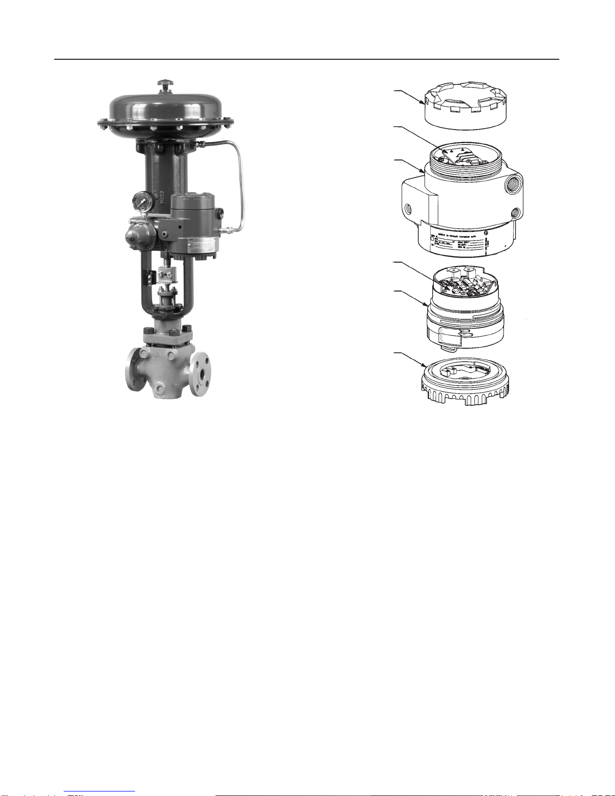
Type 846
2–1
Section2 Installation
When a control valve is ordered with a Type 846 trans-
ducer specified to be mounted on the actuator, the
factory-mounted transducer is connected to the actua-
tor with the necessary tubing and calibrated to the
specifications on the order.
If the transducer is purchased separately for mounting
on a control valve already in service, all the necessary
mounting parts are furnished, if ordered. This includes
the appropriate bracket for attaching the unit to an ac-
tuator boss (with tapped holes) or for attaching it to the
diaphragm casing.
If preferred, mounting parts can be supplied for mount-
ing the transducer on a 2-inch (51 mm) diameter pi-
pestand, a flat surface, or a bulkhead.
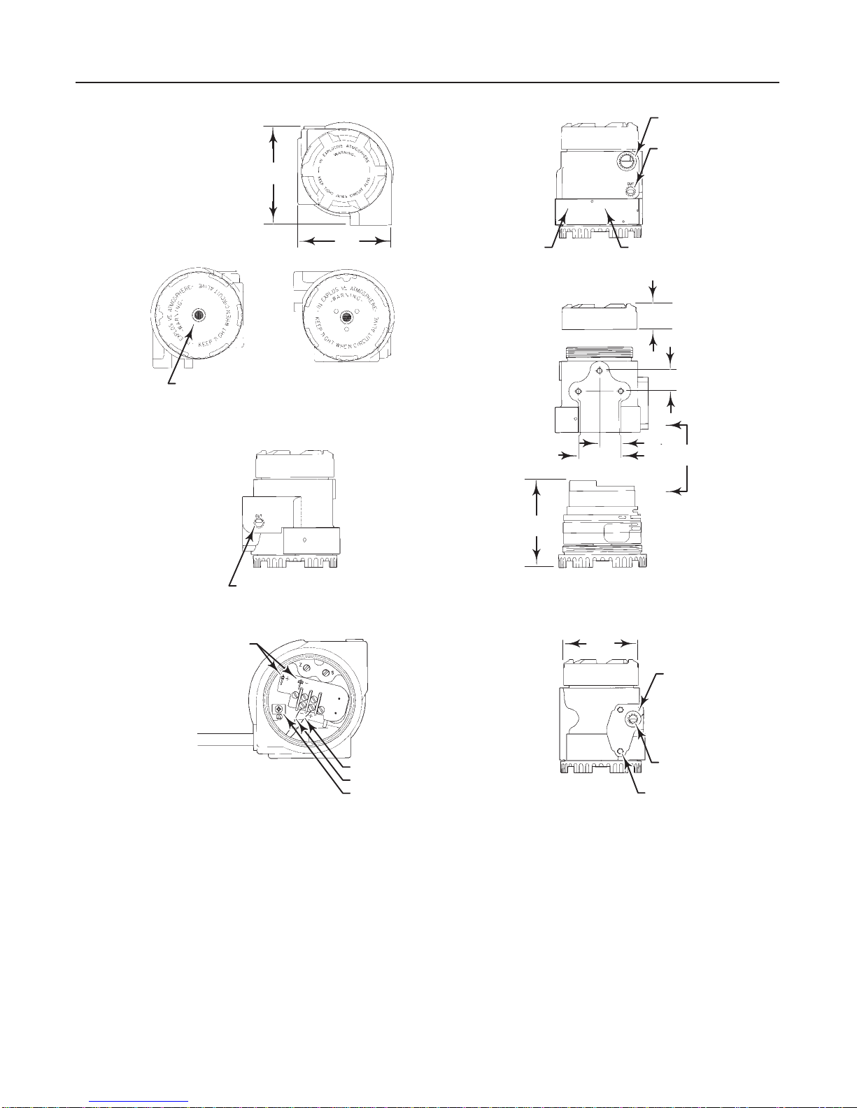
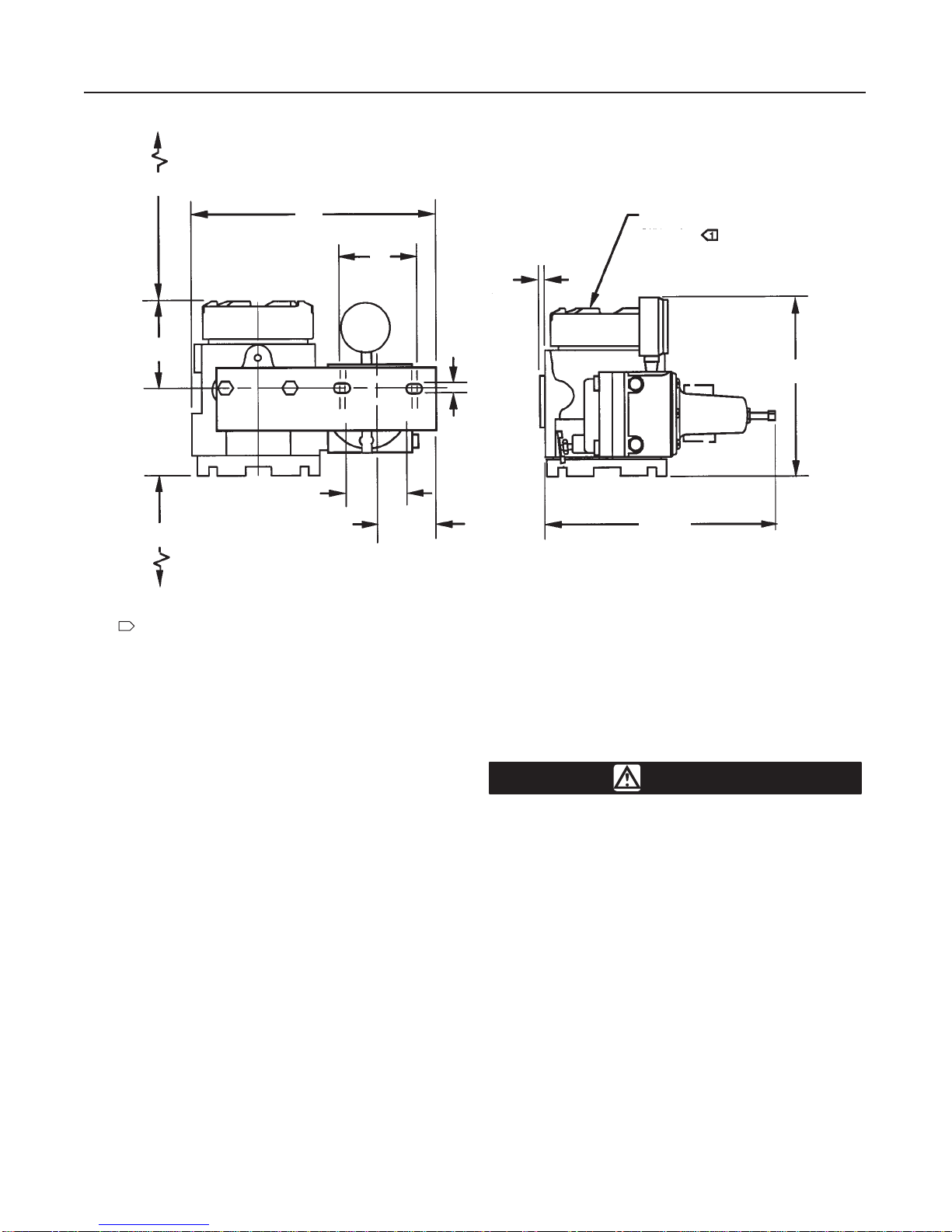
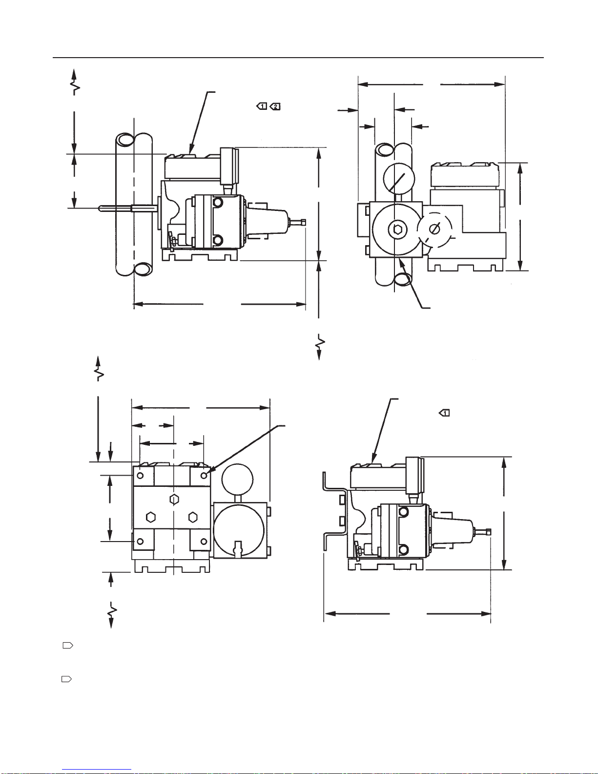
Mounting
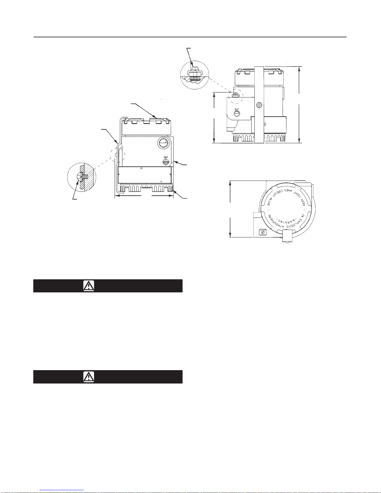
Figures 2-1, 2-2, and 2-NO TAG show the mounting
dimensions. Mount the unit with the stroke port down.
This allows any moisture buildup in the terminal
compartment to drain to the signal wire conduit en-
trance. Any moisture in the pilot stage area will be ex-
pelled through the stroke port without affecting pilot
stage operation. As an alternative, the Type 846 may
be mounted horizontally. However, it must be mounted
so that the flat bracket-mounting surface is down. In
applications with excessive moisture in the supply air,
vertical mounting allows the most effective drainage
through the stroke port.
Before mounting the Type 846, note the following rec-
ommendations:
DEnsurethatall bolts arefullytightened. The recom-
mended torque is 16 lbfSft (22 NSm).
DBolts that connect to the Type 846 and to a valve
actuator should have thelock washer placeddirectly be-
neath the bolt head and the flat washer placed between
the lock washer and bracket. All other boltsshould have
the lock washer next to the nut, and the flat washer
placed between the lock washer and bracket.
DDo not mount the Type 846 in a location where for-
eign material may cover the stroke port or exhaust port.
See the descriptions of the stroke port and exhaust port
later in this section.
Pressure Connections
As shown in figure 2-1, all pressure connections are
1/4-18 NPT female connections. Use 3/8-inch (9.5
mm) outside diameter tubing for the supply and output
connections.
Supply Pressure
WARNING
Personal injury or property damage may
occur from an uncontrolled process if
the supply medium is not clean, dry, oil-
free, or non-corrosive gas. Industry
instrument air quality standards de-
scribe acceptable dirt, oil, and moisture
content. Due to the variability in nature
of the problems these influences can
have on pneumatic equipment, Fisher
Controls has no technical basis to rec-
ommend the level of filtration equipment
required to prevent performance degra-
dation of pneumatic equipment. A filter
or filter regulator capable of removing
particles 40 microns in diameter should
suffice for most applications. Use of
suitable filtration equipment and the es-
tablishment of a maintenance cycle to
monitor its operations is recommended.
WARNING
Explosions may cause death or serious
injury. Do not operate the Type 846 with
the CENELEC flameproof options at a
supply pressure in excess of 20 psi (1.4
bar). Doing so invalidates the CENELEC
flameproof certifications and could al-
low flames to spread from the unit po-
tentially igniting and causing an explo-
sion.
The supply medium must be clean, dry air or noncor-
rosive gas that meets the requirements of ISA Stan-
dard S7.3-1975 (R1981). An output span of 3 to 15
psig (0.2 to 1.0 bar) requires a nominal supply pres-
sure of 20 psig (1.4 bar) and a flow capacity not less
than 4 SCFM (0.11 m3/min). For multirange perfor-
mance units with higher output spans, the supply pres-
sure should be at least 3 psig (0.2 bar) greater than
the maximum calibrated output pressure, but should
not exceed 35 psig (2.4 bar).
The air supply line can be connected to the 1/4–18
NPT supply port, or to the supply port of a filter-regula-
tor mounted directly to the transducer.
The mounting boss for the air supply connection con-
tains two 5/16–18 UNC tapped holes that are 2-1/4
inches apart. The tapped holes allow direct connection
of a filter-regulator having a matching through-bolt pat-
tern. A filter-regulator with mounting hardware is avail-
able. The mounting hardware consists of two 5/16–18
x 3-1/2 inch grade 5 bolts and one O-ring. See Table
6-1 for the O-ring size. The O-ring is positioned in the