Fisher 846 User manual

www.Fisher.com
Fisher™846 Current-to-Pressure Transducer
Contents
Introduction
Scope of Manual 2.............................
Description 2.................................
Specifications 2...............................
Educational Services 5.........................
Installation 6..................................
Hazardous Area Classifications and Special
Instructions for Safe‐Use and Installation
in Hazardous Locations 7.....................
Mounting 8..................................
Pressure Connections 8........................
Supply Pressure 10.........................
Output Pressure 14........................
Electrical Connections 14.......................
Venting Ports 15..............................
Signal Interruption 15..........................
Calibration 16..................................
Standard Performance:
Full Range Input, Direct Action 18.............
Multirange Performance:
Full Range Input, Direct Action 18.............
Standard Performance:
Split Range Input, Direct Action 19.............
4 to 12 mA Input Signal 19..................
12 to 20 mA Input Signal 19.................
Standard Performance:
Full Range Input, Reverse Action 20............
Multirange Performance:
Full Range Input, Reverse Action 20............
Standard Performance:
Split Range Input, Reverse Action 21...........
4 to 12 mA Input Signal 21..................
12 to 20 mA Input Signal 21.................
Transporting the Module Final Assembly 22.......
Principle of Operation 22........................
Electronic Circuit 22...........................
Magnetic Actuator 23..........................
Pilot Stage 23.................................
Booster Stage 24..............................
Troubleshooting 25.............................
Diagnostic Features 25.........................
Stroke Port 25.............................
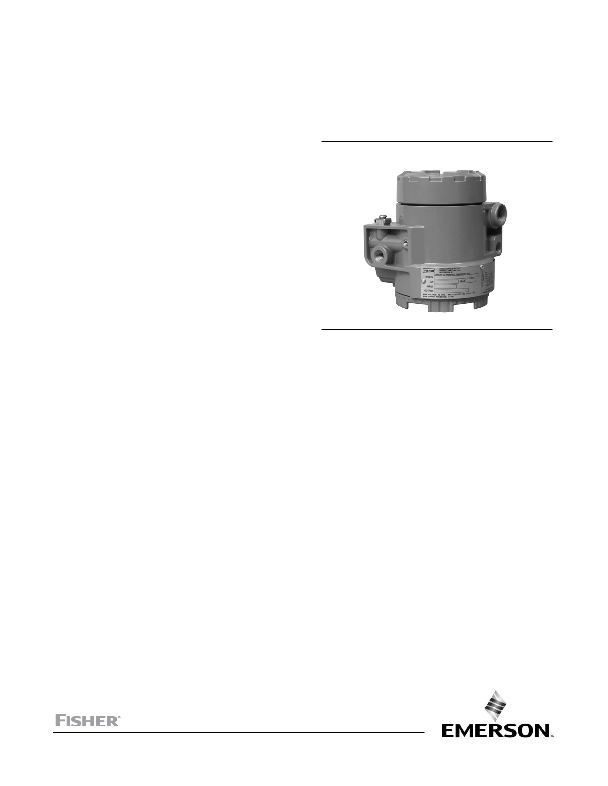
Figure 1. Fisher 846 Current‐to‐Pressure Transducer
X0234
Remote Pressure Reading (RPR) 25...........
Using a Frequency Counter to read the
RPR Signal 25.........................
In‐service Troubleshooting 26...................
Troubleshooting in the Shop 29.................
Maintenance 31................................
Module Final Assembly 32......................
Removing the Module Final Assembly 34......
Replacing the Module Final Assembly 35.......
Electronic Circuit Board 36......................
Remote Pressure Reading (RPR) Jumper 36.....
Range Jumper 37..........................
Action 37.................................
Removing the Electronic Circuit Board 37......
Replacing the Electronic Circuit Board 38......
Pilot/Actuator Assembly 38.....................
Action 38.................................
Removing the Pilot/Actuator Assembly 39.....
Replacing the Pilot/Actuator Assembly 39.....
Module Subassembly 40........................
Terminal Compartment 40.....................
Exhaust and Stroke Port Screens 41..............
Parts 42......................................
Instruction Manual
D102005X012
846 Transducer
June 2017

Instruction Manual
D102005X012
846 Transducer
June 2017
2
Introduction
Scope of Manual
This instruction manual provides installation, operating, calibration, maintenance, and parts ordering information for
Fisher 846 current‐to‐pressure transducers. Refer to separate manuals for instructions covering equipment used with
the transducers.
Do not install, operate or maintain an 846 current‐to‐pressure transducer without being fully trained and qualified in
valve, actuator, and accessory installation, operation, and maintenance. To avoid personal injury or property damage,
it is important to carefully read, understand, and follow all of the contents of this manual, including all safety cautions
and warnings. If you have any questions about these instructions, contact your Emerson sales office or Local Business
Partner before proceeding.
Description
The 846 current‐to‐pressure transducer, shown in figure 1, accepts an electrical input signal and produces a
proportional pneumatic output. Typically, 4 to 20 mA is converted to 0.2 to 1.0 bar (3 to 15 psi). Models are available
in direct or reverse action and field‐selectable for full or split range inputs. Refer to the Calibration section for more
information on input/output combinations.
The most common application of the transducer is to receive an electrical signal from a controller and produce a
pneumatic output for operating a control valve actuator or positioner. The 846 may also be used to produce a signal
for a pneumatic receiving instrument.
The 846 is an electronic I/P transducer. It has a single electronic circuit board, as shown in figure 2. The circuit contains
a solid‐state pressure sensor that monitors output pressure and is part of an electronic feedback network. The
self‐correcting ability provided by the sensor/circuit combination allows the transducer to produce a very stable and
responsive output signal.
All active mechanical and electrical components of the 846 are incorporated into a single, field‐replaceable module
called the module final assembly, shown in figure 2. The module final assembly contains the electronic circuit board,
pilot/actuator assembly, and booster stage. The module final assembly is easily removed by unscrewing the module
cover. Its design minimizes parts and reduces the time required for repair and troubleshooting.
The terminal compartment and module compartment are separated by a sealed compartment wall. This
multi‐compartment housing also protects the electronics from contaminants and moisture in the supply air.
Specifications
WARNING
This product is intended for a specific range of pressures, temperatures, and other application specifications. Applying
different pressure, temperature and other service conditions could result in a malfunction of the product, property damage
or personal injury.
Specifications for the 846 transducer are listed in table 1.

Instruction Manual
D102005X012
846 Transducer
June 2017
3
Table 1. Specifications
Input Signal
Standard Performance:
4 to 20 mA DC, 4 to 12 mA DC, or 12 to 20 mA DC.
Field adjustable split ranging.
Multirange Performance:
4 to 20 mA DC. Consult factory for split range input.
Equivalent Circuit
See figure 3
Output Signal(1)
Standard Performance:
(Consult factory for split range output)
Direct Action (Minimum span of 6 psi)
Typical outputs: 0.2 to 1.0 bar (3 to 15 psi).
Rangeability between 0.1 and 1.2 bar (1 and 18 psi)
Reverse Action (Minimum span of 11 psi)
Typical outputs: 1.0 to 0.2 bar (15 to 3 psi)
Rangeability between 1.2 and 0.1 bar (18 and 1 psi)
Multirange Performance:
Direct Action (Minimum span of 6 psi)
Typical outputs: 0.2 to 1.9 bar (3 to 27 psi), 0.4 to
2 bar (6 to 30 psi), and 0.3 to 1.7 bar (5 to 25 psi)
Rangeability between 0.03 and 2.3 bar (0.5 and
33 psi)
Reverse Action (Minimum span of 11 psi)
Typical outputs: 1.9 to 0.2 bar (27 to 3 psi), 2 to
0.4 bar (30 to 6 psi), and 1.7 to 0.3 bar (25 to 5 psi)
Rangeability between 2.3 and 0.03 bar (33 and
0.5 psi)
Supply Pressure(2)
Standard Performance: 1.2 to 1.6 bar (18 to 24 psi)
Multirange Performance:
0.2 bar (3 psi)(3) greater than the maximum
calibrated output pressure
Maximum: 2.4 bar (35 psi)
Supply Pressure Medium
Clean, dry air
Per ISA Standard 7.0.01
A maximum 40 micrometer particle size in the air
system is acceptable. Further filtration down to 5
micrometer particle size is recommended. Lubricant
content is not to exceed 1 ppm weight (w/w) or
volume (v/v) basis. Condensation in the air supply
should be minimized
Per ISO 8573-1
Maximum particle density size: Class 7
Oil content: Class 3
Pressure Dew Point: Class 3 or at least 10°C less than
the lowest ambient temperature expected
Output Air Capacity(4)
Standard: 6.4 m3/hr (240 scfh) at 1.4 bar
(20 psi) supply pressure
Multirange: 9.7 m3/hr (360 scfh) at 2.5 bar
(35 psig) supply pressure
Maximum Steady‐State Air Consumption(4)
0.3 m3/hr (12 scfh) at 1.4 bar (20 psi) supply pressure
Temperature Limits(2)
Operating: -40 to 85_C (-40 to 185_F)
Storage :-40 to 93_C (-40 to 200_F)
Humidity Limits
0 to 100% condensing relative humidity
Performance(5)
Note: The performance of all 846 I/Ps is verified
using computer automated manufacturing systems
to ensure that every unit shipped meets its
performance specifications.
Linearity, Hysteresis, and Repeatability: $0.3% of
span.
Temperature Effect (total effect including zero and
span): $0.07%/_C (0.045%/_F) of span
Vibration Effect: $0.3% of span per g during the
following conditions:
5 to 15 Hz at 4 mm constant displacement
15 to 150 Hz at 2 g. 150 to 2000 Hz at 1 g.
per SAMA Standard PMC 31.1, Sec. 5.3, Condition 3,
Steady State
Shock Effect: $0.5% of span, when tested per SAMA
Standard PMC 31.1, Sec. 5.4.
Supply Pressure Effect: Negligible
-Continued-

Instruction Manual
D102005X012
846 Transducer
June 2017
4
Table 1. Specifications (continued)
Performance (continued)(5)
Electromagnetic Interference (EMI): Tested per IEC
61326‐1:2013. Meets emission levels for Class A
equipment (industrial locations) and Class B
equipment (domestic locations). Meets immunity
requirements for industrial locations (Table A.1 in the
IEC specification document). Immunity performance
is shown in table 2.
Leak Sensitivity(4):Less than 1.0% of span for up to
4.8 m3/hr (180 scfh) downstream leakage.
Overpressure Effect: Less than 0.25% of span for
misapplication of up to 7.0 bar (100 psi) supply
pressure for less than 5 minutes to the input port.
Reverse Polarity Protection:
No damage occurs from reversal of normal supply
current (4 to 20 mA) or from misapplication of up to
100 mA.
Connections
Supply Air, Output Signal, and Output Gauge:
1/4‐18 NPT internal connection
Electrical: 1/2‐14 NPT internal conduit connection
Adjustments
Zero and Span: screwdriver adjustments located in
terminal compartment.
Remote Pressure Reading (RPR)
Jumper selectable, ON or OFF, if unit includes
option
Frequency Range: 0 to 10,000 Hz
Amplitude: 0.4 to 1.0 Vp‐p
Required Operating Voltage with Remote pressure
Reading Off
Min. 6.0 V (at 4 mA)
Max. 7.2 V (at 20 mA)
Required Operating Voltage with Remote Pressure
Reading On
Min 6.4 V (at 4 mA)
Max. 8.2 V (at 20 mA)
Electrical Classification
Hazardous area:
CSA C/US—Intrinsically Safe, Explosion-proof,
Non-Incendive
FM—Intrinsically Safe, Explosion-proof, Non-Incendive
ATEX—Intrinsically Safe, Flameproof, Type n
IECEx—Intrinsically Safe, Flameproof
Electrical Housing:
Tropicalization (Fungus test per MIL-STD-810)
CSA C/US—Type 4X
FM—Type 4X
ATEX—IP66(6)
IECEx—IP66(6)
Other Classifications/Certifications
INMETRO—National Institute of Metrology, Quality,
and Technology (Brazil)
KGS—Korea Gas Safety Corporation (South Korea)
NEPSI— National Supervision and Inspection Centre
for Explosion Protection and Safety of
Instrumentation (China)
Contact your Emerson sales office or Local Business
Partner for classification/certification specific
information
Construction Materials
Housing: Low‐copper aluminum with polyurethane
paint, or 316 stainless steel
O‐Rings: Nitrile, except silicone for sensor O‐rings.
Options
Fisher 67CFR filter regulator, supply and output
gauges or tire valve remote pressure reading, module
cover with multiple stroke ports, stainless steel
housing, or stainless steel mounting bracket.
Weight
Aluminum: 2.9 kg (6.5 lb) excluding options
Stainless Steel: 6.7 kg (14.8 lb) excluding options
-continued-

Instruction Manual
D102005X012
846 Transducer
June 2017
5
Table 1. Specifications (continued)
Declaration of SEP
Fisher Controls International LLC declares this
product to be in compliance with Article 3 paragraph
4 of the PED Directive 2014/68/EU. It was designed
and manufactured in accordance with Sound
Engineering Practice (SEP) and cannot bear the CE
marking related to PED compliance.
However, the product may bear the CE marking to
indicate compliance with other applicable European
Community Directives.
NOTE: Specialized instrument terms are defined in ANSI/ISA Standard 51.1 - Process Instrument Terminology.
1. Metric calibration also available.
2. The pressure/temperature limits in this document, and any applicable standard or code limitation should not be exceeded.
3. 0.14 bar (2 psi) for a 2.3 bar (33 psi) output.
4. Normal m3/hr—Normal cubic meters per hour (0_C and 1.01325 bar, absolute). Scfh—Standard cubic feet per hour (60_F and 14.7 psia).
5. Reference Conditions: 4.0 to 20 mA DC input, 0.2 to 1.0 bar (3 to 15 psi) output, and 1.4 bar (20 psi) supply pressure.
6. ATEX and IECEx Flameproof — IP66 per CSA Letter of Attestation.
Table 2. EMC Immunity Performance Criteria
Port Phenomenon Basic Standard Test Level Performance Criteria(1)
Enclosure
Electrostatic discharge (ESD) IEC 61000‐4‐2 4 kV contact
8 kV air A
Radiated EM field IEC 61000‐4‐3
80 to 1000 MHz @ 10V/m with 1 kHz AM at 80%
1400 to 2000 MHz @ 3V/m with 1kHz AM at 80%
2000 to 2700 MHz @ 1V/m with 1kHz AM at 80%
A
I/O signal/control
Burst (fast transients) IEC 61000‐4‐4 1 kV A
Surge IEC 61000‐4‐5 1 kV (line to ground only, each) B
Conducted RF IEC 61000‐4‐6 150 kHz to 8 MHz at 3 Vrms B
8 MHz to 80 MHz at 3 Vrms A
Specification limit = ±1% of span
1. A = No degradation during testing. B = Temporary degradation during testing, but is self‐recovering.
Educational Services
For information on available courses for the 846 current‐to‐pressure transducer, as well as a variety of other products,
contact:
Emerson Automation Solutions
Educational Services - Registration
Phone: +1-641-754-3771 or +1-800-338-8158
Email: [email protected]
emerson.com/fishervalvetraining

Instruction Manual
D102005X012
846 Transducer
June 2017
6
Figure 2. Transducer Modular Construction
A6643
MODULE COVER
MODULE FINAL
ASSEMBLY
ELECTRONIC
CIRCUIT BOARD
MODULE HOUSING
TERMINAL BLOCK
TERMINAL
COMPARTMENT
COVER
Figure 3. Equivalent Circuit
NOTE:
THE 846 IS NOT A CONSTANT RESISTOR IN SERIES WITH AN INDUCTOR. IT IS BETTER
MODELED IN THE LOOP AS A 50 OHM RESISTOR IN SERIES WITH A 6‐VOLT DC VOLTAGE
DROP WITH NEGLIGIBLE INDUCTANCE.
A6325
846
6 V DC
50
OHMS
POWER
SUPPLY
Installation
WARNING
To avoid personal injury or property damage from the sudden release of pressure or air:
D Always wear protective clothing, gloves, and eyewear when performing any installation operations.
D Disconnect any operating lines providing air pressure, electric power, or a control signal to the actuator. Be sure the
actuator cannot suddenly open or close the valve.
D Use bypass valves or completely shut off the process to isolate the valve from process pressure. Relieve process pressure
on both sides of the valve.
D Use lock‐out procedures to be sure that the above measures stay in effect while you work on the equipment.
D Check with your process or safety engineer for any additional measures that must be taken to protect against process
media.

Instruction Manual
D102005X012
846 Transducer
June 2017
7
CAUTION
Do not use sealing tape on pneumatic connections. This instrument contains small passages that may become obstructed
by detached sealing tape. Thread sealant paste should be used to seal and lubricate pneumatic threaded connections.
This section presents information on installing the 846 current‐to‐pressure transducer. Figures 4, 5, 6, and 8 can be
used as references for instructions contained in this section.
When a control valve is ordered with an 846 transducer specified to be mounted on the actuator, the factory‐mounted
transducer is connected to the actuator with the necessary tubing and calibrated to the specifications on the order.
If the transducer is purchased separately for mounting on a control valve already in service, all the necessary mounting
parts are furnished, if ordered. This includes the appropriate bracket for attaching the unit to an actuator boss (with
tapped holes) or for attaching it to the diaphragm casing.
If preferred, mounting parts can be supplied for mounting the transducer on a 51 mm (2‐inch) diameter pipestand, a
flat surface, or a bulkhead.
Transducers also can be ordered separately for mounting on a control valve assembly already in service. The
transducer may be ordered with or without mounting parts. Mounting parts include the appropriate bracket and bolts
for attaching the unit to an actuator boss (with tapped holes) or for attaching it to the diaphragm casing.
Hazardous Area Classifications and Special Instructions for “Safe Use” and
Installation in Hazardous Locations
Refer to the following instruction manual supplements for approval information.
D CSA Approval Information for Fisher 846 Current-to-Pressure Transducers (D104218X012)
D FM Approval Information for Fisher 846 Current-to-Pressure Transducers (D104219X012)
D ATEX Approval Information for 846 Current-to-Pressure Transducers (D104220X012)
D IECEx Approval Information for 846 Current-to-Pressure Transducers (D104221X012)
D INMETRO Approval Information for Fisher 846 Current-to-Pressure Transducers (D103623X012)
D NEPSI Approval Information for Fisher 846 Current-to-Pressure Transducers (D103618X012)
All documents are available from your Emerson sales office, Local Business Partner, or Fisher.com. Contact your
Emerson sales office or Local Business Partner for all other approval/certification information.

Instruction Manual
D102005X012
846 Transducer
June 2017
8
Mounting
WARNING
This unit will vent to the atmosphere through the stroke port in the module cover and the exhaust port, located under the
nameplate. Do not remote vent this unit.
The transducer is designed for mounting on a control valve, 51 mm (2‐inch) diameter pipestand, wall, or panel. Figures
5, 6, 7, and 8 show recommended mounting configurations. The mounting positions shown allow any moisture
buildup in the terminal compartment to drain to the signal wire conduit entrance. Any moisture in the pilot stage area
will be expelled through the stroke port without affecting pilot stage operation. In applications with excessive
moisture in the supply air, vertical mounting allows the most effective drainage through the stroke port.
CAUTION
Do not mount the transducer with the terminal compartment cover on the bottom as moisture, or any corrosive elements
in the plant atmosphere, may accumulate in the terminal compartment or pilot stage, resulting in transducer malfunction.
Mounting is accomplished with an optional universal mounting bracket. Before mounting the transducer, note the
following recommendations:
D Ensure that all bolts are fully tightened. The recommended torque is 22 NSm (16 lbfSft).
D Bolts that connect to the transducer and to a valve actuator should have the lock washer placed directly beneath the
bolt head and the flat washer placed between the lock washer and bracket. All other bolts should have the lock
washer next to the nut, and the flat washer placed between the lock washer and bracket.
D Do not mount the transducer in a location where foreign material may cover the stroke port or exhaust port. See the
descriptions of the stroke port and exhaust port later in this section.
Pressure Connections
CAUTION
Do not use sealing tape on pneumatic connections. This instrument contains small passages that may become obstructed
by detached sealing tape. Thread sealant paste should be used to seal and lubricate pneumatic threaded connections.
As shown in figure 4, all pressure connections are 1/4‐18 NPT internal connections. Use 9.5 mm (3/8‐inch) outside
diameter tubing for the supply and output connections.

Instruction Manual
D102005X012
846 Transducer
June 2017
9
Figure 4. Typical Dimensions and Connection Locations (Aluminum Construction Shown)
129
(5.07)
119
(4.68)
STROKE PORT
OUTPUT GAUGE PORT 1/4‐18 NPT
NAMEPLATE EXHAUST PORT
UNDERNEATH NAMEPLATE
CONDUIT CONNECTION
1/2 ‐ 14 NPT
OUTPUT PORT
1/4 ‐ 18 NPT
MODULE COVER WITH
MULTIPLE PORTS
WIRING CONNECTION
35
(1.38)
29
(1.13)
59
(2.31) COVER
REMOVAL
110
(4.33)
102
(4.00)
5/16‐18 (2)
O‐RING GROOVE
FOR FILTER REGULATOR
SUPPLY PORT 1/4‐18 NPT
POSITIVE
NEGATIVE
INTERNAL GROUND
mm
(INCHES)
B2473‐1
TEST PINS
29
(1.16)
NOTE:
REFER TO FIGURE 8 FOR TRANSDUCER DIMENSIONS WITH
ATEX / IECEx FLAMEPROOF CERTIFICATIONS
MOUNTING BOLT
HOLES 5/16‐18 (3)

Instruction Manual
D102005X012
846 Transducer
June 2017
10
Supply Pressure
WARNING
Severe personal injury or property damage may occur from process instability if the instrument supply medium is not
clean, dry air. While use and regular maintenance of a filter that removes particles larger than 40 micrometers in diameter
will suffice in most applications, check with an Emerson Automation Solutions field office and industry instrument air
quality standards if you are unsure about the proper amount or method of air filtration or filter maintenance.
The supply medium must be clean, dry air that meets the requirements of ISA Standard 7.0.01 or ISO 8573-1. An
output span of 0.2 to 1.0 bar (3 to 15 psi) requires a nominal supply pressure of 1.4 bar (20 psi) and a flow capacity not
less than 6.4 normal m3/hr (240 scfh).
For multirange performance units with higher output spans, the supply pressure should be at least 0.2 bar (3 psi)
greater than the maximum calibrated output pressure.
The air supply line can be connected to the 1/4‐18 NPT supply port, or to the supply port of a filter‐regulator mounted
directly to the transducer. Figures 5, 6, 7, and 8 show the installation options.
Figure 5. Typical Dimensions with Fisher 67CFR Filter/Regulator and Gauges
6
(0.25)
COVER
REMOVAL
CLEARANCE
MODULE
COVER
REMOVAL
CLEARANCE
FOR PROPER MOISTURE DRAINAGE
THIS END MUST BE UP
67
(2.62)
78
(3.08)
CENTERLINE
OF ACTUATOR
191
(7.51)
137
(5.38)
YOKE MOUNTED
NOTE:
1 THE MOUNTING POSITIONS SHOWN ALLOW ANY MOISTURE BUILDUP IN THE TERMINAL COMPARTMENT
TO DRAIN TO THE SIGNAL WIRE CONDUIT ENTRANCE. DO NOT MOUNT THE TRANSDUCER WITH THE TERMINAL
COMPARTMENT COVER ON THE BOTTOM; MOISTURE MAY ACCUMULATE IN THE TERMINAL COMPARTMENT
OR PILOT STAGE, PREVENTING PROPER TRANSDUCER OPERATION. THE VERTICAL MOUNT IS MOST EFFECTIVE
FOR MOISTURE DRAINAGE IN WET APPLICATIONS.
14B7361‐D
A6626-3
mm
(INCH)
13
(0.50)
156
(6.15)
1
215
(8.48)
FOR ATEX/IECEx
FLAMEPROOF UNITS:
BOLT ENGAGEMENT
NOT TO EXCEED
12.9 mm (0.51 INCHES).
5/16‐18 BOLTS

Instruction Manual
D102005X012
846 Transducer
June 2017
11
Figure 6. Typical Transducer Mounting with Universal Mounting Bracket
32
(1.25)
FOR PROPER
MOISTURE
DRAINAGE,
THIS END
MUST BE UP
5/16‐18 x 3/4 BOLTS
(4 PLACES)
MOUNTING BRACKET (SEE DETAIL “A”)
5/16‐18 x 3/4 BOLTS (4 PLACES)
5/16‐18 HEX NUT (4 PLACES)
ADAPTER PLATE
(SEE DETAIL “B”)
MOUNTING BRACKET
(SEE DETAIL “A”)
FOR PROPER MOISTURE
DRAINAGE, THE I/P
MUST BE MOUNTED ON
TOP OF THE PIPE
5/16‐18 x 5/8
BOLTS
FOR PROPER MOISTURE
DRAINAGE, THIS END
MUST BE UP
ADAPTER PLATE
(SEE DETAIL “B”)
MOUNTING BRACKET
(SEE DETAIL “A”)
41
(1.61)
U BOLT
VERTICAL MOUNT
ADDITIONAL ADAPTER PLATE
PART NUMBER 03311‐0318‐0001
REQUIRED FOR I/P WITH
STAINLESS STEEL HOUSING
3
HORIZONTAL MOUNT
2
ADDITIONAL ADAPTER
PLATE PART NUMBER
03311‐0318‐0001
REQUIRED FOR I/P
WITH STAINLESS STEEL
HOUSING
2‐INCH PIPESTAND MOUNTING
NOTES:
1 THE MOUNTING POSITIONS SHOWN ALLOW ANY MOISTURE BUILDUP IN THE TERMINAL COMPARTMENT
TO DRAIN TO THE SIGNAL WIRE CONDUIT ENTRANCE. DO NOT MOUNT THE TRANSDUCER WITH THE TERMINAL
COMPARTMENT COVER ON THE BOTTOM; MOISTURE MAY ACCUMULATE IN THE TERMINAL COMPARTMENT
OR PILOT STAGE, PREVENTING PROPER TRANSDUCER OPERATION. THE VERTICAL MOUNT IS MOST EFFECTIVE
FOR MOISTURE DRAINAGE IN WET APPLICATIONS.
2 IF MOUNTED ON HORIZONTAL PIPE, THE I/P MUST BE ON TOP OF THE PIPE FOR PROPER MOISTURE DRAINAGE.
3 THIS DIMENSION IS 44 (1.74) FOR STAINLESS STEEL HOUSING.
14B7332
19B9484‐B
E0786
mm
(INCH)
1
11
WALL/PANEL MOUNTING
(ALUMINUM HOUSING)
GE06214 SHT 3
GE06214 SHT 2
BOLT HOLES FOR ALUMINUM
CONSTRUCTION (COVERLOCK SHOWN)
BOLT HOLES FOR STAINLESS
STEEL CONSTRUCTION
(COVERLOCK SHOWN)
FOR ATEX/IECEx
FLAMEPROOF UNITS:
BOLT ENGAGEMENT
NOT TO EXCEED
8.1 mm (0.32 INCHES).
5/16‐18 BOLT HOLES
FOR ATEX/IECEx FLAMEPROOF
UNITS: BOLT ENGAGEMENT NOT TO
EXCEED 8.8 mm (0.35 INCHES).
5/16‐18 BOLT HOLES

Instruction Manual
D102005X012
846 Transducer
June 2017
12
Figure 6. Typical Transducer Mounting with Universal Mounting Bracket (continued)
mm
(INCH)
30
(1.18)
23
(.89)
4 X 10 (0.375)
5 X 10 (0.375)
89
(3.50)
89
(3.50)
59
(2.312)
29
(1.16)
29
(1.13)
38
(1.50)
U‐BOLT SLOTS
19 (0.75)
29
(1.125 57
(2.25)
2 X 10 (0.375)
4 X 5 (0.188)
DETAIL “A” MOUNTING BRACKET
DETAIL “B” ADAPTER PLATE
FOR STAINLESS STEEL HOUSING,
ALIGN 4 HOLES WITH I/P HOUSING
FOR ALUMINUM HOUSING,
ALIGN 3 HOLES WITH I/P HOUSING
NOTES:
1. ATTACH THE BRACKET SHOWN IN DETAIL “A” TO THE TRANSDUCER
2. ATTACH THE ADAPTER PLATE SHOWN IN DETAIL “B” TO THE VALVE OR PIPE.
3. CONNECT THE TWO PIECES.
34B4990‐C
34B5000‐B
E0787
ADDITIONAL ADAPTOR PLATE (PART NUMBER 03311‐0318‐0001)
REQUIRED FOR I/P WITH STAINLESS STEEL HOUSING
38
(1.50)
U‐BOLT SLOTS
19 (0.75)
29
(1.125 57
(2.25)
2 X 10 (0.375)
4 X 5 (0.188)
03311-0318
The mounting boss for the air supply connection contains two 5/16‐18 UNC tapped holes that are 2‐1/4 inches apart.
The tapped holes allow direct connection (integral mount) of a 67CFR filter‐regulator, if desired. When the
filter‐regulator is factory mounted, the mounting hardware consists of two 5/16‐18 x 3‐1/2 inch stainless steel bolts
and one O‐ring. When the filter‐regulator is field mounted, the mounting hardware consists of two 5/16‐18 x 3‐1/2
inch stainless steel bolts, two spacers (which may or may not be required) and two O‐rings (of which only one will fit
correctly into the housing O‐ring groove and the other may be discarded). This is due to the fact that the current
housing has been slightly modified from its original design, hence, the additional hardware (if needed) when field
mounting the 67CFR filter‐regulator.

Instruction Manual
D102005X012
846 Transducer
June 2017
13
Figure 7. Typical Transducer Dimensions with Gauges
SUPPLY
GAGE
49
(1.92)
72
(2.83) 9
(0.36)
81
(3.2)
OUTPUT GAGE
FILTER‐
REGULATOR
14B7332‐D
E0776
1/4‐18 NPT
OUTLET CONN
PLUGGED WHEN
GAUGE NOT
FURNISHED
67CFR
14‐18 NPT
SUPPLY CONN
mm
(INCH)
Figure 8. Transducer Dimensions with ATEX / IECEx Flameproof Certifications
TERMINAL
COMPARTMENT
COVER
COVER LOCK
INTERNAL
HEX DRIVE
ROUND HEAD
SCREW (3 mm)
4.75
(121) MODULE COVER
HOUSING
EXTERNAL EARTHING CONNECTION, SST TERMINAL
CLAMP AND SLOTTED M5 SCREW AND SPLIT RING WASHER
3.62
(92)
162
(6.38)
121
(4.75)
mm
(INCH)
B2465
129
(5.07)

Instruction Manual
D102005X012
846 Transducer
June 2017
14
Output Pressure
Connect the output signal line to the transducer at the output port. The output port is 1/4‐18 NPT, as shown in figure
4. The output gauge port can be used as an alternate signal port. If the gauge port is used as a signal port, a threaded
plug must be installed in the output port.
The output gauge port allows connection of an output gauge to provide local output signal indication. The output
gauge port is 1/4‐18 NPT. If an output gauge is not specified, a threaded plug is shipped with the transducer. The plug
must be installed in the output gauge port when the port is not used.
Electrical Connections
WARNING
Personal injury or property damage could result from fire or explosion. In explosive atmospheres, remove power and shut
off the air supply to the I/P unit before attempting to remove the terminal compartment cover or module cover. Failure to
do so could result in an electrical spark or explosion.
Personal injury or property damage could result from an uncontrolled process. Perform the steps in the WARNING at the
beginning of the Installation section before removing the module cover to ensure the process is properly controlled.
Unscrewing the module cover removes power from the electronics and opens the supply and output air passages to
atmosphere resulting in an output signal of 0.0 psi.
CAUTION
Excessive current can damage the transducer. Do not connect an input current of more than 100 mA to the transducer.
Note
For North American explosion‐proof applications, 846 transducers have been designed so that a conduit seal is not required. For all
other applications install the product per local, regional, or national code, rules, and regulations.
WARNING
Select wiring and/or cable glands that are rated for the environment of use (such as hazardous location, ingress protection,
and temperature). Failure to use properly rated wiring and/or cable glands can result in personal injury or property damage
from fire or explosion.
Signal wiring is brought to the terminal compartment through a 1/2‐14 NPT housing conduit connection, shown in
figure 4. Where condensate is common, use a conduit drip leg to help reduce liquid buildup in the terminal
compartment and avoid shorting of the input signal. Electrical connections are made at the terminal block. Internal
and external grounding lugs are provided to facilitate a separate ground when required. The internal ground is shown
in figure 4, and the external grounding lug is shown in figure 8.

Instruction Manual
D102005X012
846 Transducer
June 2017
15
Connect the positive signal lead to the positive terminal, marked +. Connect the negative signal lead to the negative
terminal, marked -.
Note
Units with the Remote Pressure Reading (RPR) option may cause interference with the analog output signal from some
instrumentation systems. This problem may be solved by placing a 0.2 microfarad capacitor or a HART filter across the output
terminals.
Venting Ports
WARNING
This unit will vent to the atmosphere through the stroke port in the module cover and the exhaust port, located under the
nameplate. Do not remote vent this unit.
Stroke Port
The constant bleed of supply medium from the pilot stage is directed out the stroke port, which is a screened hole
located at the center of the module cover. Figure 4 shows the location of the stroke port.
Before installing the transducer, ensure the stroke port is clear. Do not mount the transducer in a location where
foreign material may cover the stroke port. For information on using the stroke port, refer to the Troubleshooting
section.
Exhaust Port
The transducer exhausts through a screened port located beneath the instrument nameplate. Figure 4 shows the
location of the exhaust port. The nameplate holds the screen in place. Exhaust will occur with a reduction in output
pressure. The transducer should not be mounted in a location where foreign material may clog the exhaust port.
Signal Interruption
Upon loss of input current, or if input current decreases below 3.3 $0.3 mA, the output of the direct action unit will
decrease to less than 0.1 bar (1 psi).
In the same situation, the output of the reverse action unit will increase to near supply pressure.

Instruction Manual
D102005X012
846 Transducer
June 2017
16
Calibration
WARNING
The following calibration procedures require taking the transducer out of service. To avoid personal injury and property
damage caused by an uncontrolled process, provide some temporary means of control for the process before taking the
transducer out of service. Also refer to the WARNING at the beginning of the Maintenance section.
Calibration of the 846 requires either an accurate current generator or an accurate voltage generator with a precision
250‐ohm, 1/2‐watt resistor. Figure 9 shows how to connect either device.
Calibration also requires a precision output indicator and a minimum non-surging air supply of 5.0 normal m3/hr
(187 scfh) at 1.4 bar (20 psi) for standard performance units. For multirange performance units, the air supply must be
at least 0.2 bar (3 psi) greater than the maximum calibrated output pressure, up to 2.4 bar (35 psi) maximum.
For ease of calibration, the output load volume, including the output tubing and output indicator, should be a
minimum of 33 cm3(2 cubic inches). Review the information under Signal Interruption in the Installation section
before beginning the calibration procedure.
Before calibration, determine the type of input (full or split range), and the type of output action (direct or reverse).
Consult the factory for split range output calibration. Also, determine if the unit offers standard or multirange
performance. The unit supports eight basic input/output combinations:
Standard Performance
D Full Range Input, Direct Action
D Split Range Input, Direct Action
D Full Range Input, Reverse Action
D Split Range Input, Reverse Action
Multirange Performance
D Full Range Input, Direct Action
D Split Range Input, Direct Action (see note below)
D Full Range Input, Reverse Action
D Split Range Input, Reverse Action (see note below)
Note
Consult your Emerson sales office or Local Business Partner for calibration of multirange performance units with split range input
or split range output, or both.

Instruction Manual
D102005X012
846 Transducer
June 2017
17
Figure 9. Connecting a Current or Voltage Source for Calibration
ADJUST THE CURRENT
SOURCE TO PROVIDE
THE 4 AND 20 mA
SET POINTS
CALIBRATION USING A CURRENT SOURCE CALIBRATION USING A VOLTAGE SOURCE
TO OBTAIN THE 4 AND 20 mA
SET POINTS, ADJUST THE
VOLTAGE SOURCE (VS) SO
THE VOLTMETER (VM) READS
1 AND 5 VOLTS, RESPECTIVELY,
ACROSS THE 250 ohm RESISTOR
A6644‐1
CAUTION
Excessive current can damage the transducer. Do not connect an input current of more than 100 mA to the transducer.
Table 3 lists the various input and output ranges over which the unit may be calibrated.
The input range is selected by changing the position of a jumper located on the electronic circuit board.
Refer to Electronic Circuit Board in the Maintenance section, and figure 18 for the location and instruction on
placement.
Table 3. Fisher 846 I/P Rangeability Matrix
Input
Range
Output Pressure Range (psi) (Performance Code)
Common Ranges Misc. Std. Split High Range Splits
3-15
(S,M)
.5-30
(M)
3-27
(M)
6-30
(M)
5-25
(M)
0.5-6
(S,M)
.5-18
(S,M)
3-9
(S,M)
9-15
(S,M)
.5-15
(S,M)
15-30
(M)
15-27
(M)
6-18
(S,M)
18-30
(M)
5-15
(S,M)
15-25
(M)
4-20 nnnnn DnD D nU U nUnU
4-12
12-20
n
n
n n
J
n
J
n
J
D
D
n
J
D
D
D
D
n
J
U
n
U
n
n
n
U
n
n
n
U
n
4-8
8-12
12-16
16-20
n
n
J
J
n
n
J
J
n
n
J
J
n
n
n
J
n
n
J
J
n
n
J
J
S=Standard Performance Unit
M=Multirange Performance Unit
n=Available in Direct or Reverse Action
D=Available in Direct Action Only
J=Available, but if the desired calibration cannot be achieved by adjusting the zero/span screws, unit may require Hi/Lo jumper to be moved. The jumper is located on the circuit board assembly,
and is usually in the Hi position. Disengaging the master module and moving the jumper to the Lo position will allow calibration to the desired range.
U=Special Build Required.

Instruction Manual
D102005X012
846 Transducer
June 2017
18
Standard Performance: Full Range Input, Direct Action
WARNING
Refer to the WARNING at the beginning of the Maintenance section.
Use the following procedure to achieve a standard 0.2 to 1.0 bar (3 to 15 psi) output span for a 4 to 20 mA input signal:
1. Remove the module final assembly from the housing. Refer to Removing the Module Final Assembly in the
Maintenance section for an explanation of how to disengage the module final assembly.
2. Confirm that the unit is direct acting. A green electronic circuit board identifies direct‐acting units. Refer to Action
under the heading Electronic Circuit Board in the Maintenance section for more information on direct acting units.
3. Position the range jumper in the Hi position for High Range. Figure 18 shows the circuit board jumper positions.
4. Replace the module final assembly in the housing. Refer to Replacing the Module Final Assembly in the
Maintenance section for an explanation of how to engage the module final assembly.
5. Connect the air supply to the air supply port.
6. Connect a precision output indicator to the output signal port.
7. Make sure that the output gauge port has an output gauge or a threaded plug installed. A threaded plug is provided
for units shipped without output gauges.
8. Remove the terminal compartment cover.
9. Connect the current source (or voltage source) positive lead (+) to the terminal block positive (+) and the current
source (250‐ohm resistor lead) negative lead (-) to the terminal block negative (-). Refer to figure 9.
CAUTION
Excessive current can damage the transducer. Do not connect an input current of more than 100 mA to the transducer.
10. Apply a 4.0 mA (Vm = 1.0 V) signal, and adjust the zero screw to achieve a 0.2 bar (3.0 psi) output. The output
increases with clockwise rotation of the zero screw.
11. Apply a 20.0 mA (Vm = 5.0 V) signal, and adjust the span screw to achieve a 1.0 bar (15.0 psi) output. The output
increases with clockwise rotation of the span screw.
12. Repeat steps 10 and 11 to verify and complete the calibration.
Multirange Performance: Full Range Input, Direct Action
WARNING
Refer to the WARNING at the beginning of the Maintenance section.
Note
Consult your Emerson sales office or Local Business Partner for calibration of multirange performance units with split range input.

Instruction Manual
D102005X012
846 Transducer
June 2017
19
Use the following procedure with a multirange performance unit to achieve the desired direct action output span for a
4 to 20 mA input signal:
1. Perform steps 1 through 9 of the calibration procedure for Standard Performance: Full Range Input, Direct Action.
2. Apply a 4.0 mA (Vm = 1.0 V) signal, and adjust the zero screw to achieve the desired lower limit of the output range.
The lower limit must be between 0.03 and 0.6 bar (0.5 and 9.0 psi). The output increases with clockwise rotation of
the zero screw.
3. Apply a 20.0 mA (Vm = 5.0 V) signal, and adjust the span screw to achieve the desired upper limit of the output
range. The span must be at least 0.4 bar (6.0 psi). The maximum upper limit is 2.0 bar (30.0 psi). The output
increases with clockwise rotation of the span screw.
4. Repeat steps 2 and 3 to verify and complete the calibration.
Standard Performance: Split Range Input, Direct Action
WARNING
Refer to the WARNING at the beginning of the Maintenance section.
4 to 12 mA Input Signal
Use the following calibration procedure to produce a 0.2 to 1.0 bar (3 to 15 psi) output span for a 4 to 12 mA input
signal:
1. Perform steps 1 through 9 of the calibration procedure for Standard Performance: Full Range Input, Direct Action.
2. Apply an input of 4.0 mA (Vm = 1.0 V), and adjust the zero screw to achieve an output of 0.2 bar (3.0 psi).
3. Apply an input of 12.0 mA (Vm = 3.0 V), and adjust the span screw to achieve an output of 1.0 bar (15.0 psi).
4. Repeat steps 2 and 3 to verify and complete the calibration.
12 to 20 mA Input Signal
Use the following calibration procedure to produce a 0.2 to 1.0 bar (3 to 15 psi) output span for a 12 to 20 mA input
signal:
Note
There may be some span interaction with zero in this range, and the following steps compensate for this.
1. Perform steps 1 through 9 of the calibration procedure for Standard Performance: Full Range Input, Direct Action.
2. Apply an input of 4.0 mA (Vm = 1.0 V), and adjust the zero screw to achieve an output of 0.2 bar (3.0 psi).
3. Apply an input of 12.0 mA (Vm = 3.0 V), and adjust the span screw to achieve an output of 1.0 bar (15.0 psi).
4. Maintain the input of 12.0 mA (Vm = 3.0 V), and adjust the zero screw to achieve an output of 0.2 bar (3.0 psi). The
unit may not turn down this low; if it does not, go to step 7.
5. If the output reaches 0.2 bar (3.0 psi) in step 4, apply an input of 20.0 ma (Vm = 5.0 V) and note the error (the actual
reading versus 15.0 psi). Adjust the span screw to overcorrect the error by a factor of two. For example, if the
reading was 0.9 bar (14.95 psi), adjust the span screw to achieve an output of 1.1 bar (15.05 psi).

Instruction Manual
D102005X012
846 Transducer
June 2017
20
6. Repeat steps 4 and 5 to verify and complete the calibration.
7. Turn off the air supply. Remove the module final assembly from the housing. Place the range jumper in the Lo
position for Low Range, as indicated in figure 18. Replace the module final assembly. Turn on the air supply.
8. Apply an input of 12.0 mA (Vm = 3.0 V), and adjust the zero screw to achieve an output of 0.2 bar (3.0 psi).
9. Apply an input of 20.0 mA (Vm = 5.0 V), and note the error (the actual reading versus 15.0 psi). Adjust the span
screw to overcorrect the error by a factor of two. For example, if the reading was 0.9 bar (14.95 psi), adjust the span
screw to achieve an output of 1.1 bar (15.05 psi).
10. Repeat steps 8 and 9 to verify and complete the calibration.
Standard Performance: Full Range Input, Reverse Action
WARNING
Refer to the WARNING at the beginning of the Maintenance section.
Use the following procedure on reverse action units to achieve a 1.0 to 0.2 bar (15 to 3 psi) output span for a 4 to 20
mA input signal:
1. Perform steps 1 through 9 under Standard Performance: Full Range Input, Direct Action, except for step 2. In place
of step 2, confirm that the unit is reverse acting. A blue electronic circuit board identifies reverse‐acting units. Refer
to Action under the heading Electronic Circuit Board in the Maintenance section for more information on reverse
acting units.
2. Apply an input of 4.0 mA (Vm = 1.0 V), and adjust the zero screw to achieve an output of 1.0 bar (15.0 psi).
3. Apply an input of 20.0 mA (Vm = 5.0 V), and adjust the span screw to achieve an output of 0.2 bar (3.0 psi).
4. Repeat steps 2 and 3 to verify and complete the calibration.
Multirange Performance: Full Range Input, Reverse Action
WARNING
Refer to the WARNING at the beginning of the Maintenance section.
Note
Consult your Emerson sales office or Local Business Partner for calibration of multirange performance units with split range input.
Use the following procedure with a multirange unit to achieve the desired reverse action output span for a 4 to 20 mA
input signal:
1. Perform steps 1 through 9 of the calibration procedure for Standard Performance: Full Range Input, Direct Action,
except for step 2. In place of step 2, confirm that the unit is reverse acting. A blue electronic circuit board identifies
reverse‐acting units. Refer to Action under the heading Electronic Circuit Board in the Maintenance section for more
information on reverse acting units.
2. Apply an input of 4.0 mA (Vm = 1.0 V), and adjust the zero screw to achieve the desired upper limit of the output
range. The 4 mA point must be between 0.6 and 2.0 bar (9.0 and 30.0 psi). The output increases with clockwise
rotation of the zero screw.
Other manuals for 846
1
Table of contents
Other Fisher Transducer manuals
Popular Transducer manuals by other brands

novotechnik
novotechnik TIM Series manual

ZIEHL
ZIEHL TMU100V operating manual

Garmin
Garmin GT15M-IH installation instructions

Clark Synthesis
Clark Synthesis TACTILE SOUND AW339 installation guide

novotechnik
novotechnik Z-TF1-PO1 user manual

Mianyang Weibo Electronic
Mianyang Weibo Electronic WBV344U01 user manual