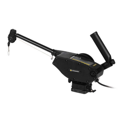
FISHING SPECIALTIES Bowducer User manual

1
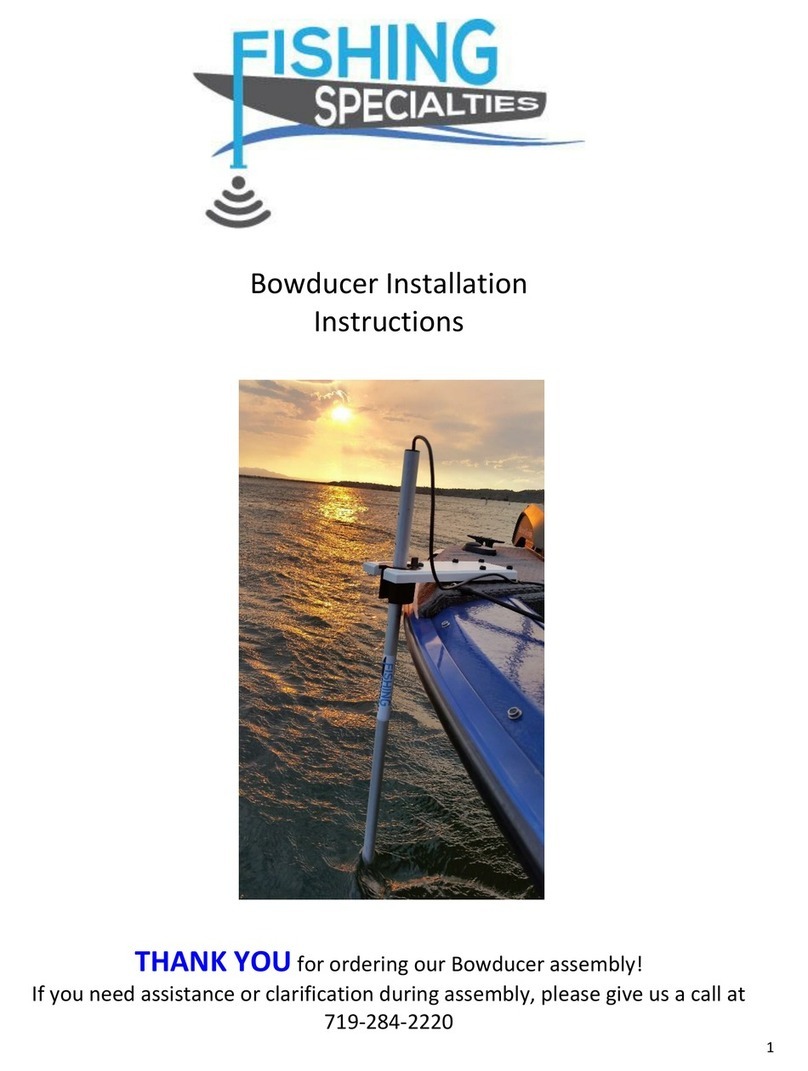
Bowducer Installation
Instructions
THANK YOU for ordering our Bowducer assembly!
If you need assistance or clarification during assembly, please give us a call at
719-640-4948

2
Typical parts in a Bowducer kit include:
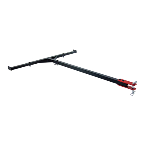
Baseplate Assembly Index Piece Clamping Mount Bracket
Subplate Pedestals Rail Mount bracket
ONLY USE 2 Nylon THUMBSCREWS WITH ANY MOUNTING SYSTEM!
Downrod with cone assembly:
Solid or Telescoping
1” OD, 1.25 OD or 1.5 OD
Assorted Downrod Ends
Transducer to downrod adapter for your transducer
(Style may vary depending on transducer)

3
Installation/Setup of Baseplate:
Special note: Securing Bowducer to sub plates,
pedestals, mounting brackets, etc.
The Bowducer is set up to utilize a 4 hole pattern with the
thumbscrews. In actual use, this is overkill for the marine board
baseplates (and not quite so handy for aluminum baseplates).
Instead of using all 4 mounting holes, use 2 thumbscrews
diagonally from one another. This lowers the holding strength of
the thumbscrews to be below the strength of the marine board
baseplates. It also allows the user to immediately remount the
baseplate should the thumbscrews break away as intended
(improving usability for both aluminum and marine board
baseplates). The immediate replacement of the baseplate will
keep you fishing until you get back and can deal with the broken
stubs of the thumbscrews.
Mounting System Location
When selecting the baseplate location there are several things to consider:
1. Ensure that the downrod will be over the edge of the boat. Do not place it
directly behind the trolling motor propwash as this may interfere with the
sonar return.
2. After selecting your location outline it with tape or some other temporary
marking. Check to be sure that the baseplate assembly will not cause
interference with stowage of trolling motor or other items. Holding the
baseplate to the boat, place the downrod in the cup and place it into position
to be sure that the downrod clears the edge of the boat.

4
3. Use the baseplate or sub plate as a guide to predrill mounting hole locations.
Predrill holes and secure with the stainless steel screws.
4. Very tall pedestals: >6 inches, should be mounted with nuts and bolts (not
provided) if possible to ensure a strong mounting.
Installation of Baseplate:
1. Pre-assemble the baseplate and mounting system (sub plate, pedestal,
bracket, etc.). Use 2 thumbscrews to hold the parts together. Temporarily
place the downrod into the baseplate cup and hold it in with the top latch.
2. Place the completed assembly on the boat at your desired location.
3. Ensure that the downrod clears the rub rail of the boat and that the downrod
will be in a good location for use.
4. Outline the mounting location for sub plate/pedestals with masking tape.
Utilize the mounting plates as a drill guide (pedestal users see below) and
secure these items to the boat.
Installation of Rail mounts (Tracker/Lund):
Rail mounted Bowducer assemblies use appropriate hardware/plates to secure to
the rail of your boats. Installation is generally very straightforward with the
bracket mounting to the rail and the Baseplate assembly mounting atop the
brackets with nylon thumbscrews. Do NOT replace the nylon thumbscrews with
stainless screws. The nylon is a strain relief point and will prevent damage to your
baseplates.
Pedestals:
Pedestals are available in single location versions or movable versions. It may be
necessary to assemble the pedestal:
1. The top plate has 4 threaded holes for the thumbscrews.
2. Bottom plates have 4 holes close to the corners for mounting to the deck.
3. Assemble the bottom plate to the extrusion and then mount to the deck.
Finally, add the top plate.
4. Users with very tall pedestals > 6 inches, should consider the use of a
through bolt and nut with fender washers mounted under the deck. Use
# 10 stainless steel hardware.
5
Movable pedestals:
Movable pedestals utilize two mounting plates on either side of the boat. The
pedestal/baseplate assembly can thus be used on the most advantageous side of
the boat.
Baseplate accessory parts:
Baseplate Tether Kits
Baseplates with removable sub plates, track and rail mounts, and
pedestal mounts are supplied with a tether. The nylon thumbscrews will
tend to snap when an obstacle is accidentally hit. Baseplates will flip into
the water. The tether will hold it to the boat and prevent you fishing the
baseplate from deep or murky water. One end of the tether cable is
uncrimped so you can decide what length may be best for your boat. To
crimp the ferrule simply slide it on and crimp use your fishing pliers or
flatten the ferrule with a hammer!

6
Rubber Bumpers
15 inch Marine Board baseplates are supplied with small
rubber standoffs as there will likely be some flex in the
baseplate assembly. The rubber standoffs are to protect the
boat gunwale.
Installation of the Transducers onto the Downrod
WHEN ASSEMBLING DOWNROD PARTS, ALWAYS REMOVE ALL SCREWS SO YOU
CAN EASILY LOCATE SCREW HOLES
The downrod comes in several styles. You may have a solid or telescoping version which is
between 36 to 60 inches long. There are also 2 diameters: 1” or 1.25” OD and this is
dependent on the depth finder which was specified on your order. There are also a couple
options which may have been ordered: A second downrod cone or perhaps a handle
assembly.
Downrod types
360 Series downrod
Telescoping Downrod
Solid Downrod
Typical Downrod Ends:
Standard Puck
Humminbird Mega g1
Lowrance LSS,
TotalScan, SS
Garmin
Livescope

7
General Instructions:
1. Place all items (cones, strain relief, handles, etc.) onto the downrod –do not
secure them. This includes the transducer mounting end, the cone, handles,
and spare cone if ordered and the heat shrink strain relief
2. Remove the retaining screw for the downrod cone so it will not interfere with
the cable connector.
3. Feed the cable through the transducer mounting end.
Lowrance users, see special note below:
4. Secure the transducer to the downrod end using the general instructions on
the following pages.
Lowrance: If you have a Lowrance
transducer with the blue or black connector,
it is possible to use it with a 1 inch OD
downrod with a bit of modification. You will
need to sand the nubs of the connectors in
order to get it through the downrod as
shown.

8
Connecting the transducer to the downrod end.
For “conventional”transducers from Humminbird or Lowrance, the Mounting disk
shown is supplied.
“Conventional”are defined as those using the following mounting methods:
Lowrance: U shaped metal bracket
Humminbird, 2 - piece transom mounting assembly
Lowrance, Lowrance HDI, Garmin and Eagle:
Lowrance users need only secure the U-shaped
transom bracket to the appropriate holes and connect
the transducer to the metal bracket as recommended
by the manufacturer.
Lowrance Livesight:
The Livesight transducer is only designed for side pole
mount. A bottom bumper is provided to ensure the
transducer cable will not be harmed due to accidental
bottom contact.

9
Humminbird:
Humminbird users need to modify the lower
transom mount plate by drilling out the little tab
shown in the photo to the right
This tab allows for the proper span to the
mounting hole
If the tab is not on the Humminbird backing
plate, you will need to create your own
mounting holes to secure the plate to the disk.
To secure the transducer it will be necessary to follow the steps shown on the next page.
Similar assembly for all transducers using this Humminbird transom mounting kit.
1. Secure ½ in long screw
lightly so plate swivels.
2. Swivel and secure the
hinged piece. Adjust
cable length and
position into cable slot.
3. Turn into position,
tighten screw and
snap closed.
4. Insert second screw ¾
in long
5. Tighten the screw
6. Secure transducer to
its assembly.
Humminbird XHS & XTM 9 HDSI series
1. Lock washers are included to be inserted between the tabs of the transducer and the
tab on the mounting puck (only need to use if transducer remains loose after tightening
the bolt).
2. Transducer should be mounted so its body is under the mounting puck and downrod.
3. Mount the assembly to the downrod.

10
Humminbird Mega Series
1. Run the cable through the downrod
2. Ensure the cable feeds through the cable slot in the disk.
3. Secure the center four mounting screws of transducer to the bottom of the disk with the
supplied screws. Disk is setup for gen 2 and gen 3 mega transducers.
4. Mount the disk assembly to the downrod.
Garmin GT2x, 4x, 5x, Series Transducers:
1. Run the transducer cable through the plate and the disk.
2. Mount the transducer directly to the plate so that the cable at
the top of the transducer runs straight into the disk hole. Use
only the forward 4 mounting screws.
3. Mount the assembly to the downrod.
Garmin Livescope (We STRONGLY suggest bottom of Downrod
mounting to keep transducer vertical and stable when moving through
the water)
1. Run the cable through the disk,
downrod, and handle if supplied.
2. Install Garmin Transom bracket to the
disk and ensure that the bracket is
forward (away from the wire channel)
to allow for as much clearance near the
wire channel as possible. Note: leave a
bit less of a wire loop than shown in the
photo.
3. Mount the metal transducer bracket to
the Livescope and mount that
bracket/transducer assembly to the
transom bracket on the disk. Dress the
cable to allow it to move above the disk
when in down view without causing
excessive bending of the strain relief.
4. Align the transducer and tighten the
bolts. Ensure that the hinge bolts are
“friction” tight to allow the transducer

11
to be moved from FORWARD view to DOWN view –but does easily rotate on the hinge
bolts.
5. If mounting dual transducers, mount the Livescope to the side and the GT series to the
bottom of the downrod using the transom mount assembly as the Livescope photo
shows on the previous page.
6. See handle assemblies information (on last page) for further relevant information.
Garmin Perspective Mounting System:
If you have purchased the add on kit for Perspective view for the Livescope system, the
following bracket is included allow the user to move the transducer between the three view
modes:
Step 1
Install the ball onto the transducer, install
tightly and use the internal tooth lockwasher
between the ball stud and the transducer.
Step 2
Ensure there is about 9.5 inches of cable from the edge of the
mounting disk to the transducer
Step 3
Install the disk end ball to the downrod end using the screws provided.
The RAM logo should be centered over the wire channel.
Step 4
Connect the center arm to the two balls.

12
Perspective mount Hints:
•To allow easier alignment of the transducer with the handle while in perspective view
use index marks on the downrod disk.
•Always try to center the transducer under the downrod to minimize the potential
rotational effect of moving water on the downrod.
•Marine Board baseplates may see additional stress due to the added water resistance of
the perspective bracket. Test carefully to ensure that undue stress is not placed on the
baseplate when moving the boat faster than 3mph.
Lowrance LSS, TotalScan and Structure Scan & 3in1
1. Remove the disk from the plate.
2. Run the cable through the disk and the downrod (make sure cones are on the downrod
as well as the strain relief ring and handle if purchased).
3. Reattach the plate to the disk puck –there is an alignment mark for proper mounting.
Do not attempt to mount the transducer yet. Dress the cable so it is short but can still
be routed through the channel and up the downrod.
4. Secure the transducer to the plate. Make sure that the transducer cable is tight to the
assembly, so it does not catch underwater obstacles.
5. Finally secure the finished assembly to the downrod.
Index Piece (do not use with SI Livesight or Livescope):
The index piece is the cutout portion of the cup (the slot). If you
mount it on the cone (on the downrod), then the downrod can
only go into the cup in one way - thus providing a means of
indexing the downrod to have it aligned to the boat - no matter
how the base is mounted to the boat.
If you are using Down Imaging transducer, you may want the
index to be mounted to the cone/downrod. With the downrod
in the baseplate, simply align the transducer with the boat and then screw the index piece into
the cone. Then you can only deploy the downrod in the proper direction.
If you are using side imaging, then I suggest not using the index piece as it is very handy to be
able to turn the transducer to look for schools of crappie or other structures. In this case,
with the downrod in the baseplate, align the transducer with the boat. Then on the top drill a
small divot (1/4 in drill) in the top of the cone, and a corresponding divot in the top of the cup
(do this from inside the boat so you can see them) and then fill the divot with a bit of white
paint. Then when the dots are aligned, the transducer is in line with the boat. And, if you are
scanning, you will know the transducer direction based on the direction of the dot.

13
SPECIAL ACCESSORIES
Strain Relief Ring:
To protect the cable exiting from the
downrod, we supply a strain relief ring.
Install as shown in the photo. Be sure to
run the cable with the ring installed on
the downrod to prevent cable damage.
Pound the ring onto the downrod as
necessary to fully seat the ring. –it is not
seated in the photo to the right.
Note: Install handles first as the ring is slightly larger than the handle and will not
allow it to pass.
Extra Downrod Cone
IMPORTANT: Place cone on the downrod prior to running cables through the
downrod
The Extra Downrod cone is generally mounted near the bottom of the downrod.
Due to different weights of transducers, we leave it to the user to determine a
proper location. Install the cone so that the downrod is bottom heavy or
balanced. Remove the screw, locate the cone, drill 1/8 in hole thru the downrod,
reinstall the screw. Note: DO NOT use the baseplate for high speed stowage of
the downrod. Stow the downrod safely inside the boat.
Handle Assemblies
Handle assemblies slip over the downrod and are held in place with a set screw.
Install the Handle prior to installing the strain relief ring. You will need to drill a
1/8 inch dia hole to securely set the handle on the downrod.
✓The existing holes on the downrod are not drilled for the
handle!!
✓Typically for Livesight/Livescope, the handle should point in
the same line as the transducer is facing.

14
Warranty
This Limited Warranty covers any defects in material or workmanship under normal
use during the Warranty Period.
During the Warranty Period, Fishing Specialties will repair or replace, at no charge,
products or parts of our product that prove defective under normal use due to bad
material or workmanship.
What will we do to correct problems?
Fishing Specialties will either repair or replace the Product(s) at no charge.
How long does the coverage last?
The Warranty Period for products purchased from Fishing Specialties is 30 days from
the date of purchase.
What does this limited warranty not cover?
This Limited Warranty does not cover any problem that is caused by impact, improper
mounting, or other damage due to external forces.
QUESTIONS:
CALL 719-640-4948 for
Assistance
US Patents applied for on several products in this manual.
Bowducer trademark and all other trademarks retained by Fishing Specialties
Other manuals for Bowducer
2
Table of contents
Other FISHING SPECIALTIES Fishing Equipment manuals