FISNAR F1300N.2 User manual

F1300N.2 Rotary Table Operating Manual
© 2022 Fisnar - 2 - F1300N.2 Rev 01
Table of Contents
Machine Overview 3
Product Safety Statement 4
Specifications 6
Accessories 6
External Controls 7
•Front
7
•Back
10
HMI Controls 14
•Production Screen
14
•Test Screen
18
•Machine Settings Screen
20
Machine Setup 24
Z-Axis Drive Cylinder Setup 26
Dispense Setup 28
Operation Modes 31
•Standard Mode
31
•Pulse Mode
34
•Index Mode
37
Warning Messages 40
•Emergency Stop
40
•Door Open
41
•Reset Machine
42
•Home Machine
43
•Alarm In
44
•Machine Not In Start Position
45
•Cycle Count Limit
46
External Dispenser Actuation 47
EXT. Connector 48
Safety Connector 49
Internal Safety Relay 50
I/O Connector 51
•Schematic
51
•Output Signal Logic
52
•Input Signal Logic
52
•Output Signal Definition
53
•Input Signal Definition
54
•I/O Timing Diagram
54
Spare Part List 55
Machine Drawings 57
Maintenance & Troubleshooting 60

F1300N.2 Rotary Table Operating Manual
© 2022 Fisnar - 3 - F1300N.2 Rev 01
OVERVIEW
FIG. 1: Model F1300N.2 Rotary Table
The F1300N.2 rotary table provides an efficient method of dispensing a circular pattern on
areas that are difficult to access. The tilting Z-axis allows for controlled rotary dispensing at a
fixed angle.
Used for dispensing adhesives, silicones, greases and lubricants
, the F1300N is fully
adjustable in rotation speed, circle diameter, and dispensing time. Dispense from barrels,
cartridges, or valves mounted on the Z-axis.
The Z-axis tilt is easily adjusted to dispense either on a vertical wall within a cylindrical part
or an outside wall. The system is fully programmable to control dispense delay, degree of
rotation, and wait period before cycling.
Three Operation Modes
Standard mode – For dispensing a continuous arc or circle diameter
Pulse mode – For dispensing multiples arcs over a defined circle diameter
Index mode – For dispensing in multiple fixed positions within a arc or circle diameter
Nine programmable memory slots
Adjustable fluid output pressure (0-100psi) for setting and controlling dispense pressure inside fluid
syringe barrel or cartridge. Alternatively used for actuating connected pneumatic dispense valve.
Touch screen LCD display for easy setup and operation
Fully programmable for accurate dispense results
7 channel I/O circuit for external control
Password-protected operator lock-out mode
Industry standard push-in fitting ensure easy system installation and integration into workplace
environments

F1300N.2 Rotary Table Operating Manual
© 2022 Fisnar - 4 - F1300N.2 Rev 01
General Precautions
Do not operate the machine in excess of its maximum ratings / settings.
Make sure the machine is connected to a properly grounded power source.
Make sure that the input air supply is clean and dry. A 5 micron air filter/regulator
(item number 560567) is supplied and recommended to use, so as to ensure the
input air supply is clean and dry.
If Cyanoacrylates adhesives or other moisture sensitive fluids are being used,
an inline coalescing filter (item number 560779C) must be installed to maintain
dispensing system performance.
The fluid being dispensed may be toxic and / or hazardous. Refer to the Material
Safety Data Sheet for proper handling and safety precautions.
Do not smoke or use near an open flame when flammable materials are being
dispensed.
Do not expose the machine directly to sunlight.
Avoid cleaning the machine with aggressive solvents – neutral detergents are
preferred.
Do not touch any moving parts while the rotary table is running.
Loading and unloading of parts must be done when the rotary table is not
moving.
Changing of tooling must be done with the power source disconnected.
EU & UK Safety Requirement
To meet the conformity requirements of the European Community (CE) Machinery
Safety Directive (2006/42/EC) or UK (UKCA) Machinery (Safety) Regulations 2008 this
machine must be placed in an appropriate safety enclosure prior to production use.
F1300N.2 Malfunction
If the machine malfunctions, shut down the machine immediately. This can be
done by either pushing the power switch at the back of the unit
into the off
position or disconnecting the power cord.
Isolate pneumatic air supply to the controller.
Identify the cause of machine malfunction and fix accordingly before switching
back on.
SAFETY

F1300N.2 Rotary Table Operating Manual
© 2022 Fisnar - 5 - F1300N.2 Rev 01
Inappropriate Use
If the machine is used in a way other than described in this manual, it may cause damage
to self or property.
Do not use any components with the machine other than Fisnar authorized
components.
Do not use incompatible materials.
Do not make any modifications to the machine.
All repairs are to be done using Fisnar specified spare parts.
Do not operate the machine in excess of its maximum ratings / settings.
Do not drop or spill foreign objects or material such as screws or liquids into
the rotary table.
Do not operate the machine where electrical noise is present.
Fire Prevention
Refer to the following instructions to avoid any fire or explosion.
Assess your surroundings and the location of the nearest fire extinguisher and
Emergency Exit.
Do not smoke or use near an open flame when flammable materials are being
dispensed.
Immediately disconnect power if any sparking or smoke appears.
Do not expose the machine directly to sunlight.
Maintenance
The F1300N.2 is generally a maintenance free machine. However, to ensure smooth
operation please follow the below instructions.
Only use non-woven cleaners on the machine.
Periodically inspect pneumatic and fluid tubing for signs of fatigue and replace
as necessary
Ensure that compressed air supply to the machine is clean and moisture free.
Periodically check electrical connections and pneumatic fittings are secure.
SAFETY

F1300N.2 Rotary Table Operating Manual
© 2022 Fisnar - 6 - F1300N.2 Rev 01
ACCESSORIES
Item
Description
Quantity
A23EMOT-EA10681V240
Power Adaptor (Input: 100–240 VAC / Output: 24 VDC)
1
5601888
Foot Pedal Switch
1
0603-25400002
30/55cc Barrel Holder Assembly
1
W122000006
8mm OD x 6mm ID Polyurethane Tubing – 10FT
1
W124000081
Straight 6mm OD Push Connector x 1/4" NPT Male
1
A09WP-1705-1-W24
Aux. Dispenser Cable Assy. – 2 metres
1
A10FBMH-6FR
Safety Connector Socket
1
1705-15910002
Internal Safety Relay Wiring Kit
1
W124000120
6mm OD Push to Connect Air Plug
3
W124000185
Push In Fitting 6mm Stem OD X 4mm Tube OD
1
W124000194
Push In Fitting 8mm Stem OD X 6mm Tube OD
1
A10D-TYPE9MHP2-9CASE
9 Pin D-Sub EXT. Connector Socket
1
A10D-TYPE9MHP2-SHORT
9 Pin D-Sub EXT. Shorted Connector Socket
1
A10D-SUB15FR-15CASER
15 Pin D-Sub I/O Connector Socket 1
SPECIFICATIONS
Dimensions (W x D x H): 13.8” x 19” x 22.6” (350 x 482 x 574 mm)
Weight: 24.3 lbs (11 kg)
Input AC to Power
Supply:
100 – 240 VAC, 50 / 60 Hz
Output DC from Power
Supply:
24 VDC – 1 Amp
Rotation Speed: 0 - 60rpm
Work Load: 2 kg (4.4 lb)
Tool Load: 10 kg (22 lb)
Working Area (Diameter): 300mm (12”)
Vertical Travel 100mm (4”)
Air Input: 70 - 100 psi (5 - 7 bar) max
Air Output: 1 – 100 psi (0.07 – 7 bar)
Standards:
CE Approved, UKCA Approved, EMC Compliant,
RoHS Compliant

F1300N.2 Rotary Table Operating Manual
© 2022 Fisnar - 7 - F1300N.2 Rev 01
EXTERNAL CONTROLS
FIG. 2: External Controls Overview - Front
Item Illustration Item Illustration Item Illustration
1 Purge Button 4 Reset Button 7 HMI Display
2 Vacuum Control Knob 5 Start Button 8 Air Pressure Regulator
3 Emergency Stop Button 6 Air Pressure Gauge 9 Start Button
1
2
3
4
9
7
5
6
8
F1300N.2 Rotary Table Operating Manual
© 2022 Fisnar - 8 - F1300N.2 Rev 01
1. Purge Button
Press the purge button to manually dispense fluid material from the
syringe barrel or cartridge.
Or, if using a pneumatic dispense valve, press the purge button to
manually actuate the dispense valve.
2. Suck Back
Control
This feature is only needed if dispensing a low viscosity fluid directly from
a syringe barrel (I.E. syringe barrel adapter a
ssembly is connected
directly to the “Dispense Air Out” port (Fig.4.9
) on the back of the
machine).
It will keep a negative air pressure in the syringe barrel other than when
carrying out the “Rotation Delay” and “Dispense
Angle” phase of the
program cycle, to prevent low viscosity fluids dripping from the dispense
tip in between program cycles.
3. Emergency
Stop
Press the emergency stop button to immediately stop the machine and
cease a program cycle.
4. Reset Button
If the emergency stop button is pressed, it will be necessary to press the
reset button after releasing the emergency stop button before the
machine can be actuated again.
5. Start Button
Press both start buttons (5) and (9) simultaneously to actuate the machine
and begin the program cycle.
6. Dispense
Pressure Gauge
Shows the amount of pressure being used to pressurize the fluid material
in the syringe barrel or cartridge. Or, if using a pneumatic dispense valve,
then this will show the amount of pressure being used to actuate the valve
during the program cycle.
The pressure gauge value is set and controlled by the pressure regulator
(8).
The set pressure is fed out of the back of the machine from the “Dispense
Air Out” port (FIG.4.9) only during the “Rotation Delay” and “Dispense
Angle” phase of the program cycle. Or when the “Purge” button (1) is
pressed.

F1300N.2 Rotary Table Operating Manual
© 2022 Fisnar - 9 - F1300N.2 Rev 01
7. HMI Display
The HMI display is used to,
- Enter the parameters of the program cycle.
- Manually actuate individual components of the machine.
- Adjust machine settings.
For fu
ll information on the HMI Display functions please refer to “HMI
Controls” section.
8. Pressure
Regulator
Adjusts and sets the amount of pressure being used to pressurize the
fluid material in the syringe barrel or cartridge. Or, if using a pneumatic
dispense valve, then this will set the amount of pressure being used to
actuate the valve during the program cycle.
To reach the desired pressure, turn the knob counterclockwise to a point
below the required pressure, and then turn the knob clockwise to reach
the required pressure.
The regulator can be locked into position by tightening the jam nut behind
the knob against the fitting on the front panel of the machine.
9. Start Button
Press both start buttons (5) and (9) simultaneously to actuate the machine
and begin the program cycle.

F1300N.2 Rotary Table Operating Manual
© 2022 Fisnar - 10 - F1300N.2 Rev 01
EXTERNAL CONTROLS
FIG. 3: External Controls Overview - Back
Item Illustration Item Illustration Item Illustration
1 On / Off Switch 8 Cylinder Out Port 15 Sensor Connector
2 Fuse 9 Dispense Air Out Port 16
Foot Switch
Connector
3 I/O Connector 10 USB Connector 17 Exhaust Port
4 Ext. Control Connector 11 Power Input Connector 18 Main Air In Port
5 Ground Connection 12 RS232 Connector 19 Main Air Out Port
6 Cylinder In Port 13 Dispenser Connector
7 Spray Air Out Port 14 Safety Connector
1
2
3
4
5
6
7
8
9
14
15
16
13
17
11
10
12
18
19

F1300N.2 Rotary Table Operating Manual
© 2022 Fisnar - 11 - F1300N.2 Rev 01
1. On / Off Switch
Used to switch the machine on or off.
2. Fuse
A 2.5A fuse is located here to protect the internal electrical circuit.
3. I/O Connector
Where the external machine I/O input signals and output signals are
connected.
A courtesy 24V + output is also included on the I/O Connector.
4. Ext. Control
Connector
Used in applications where external start and stop controls will be used
and/or when the machine is placed inside a safety enclosure and
connected to an external safety circuit with an
externally fitted safety relay.
The optional remote operation box (F1300AKIT-EXTBOX or F1300AKIT-
EXTBOX-SR) can be used in the instances described above.
If this connection is not utilized, the shorted EXT. Control plug MUST be
inserted.
5. Ground
connection
A safe and secure machine grounding point; to be used when the power
input adapter is not connected directly to a grounding point.
6. Cylinder In Port
(4mm OD)
The pneumatic tubing labelled “Cylinder In” from the z-axis drive
assembly is connected here.
7.
Spray Air Out
Port
(6mm OD)
If a spray valve is being used on the machine, then the atomizing air port
of the spray valve is connected here.
If this connection is not required for use, it is recommended that a blanking
plug be inserted into this port.
8.
Cylinder Out
Port
(4mm OD)
The pneumatic tubing labelled “Cylinder Out” from the z-axis drive
assembly is connected here.

F1300N.2 Rotary Table Operating Manual
© 2022 Fisnar - 12 - F1300N.2 Rev 01
9.
Dispense Air
Out Port
(6mm OD)
At the start of a dispensing cycle, the regulated compressed air set by the
pressure regulator and displayed on the pressure gauge on the machine
will exit this port.
It is used to pressurize and dispense the fluid material from the connected
syringe barrel or cartridge during the program cycle. Or, if using a
pneumatic dispense valve, then this will actuate the valve
during the
program cycle.
If this connection is not required for use, due to an external dispense
controller being used to control the dispensing of fluid material during
the program cycle via the “Dispenser” connector port (13), it is
recommended that the pressure regulator on the machine be set to 0psi
and a blanking plug be inserted into this port.
10. USB Connector
For internal use only.
11. Power Input
Connector
The power input cable from the external power supply is connected here.
12. RS232
Connector
For internal use only.
13 Dispenser
Connector
If an external dispense controller is being used to operate the dispense
valve/syringe barrel mounted on the Rotary Table, the signal wires that
actuate the dispense controller are to be connected here.
14 Safety
Connector
Used in applications when the machine is placed inside a safety enclosure
and connected to a safety circuit with an internally fitted safety relay.
The electrical wires of the safety light curtain or door switch are connected
here when an internal safety relay (F1300AKIT-SR
sold separately) is
fitted inside the machine.
If this connection is utilized, the shorted EXT. Control plug MUST be
inserted into the EXT. Control connector (4) if it is not being utilized.
15. Sensor
Connector
The electrical connector from the z-axis drive
assembly is connected
here.
16 Foot Switch
Connector
The foot pedal switch is connected here.
F1300N.2 Rotary Table Operating Manual
© 2022 Fisnar - 13 - F1300N.2 Rev 01
17. Exhaust Port
(4mm OD)
At the end of a program cycle, pressurized air that was used to control the
program cycle will be exhausted from this Exhaust Port.
18. Main Air In Port
(8mm OD)
External Compressed air 70-100 psi (5-7 bar) is to be connected here.
To prevent damage to internal pneumatic components of the machine,
make sure that the input air supply is clean and dry. A 5-
micron air
filter/regulator (item number 560567) is recommended to be used, to
ensure the input air supply is clean and dry.
19.
Main Air Out
Port
(6mm OD)
The compressed air pressure supplied into the “Main Air In” port will exit
from this port.
It can be used to connect to an auxiliary pressure regulator and gauge
(560779SK) to allow the safe and constant pressurization of the
connected fluid feed system (e.g. syringe barrel, cartridge, fluid reservoir
etc.) in applications when a dispense valve is connected to the machine.
If this connection is not required for use (e.g., a syringe barrel or cartridge
is being directly dispensed from), then a blanking plug MUST be inserted
into this port.
F1300N.2 Rotary Table Operating Manual
© 2022 Fisnar - 14 - F1300N.2 Rev 01
HMI CONTROLS
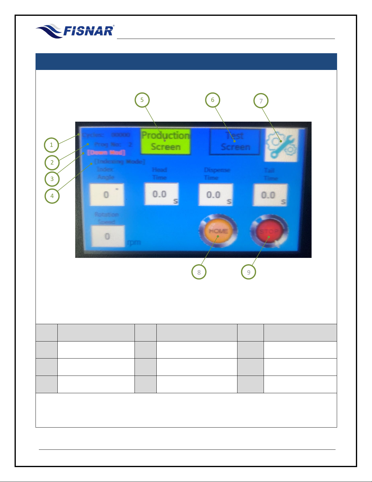
FIG. 4: HMI Controls Overview – Production Screen
Item Illustration Item Illustration Item Illustration
1 Cycle Counter 4 Operation Mode 7 Machine Settings
2 Program Number 5 Production Screen 8 Home Button
3 Static Mode 6 Test Screen 9 Stop Button
1
3
2
4
5
6
7
8
9

F1300N.2 Rotary Table Operating Manual
© 2022 Fisnar - 15 - F1300N.2 Rev 01
1 Cycle Counter
Displays the number of program cycles that have taken place since the
cycle counter was last reset in the Machine Settings screen.
2 Program
Number
Displays the program number the machine is executing.
The program
number is selected in the Machine Settings screen.
3 Static Mode
When the machine has been selected to run in “Static Mode” in the
Machine Settings Screen, the text (Down Mod) will be displayed here.
4 Operation Mode
Displays the operation mode (standard, pulse or index) that the machine
is operating in, which is selected in the Machine Settings screen
5 Production
Screen
Touch this button to display the Production Screen on the HMI.
When the background is highlighted in green color, it confirms that the
Production Screen is being displayed on the HMI.
6 Test Screen
Touch this button to display the Test Screen on the HMI.
Before entering the Test screen a pop-up message will appear requesting
for a password to be entered.
The machine is shipped without a password. Therefore, touch the “Enter”
button to display the Test screen.
If a password has been created by the user of the machine, touch the
empty white box. A pop-up
dialogue window will then automatically
appear allowing the user to type in the password.

F1300N.2 Rotary Table Operating Manual
© 2022 Fisnar - 16 - F1300N.2 Rev 01
Once the password has been entered, touch the “Enter” button on the
dialogue window. The pop-
up dialogue window will then automatically
disappear. The user can then touch the “Enter” button on the original pop-
up message.
When the background is highlighted in green color, it confirms that the
Test Screen is being displayed on the HMI.
7 Machine
Settings
Touch this button to display the Machine Settings Screen on the HMI.
Before entering the machine setup screen a pop-up message will appear
requesting for a password to be entered.
The machine is shipped without a password. Therefore, touch the “Enter”
button to display the Machine Settings screen
If a password has been created by the user of the machine, touch the
empty white box. A pop up dialogue window will then automatically appear
allowing the user to type in the password.

F1300N.2 Rotary Table Operating Manual
© 2022 Fisnar - 17 - F1300N.2 Rev 01
Once the password has been entered touch the “Enter” button on the
dialogue window. The pop-
up dialogue window will then automatically
disappear. The user can then touch the “Enter” button on the original pop-
up message.
8 Home Button
Touch this button to send the motor to its “Home” position.
The “Home” button is only displayed when the production mode has been
set to “Pulse” or “Index” mode.
9 Stop Button
Touch this button to stop the machine in the middle of a program cycle.

F1300N.2 Rotary Table Operating Manual
© 2022 Fisnar - 18 - F1300N.2 Rev 01
HMI CONTROLS
FIG. 5: HMI – Test Screen
Item Illustration Item Illustration Item Illustration
1 Glue Light 4 Cylinder Down Light 7 Motor Button
2 Motor Light 5 Glue Button 8 Home Light
3 Cylinder Up Light 6 Cylinder Button 9 Spray Button
3
1
2
4
7
9
6
5
8

F1300N.2 Rotary Table Operating Manual
© 2022 Fisnar - 19 - F1300N.2 Rev 01
1 Glue Light
When the “Glue” button is in the “ON” position, the Glue Light will light up
green. When the light is green in color the dispense solenoid is active and
the machine is sending the signal to dispense fluid
material from the
syringe barrel/cartridge or actuate the connected dispense valve.
2 Motor Light
When the “Motor” button is in the “ON” position, the Motor Light will light
up green. When the light is green in color the motor on the machine will
be rotating at the speed (rpm) defined in the “Rotation Speed” value on
the production screen.
3 Cylinder Up
Light
When the “Cylinder” button is in the “OFF” position, the Cylinder UP light
will light up green. When the light is green in color it confirms the Z-Axis
drive cylinder is in the “UP” position.
4 Cylinder Down
Light
When the “Cylinder” button is in the “ON” position, the Cylinder Down light
will light up green. When the light is green in color it confirms the Z-Axis
drive cylinder is in the “DOWN” position.
5 Glue Button
This button is used to actuate the dispense
solenoid in the machine.
When in the “ON” position the dispense solenoid is actuated to dispense
fluid material from the syringe barrel/cartridge or actuate the connected
dispense valve.
6 Cylinder Button
This button is used to actuate the Z-Axis drive cylinder on the machine.
When in the “ON” position the Z-Axis cylinder will move to the “DOWN”
position. When in the “OFF” position the Z-Axis cylinder will move to the
“UP” position.
7 Motor Button
This button is used to actuate the motor on the machine. When in the
“ON” position the motor will continuously rotate at the speed (rpm) defined
in the “Rotation Speed” value on the production screen.
8 Motor Home
Light
When the Motor is in its “HOME” position, the Motor Light will light up
green.
9 Spray Button
This button is used to actuate the atomizing air solenoid in the machine.
When in the “ON” position the atomizing air solenoid is actuated to supply
compressed air to the atomizing air port of the connected spray valve.

F1300N.2 Rotary Table Operating Manual
© 2022 Fisnar - 20 - F1300N.2 Rev 01
HMI CONTROLS
FIG. 6: HMI - Machine Settings
Item Illustration Item Illustration Item Illustration
1 E-Stop Condition 8 Change Test Password 15 Cycle Count Limit
2 Firmware Version 9 Change Setup Password 16 Current Cycle Count
3 Total ON Time 10 Operation Mode 17 Reset Count
4 Total Cycles 11 Static Mode 18 Screen Lock
5 Motor Acc. Time 12 Spray Mode 19 Back
6 Motor Rotation 13 Language
7 Auto Cycle Delay 14 Program Select
1
4
9
11
12
10
2
3
5
6
7
8
13
14
15
16
19
17
18
Table of contents
Other FISNAR Laboratory Equipment manuals


Popular Laboratory Equipment manuals by other brands

Sony
Sony FilmStation UP-DF750 Setup and user's manual

Drucker Diagnostics
Drucker Diagnostics Horizon 6 FA Service manual

Elster Instromet
Elster Instromet enCore FC1 manual

Haag-Streit
Haag-Streit LI 900 Instructions for use

Linkam Scientific Instruments
Linkam Scientific Instruments FDCS196 user guide

BD
BD CARV II Installation and user guide


Thermo Scientific
Thermo Scientific EASYpure 1164 Series Operation manual and parts list

Gilson
Gilson PIPETMAN Classic P2 user guide

Purelogic
Purelogic R Series user manual

INTELLICYT
INTELLICYT iQue SCREENER Hardware manual

Omni International
Omni International Omni Mixer owner's manual

MRC
MRC MHK 1-6D Operation manual