FISNAR F1300N User manual

F1300N
Rotary Table Operating Manual
Rev A, February 2018
F1300N
ROTARY TABLE
OPERATING MANUAL

F1300N
Operating Manual
Rev A, February 2018
2
THIS PAGE INTENTIONALLY LEFT BLANK

F1300N
Operating Manual
Rev A, February 2018
3
Table of Contents
SECTION 1: Introduction 5
1. Safety Precautions 6
2. Package contents 7
3. Connector and switch location 9
3.1. Front View 9
3.2. Back View 10
SECTION 2: Setup 11
1. Unpacking the Rotary Table 12
2. Removing the Rotary Table 12
3. Setup 13
3.1. Drive Cylinder Setup 15
SECTION 3: Teaching Overview 16
1. Teaching Overview 17
2. Rotary Table Menu Summary 18
2.1. Production Screen 18
2.2. Test Screen 20
2.3. Setup Screen 22
SECTION 4: Programming Example 24
1. Programming examples 25
1.1. Glue Timings 25
1.2. Motor Timings 26
1.3. Cylinder Timings 26
1.4. Example Program 27
2. Optimizing Dispense Cycle 29
2.1. Dispense Pressure 29
2.2. Rotation Speed 29
2.3. Dispense Angle 29
2.4. Tail Angle 29
2.5. Rotation Delay 29
2.6. Dispense Delay 29
3. Changing the Program Number 30
SECTION 5: Error Messages and Specification 32
1. Error Messages 33
1.1. Door Error 33
1.2. Emergency 33
1.3. I/O Alarm 33
2. I/O Specifications 34
2.1. I/O Pin Assignment 34
2.2. I/O System Specification 35
2.3. Ext. Control Pin Assignments 36
3. System Specification 37
4. Machine Dimensions 38
4.1. Work Table Dimensions 39

F1300N
Operating Manual
Rev A, February 2018
4
SECTION 6: Maintenance and Periodic Inspection 40
1. Check Cycles and Methods 41
1.1. General Considerations 41
1.2. Check Cycles and Points 41
1.3. Check Methods 41
2. Mechanical Parts List 44

F1300N Rotary Table Operating Manual
Section
2: Setup
Rev A, February 2018
5
SECTION 1:Introduction

F1300N Rotary Table Operating Manual
Section
2: Setup
Rev A, February 2018
6
1 Safety Precautions
1.1 In order to meet the requirements of the European Community (CE) safety
directives, the rotary table must be placed in an enclosure supplied by Fisnar Inc.
distributors. The enclosure will prevent the operator from entering the rotary table work
area and will generate an emergency stop signal if the enclosure’s door switch is opened
while the rotary table is running.
1.2 Make sure the rotary table and accessories are connected to a properly grounded power
source.
1.3 Do not drop or spill foreign objects or material such as screws or liquids into the rotary
table.
1.4 Do not touch any moving parts while the rotary table is running.
1.5 Loading and unloading of parts and material must be done when the rotary table is not
running.
1.6 Changing of fixtures or tooling must be done with the power source disconnected.
1.7 The F1300N Rotary Table should only be operated in an environment of 0 to 40 degrees
centigrade and humidity of 20 to 95 percent with no condensation.
1.8 Do not store or install the rotary table in an area where it is exposed to direct sunlight.
1.9 Do not operate the rotary table where electrical noise is present.
1.10 Only use a neutral detergent for cleaning. Do not use alcohol, benzene or thinner.
F1300N Rotary Table Operating Manual
Section
2: Setup
Rev A, February 2018
7
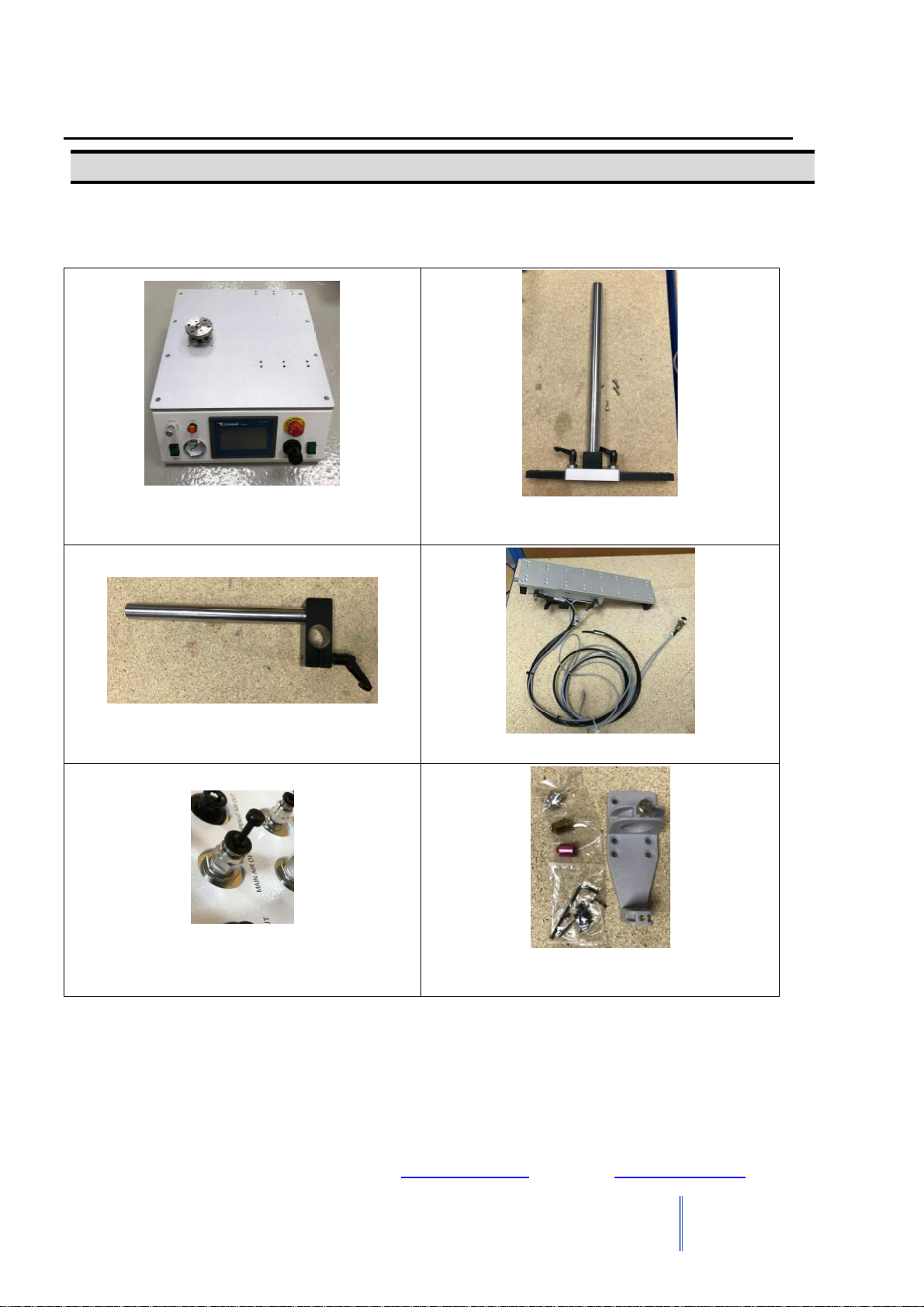
2 Package Contents
In addition to this operating manual, the following items should be included with the rotary
table:
Main Unit Moveable Post Y axis
(mounting screws)
X Axis Post Drive Cylinder Z axis
6mm Mains air out Plug
Barrel Holder
(holder accessories)

F1300N Rotary Table Operating Manual
Section
2: Setup
Rev A, February 2018
8
Mains Air Piping 8mm
Power Cables
Shorted Ext. Connector Plug
Open Ext. Connector Plug
Foot Pedal
I/O Port Connector
F1300N Rotary Table Operating Manual
Section
2: Setup
Rev A, February 2018
9
3 Connector and Switch Locations
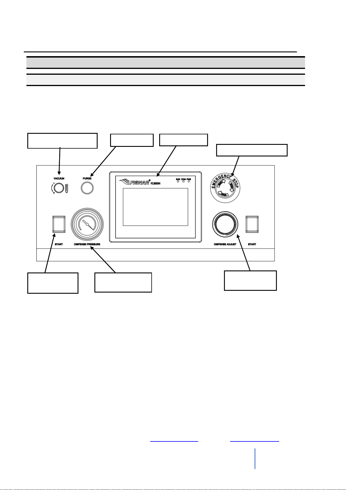
3.1 Front View
Vacuum adjusting knob Purge button
Dispense adjust
knob
Emergency stop button
HMI screen
Dispense pressure
gauge
Start Button

F1300N Rotary Table Operating Manual
Section
2: Setup
Rev A, February 2018
10
3.2 Back View
Sensor
connector
Cylinder in
I/O port
Power
switch
Ext. Control
Fuse
RS232 port
Cylinder out
Serial plate
Dispense air out
Exhaust out port
USB port
Mains air in
Foot switch
24Vdc
power inlet
Mains air out
Spray out

F1300N Rotary Table Operating Manual
Section
2: Setup
Rev A, February 2018
11
SECTION 2:Setup
F1300N Rotary Table Operating Manual
Section
2: Setup
Rev A, February 2018
12
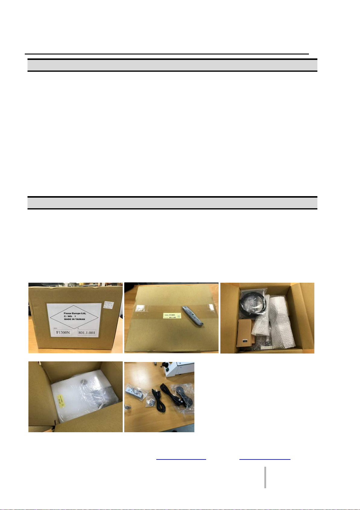
1 Unpacking the Rotary table
•Unpacking the rotary table will require a minimum of two people. Do not attempt to lift the
rotary table without assistance.
•Always lift the rotary table from the base.
•Remove all accessories from the shipping package before attempting to remove the rotary
table.
•Place the rotary table on a stable workbench.
•Do not discard the packing material or the robot’s shipping bracket as these items may be
needed if the rotary table is shipped or moved in the future.
2 Remove
All units are shipped from the factory with Foaming Covers installed. The shipping Foaming
Covers secure the worktable to Y Axis and X/Z head to prevent movement and damage
during shipment.
Remove the shipping Foaming Covers removing the secured tapes.
Keep the Foaming Covers and packages in a safe place for future use.
F1300N Rotary Table Operating Manual
Section
2: Setup
Rev A, February 2018
13
3 Setup
The F1300N Rotary tables are available in many different configurations. The configuration of
each machine and the accessories used with each system will depend on the customer’s
application.
The steps required to setup a system using a 30 cc or 55 cc barrel are listed below.
3.1. If the system is being used in the European Community, the rotary table must be
placed in an enclosure supplied by Fisnar Inc. distributors. The enclosure will prevent
the operator from entering the rotary tables work area and will generate an emergency
stop signal if the enclosure’s door switch is opened while the rotary table is running.
Connect the external start / stop box and door switch or light curtain to the Ext. Control
connector on the main unit. For further information, see Error! Reference source not
found. Ext. Control Connector.
If an enclosure is NOT being used, the enclosure door switch can be bypassed by
connecting the plug labeled SHORTED (included in the rotary table accessories
box) to the Ext. Control Connector.
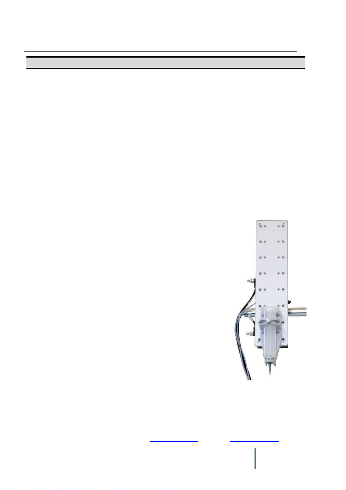
3.2. Standard systems are shipped with a barrel holder, which
must be mounted on the Z head of the rotary table. The
barrel holder will hold a 30 cc or 55 cc barrel on the rotary
tables head. An optional valve / cartridge bracket assembly
may be used as a replacement for the barrel holder if the
application so requires.
3.3. Mount the barrel holder or valve bracket assembly on the Z
axis head as shown, using two screws. The barrel holder
has several sets of mounting holes to allow it to be
mounted at different heights. Choose mounting holes which
give maximum work piece clearance but allow the tip to
reach all areas on the work piece where dispensing is
required.

F1300N Rotary Table Operating Manual
Section
2: Setup
Rev A, February 2018
14
3.4. When the Rotary table base is set on a secure work table, take the X axis mounting
post and fix it to the mounting table top, use the M5 x 25 cap head screws supplied
with the post.
3.5. Mount the secondary Y axis post to the X axis post at an appropriate height for the
application. The post’s height is locked in place using the threaded locking handle and
slotted mounting bracket.
3.6. Mount the air cylinder Z axis moving plate onto the Y axis mounting post, the mounting
bracket will slide on the post into position based on the application specified. The air
cylinder’s Y axis position and dispense angle can be locked in place using the
threaded locking handle. The “cylinder in” must be at the bottom of the drive cylinder or
the Z axis will travel in the wrong direction.
3.7. Connect the pneumatic pipes to the matching labelled tube to tube fittings. I.e. pipe
labelled “cylinder out” to back panel 4mm push connector labelled “cylinder out”.
Connect the cylinder in pipe to the cylinder in 4mm push connector. The Z axis drive
cylinder sensors connector to the back panel 4 pin connector labelled “sensor”
3.8. Connect the extras from the accessary box. Pneumatic plug into mains air out. Shorted
ext. connector to link the emergency stop signal. Mains air in, 6mm air fitting. Connect
the power plug to a 230vac mains power plug.
3.9. Check all connections are secure, and none of the pneumatic connections are leaking
air.
3.10. Tie back all cables and air lines so that they will not interfere with the rotary tables
motion when the rotary table is operating. Be sure that the cables and air lines do not
restrict the motion of the rotary tables, Z axis drive cylinder and of the rotary tables
motor and make sure that they cannot become jammed as the rotary table moves in
the work area.
3.11. The mounting posts can but moved and slid into place and aligned with the area of
dispense of the specified part.
3.12. It is recommended to setup the flow control valves that regulate the drive cylinder
before positioning the dispense tip to the application. This can be done when driving the
cylinder in the “test screen”. Set the flow control to drive the cylinder at a controlled speed
that meets application requirements.
Note that this unit ships with a Shorted External Control Connector. This is not
connected when shipped. Unless this is plugged in, the unit will display an EMG
ERROR (Emergency Stop). Please insert the Shorted Connector.
F1300N Rotary Table Operating Manual
Section
2: Setup
Rev A, February 2018
15
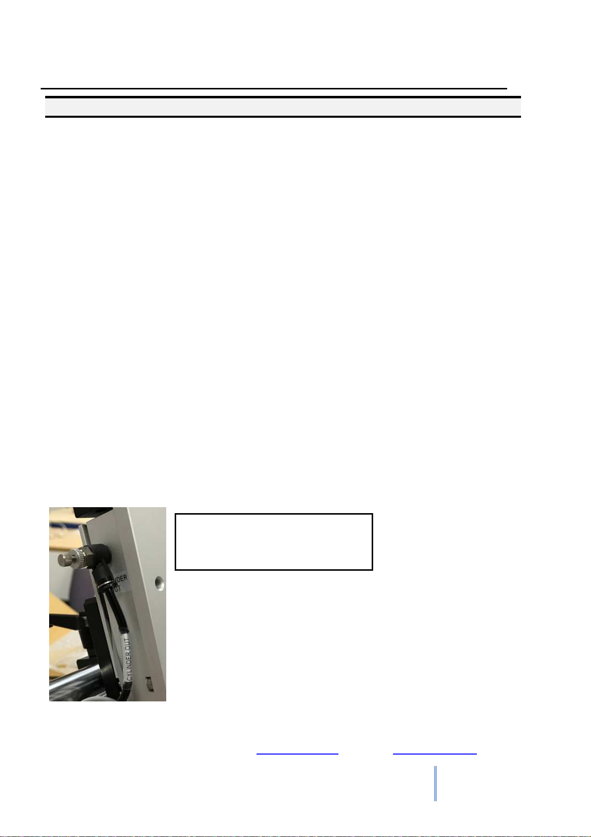
3.1 Drive cyclinder Setup
To correctly set up the drive cylinder for application usage:
After plumbing in the mains air supply to the 8mm fitting on the back of the rotary table,
and the 4mm cylinder in and clyinder out pipes into the correct flow relugator fittings.
Use and dummy program to set up the cylinder movement speeds
Fully close both flow regulators before beginning.
Start the Dummy program to actuate the pneumatics and being to move the drive
cylinder.
Slowly open the “Cylinder In” flow regulator to release the air pressure in the drive
cylinder and begin the movement down towards the dispesne location
When the cylionder is moving at a speed appropriate for the application use the locking
nut to set the flow regulator parameter.
After the Cylinder in flow regulator is set, then repeat the above to set the “Cylinder
Out” flow regulator the same way, by opening until the required speed is set and lock it
in place
The flow regulators are pneumatic dampeners, meaning they act as slow air release air
cushions to control the movement speed of the drive cylinder.
Cylinder out flow regulator,
showing locking nut and adjustable
knob for flow rate.

F1300N Rotary Table Operating Manual
Section 3: Teaching Overview
Rev A, February 2018
16
SECTION 3:Teaching Overview

F1300N Rotary Table Operating Manual
Section 3: Teaching Overview
Rev A, February 2018
17
1 Teaching Overview
A program consists of a series of parameters stored in the main unit memory. Each parameter
is stored in a numbered program memory. The programs consist of motor rotation angle,
speed and control delays.
When the program is executed, the rotary table will actuate the Z axis drive cylinder to travel
to dispense position set mechanically during set up. When the cylinder reaches travel
distance the delay timers start and begin the parameter set dispense sequence.
The rotary table applications are for full circular dispensing applications. Being internal
gaskets or external gaskets on a rounded object. Or an application for a rounded dispense
less than a full circle.
F1300N Rotary Table Operating Manual
Section 3: Teaching Overview
Rev A, February 2018
18
2 Rotary Table Menu Summary
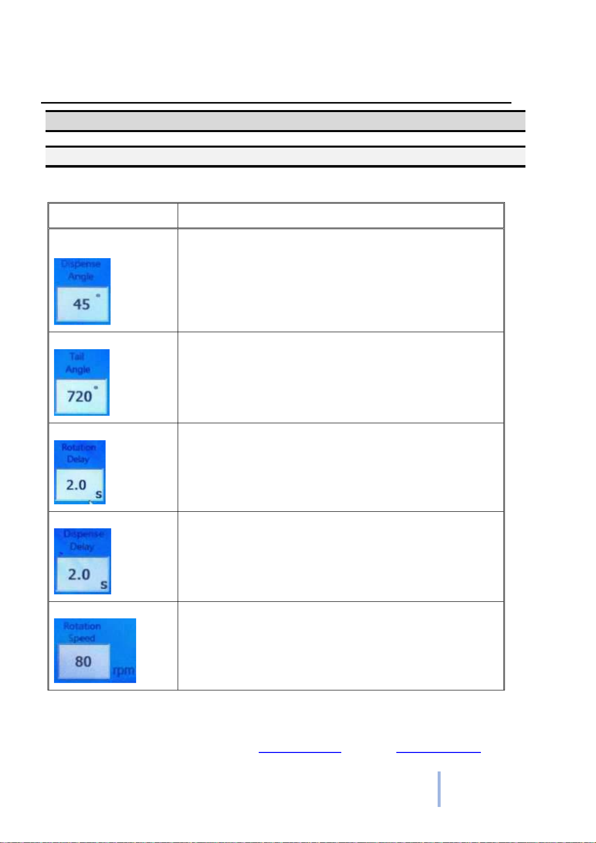
2.1 Production Screen
Below is a list of functions, which are found under the Production Screen:
Function
Description
Dispense Angle
Sets the parameter for the angle of rotation of the motor
during the dispense cycle
Tail Angle
Sets the parameter for the angle of rotation for after the
dispense angle is complete (no material is dispensed on this
angle)
Rotation Delay
This is a time in seconds to create a delay before beginning
the dispense angle rotation. This time starts once the drive
cylinder moves into place.
Dispense Delay
This is a time in seconds to create a delay before the start of
material dispense. This time starts once the drive cylinder
moves into place.
Rotation Speed
This is the speed of motor rotation during the dispense cycle.
Measured in RPM.

F1300N Rotary Table Operating Manual
Section 3: Teaching Overview
Rev A, February 2018
19
Function
Description
setup screen
This button opens the settings menu on the HMI touch
screen. This menu is password protected.
Test Screen
This button opens the Test screen on the HMI touch screen.
This menu is password protected.
F1300N Rotary Table Operating Manual
Section 3: Teaching Overview
Rev A, February 2018
20
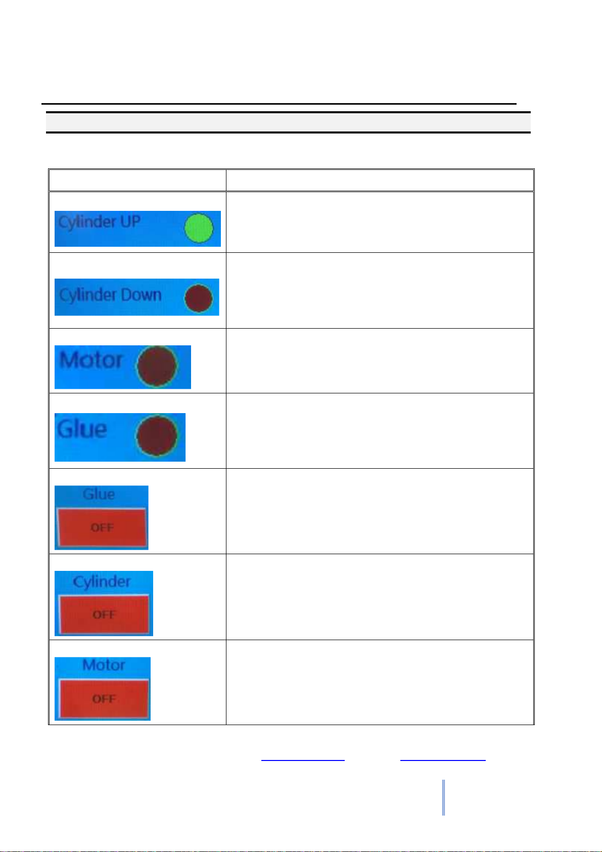
2.2 Test Screen
Below is a list of functions, which are found under the Test Screen:
Function
Description
Cylinder Up
Shows a red or green light to show when this function is
active or in active. When active it shows the drive
cylinder is at the top of its location.And when inactive it
shows the cylinder isn’t at the top of its location.
Cylinder Down
Shows a red or green light to show when this function is
active or in active. When active it shows the drive
cylinder is at the bottom of its location.And when
inactive it shows the cylinder isn’t at the bottom of its
location.
Motor
Shows a red or green light to show when this function is
active or in active. When active it shows the motor is
rotating at the speed set in the production screen. And
when inactive it shows the motor isn’t moving.
Glue
Shows a red or green light to show when this function is
active or in active. When active it shows the dispense
solenoid is active and the rotary table is dispensing fluid.
When inactive the solenoid is close and no fluid is being
dispensed.
Glue On/Off
This button actuates the dispense solenoid in the rotary
table system to test if it is functioning correctly. On,
opens the solenoid to dispense fluid. Off, closes the
solenoid and stops fluid from being dispensed.
Cylinder On/Off
This button actuates the drive cylinder to move from its
top position, to its bottom position. On, drives the
cylinder from its top position to its bottom position. Off,
drives the cylinder from its bottom position to its top
position.
Motor On/Off
This button activates the motor to rotate at the speed set
in the production screen. On, starts the motor rotation.
Off, stops the motor rotation.
Table of contents
Other FISNAR Laboratory Equipment manuals


Popular Laboratory Equipment manuals by other brands

Oxford Instruments
Oxford Instruments ANDOR Sona 4.2B-6 Hardware guide

Helmer Scientific
Helmer Scientific TCR Operation and service manual

Grant
Grant GLS Aqua Plus operating manual

Caiman
Caiman NITEHOG TIR-M50 manual

Metrohm
Metrohm 940 Professional IC Vario ONE/LPG manual

ProteinSimple
ProteinSimple Maurice S user guide


