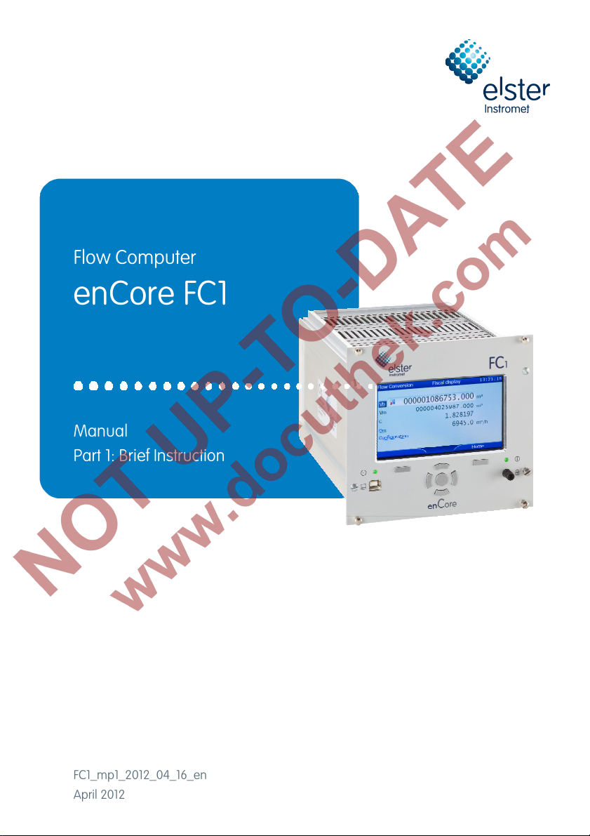
Elster Instromet enCore FC1 User manual

Flow Computer
enCore FC1
Manual
Part 1: Brief Instruction
FC1_mp1_2012_04_16_en
April 2012

Page 2 of 44 Brief Instruction enCore FC1

enCore FC1 Brief Instruction Page 3 of 44
Contents
1About this Technical Documentation 5
2General legal information 7
2.1 Legally Relevant Information at the Device Itself 7
2.2 Additional Static Information 7
2.3 Additional Variable Information 8
3FC1: General Information 9
3.1 enCore and enSuite 9
3.2 FC1: General Device Description 9
3.3 FC1: Hardware 11
3.4 FC1: Software 12
3.4.1 The enCore Software Concept 12
3.4.2 FC1: Legally Relevant Software (for Fiscal Use) 13
3.4.3 FC1: Non-Legally Relevant AFBs (for Non-Fiscal Applications) 13
3.4.4 FC1: AFB Structure for Common Applications 14
4FC1: Operation for Legally Relevant Functionalities 18
4.1 Operating Controls 18
4.1.1 Keys 19
4.1.2 Touch Screen 19
4.1.3 Security Switch 19
4.1.4 LEDs 20
4.1.5 Power LED 20
4.1.6 Information LED 20
4.2 Display and Navigation 21
4.2.1 Display Test 21
4.2.2 Different Types of Device Displays 21
4.2.3 Navigation via Touch Screen 22
4.2.4 Navigation via Keys 23
4.2.5 Indication of Physical Quantities: Symbols 23
4.2.6 How to Get to the Displays Showing Legally Relevant Data 24
4.3 USB Port for PC Connection 31

Page 4 of 44 Brief Instruction enCore FC1
4.4 Parameterization 31
4.5 Software Download 31
5FC1: Legally Relevant Functionalities 33
5.1 Basic System 33
5.2 Gas Quality AFB 34
5.3 Flow Conversion AFB 36
6FC1: Technical Data 39
6.1 General 39
6.2 Inputs 39
6.3 Outputs 40
6.4 Digital communication interfaces 41
7Index 42
8Appendix 44

About this Technical Documentation 1
enCore FC1 Brief Instruction Page 5 of 44
1 About this Technical Documentation
This technical documentation is the first part of the encore FC1 manual.
It briefly describes the legally relevant properties of the enCore FC1 flow
computer. Apart from topics such as General device information and
Technical data, Display and Operation, Basic functionalities and Description
of compulsory AFBs (Application Function Blocks), there is an Appendix
including approval certificates and other legally relevant documents (if
applicable).
Thus, the documentation on hand is not only an introductory summary for all
users but also intended for all interested parties such as approval authorities
and notified bodies.
In the following, the short name ‘FC1’ is mostly used for the term ‘enCore
FC1’.
The first and the second part of the documentation are included in printed
form in the FC1 delivery (first part is the documentation and hand, the
second part is the Instruction Manual (see below).
Please read the first and the second part of the manual carefully
and completely before starting to work with the FC1, especially
prior to installation.
The manufacturer does not assume any liability for damage and
failures caused by disregard of the manual.
The complete FC1 manual comprises the following additional parts:
Part 2 Instruction Manual
The second part describes the installation, commissioning, mainte-
nance, and disposal of the FC1 device.

1 About this Technical Documentation
Page 6 of 44 Brief Instruction enCore FC1
All safety information is contained in the second part of the FC1
manual (Instruction Manual).
The documentation on hand (First part: Brief instruction) does not
include any safety information.
Part 3 Description of the Basic System incl. SFBs
Description of available AFBs
Part 3 is a composition of several documents and consists of a
description of the Basic System including the SFBs (System
Function Blocks, basic functionalities) and additional descriptions of
all AFBs (Application Function Blocks) being available for the FC1
Flow Computer. Part 3 of the documentation is delivered in electronic
form only.
The third part of the manual is intended for all specialized readers
who are interested in AFB functionality details. In particular, these
documentations are necessary for configuring the device parame-
terization according to requirements. The information provided is
completed by the parameter descriptions included in the enSuite
online help (enSuite = PC software supporting enCore devices).

General legal information 2
enCore FC1 Brief Instruction Page 7 of 44
2 General legal information
2.1 Legally Relevant Information at the Device Itself
The device's type plate reveals the most important legal information at first
glance. The type plate may be divided in several parts; its exact appearance
depends on the approval to be applied. Please refer to the Appendix for
official documents, if applicable.
The following table lists the legally relevant information that can be found at
the device itself:
Information Location
CE mark and other legally required
markings (such as Approval number
and Identification of the Notified
Body)
Type plate
Identification of the manufacturer Elster's identification mark, printed
on front panel
Serial number Type plate
Year of manufacture Type plate
Table 1: Legally relevant information at the FC1 front / rear panel
2.2 Additional Static Information
MPE at reference conditions
(including AD conversion) 0.2%
Extreme temperatures of the
environmental class
Ambient temperature range -10 °C
to +55 °C
Battery life time Not applicable (external power
source)

2 General legal information
Page 8 of 44 Brief Instruction enCore FC1
IP class IP20
European standard EN 12405-1
Table 2: Additional static information
2.3 Additional Variable Information
Software version and checksum A software identification display can
be evoked by activating the
button in the device's Home display
(please refer to Chapter 4.2.6).
Base pressure and base
temperature
Upper and lower limits of the
transducers
Parameters for gas meter error
correction curve
Pulse value
Compression algorithm
Gas properties
Apart from the base pressure, all
here mentioned settings are subject
to parameterization.
The base pressure is fixed pb =
1.01325 bar, according to European
standards.
During runtime, all these settings
can be checked at the device's
display (configuration displays,
please refer to Chapter 4.2.6).
Table 3: Additional variable information

FC1: General Information 3
enCore FC1 Brief Instruction Page 9 of 44
3 FC1: General Information
3.1 enCore and enSuite
enCore is the name of an Elster product platform for advanced measure-
ment devices. All enCore devices are based on the same hardware compo-
nents and software concepts.
enSuite is the collective name for all PC software supporting enCore
devices. The enSuite software collection provides tools for configuration,
parameterization, diagnosis, software download and other servicing pur-
poses.
The enCore FC1 device is a flow computer based on the enCore platform.
3.2 FC1: General Device Description
The enCore FC1 flow computer is an electronic conversion device for meas-
uring and calculating the flow of natural gas. Different measurement devices
are to be connected to the flow computer (gas meters, pressure transmitters,
temperature transmitters and, optionally, gas quality measurement devices).
Depending on the type of the individual measurement device, the FC1 pro-
vides different connection and interfacing options:
Device type Connection options
Gas meters
Pulse interface for turbine, rotary or other
pulse generating gas meters
Serial interface for Ultrasonic gas meters
(digital protocol)
Interface for gas meters equipped with an
Encoder index
Pressure transmitters 4..20 mA input
HART protocol interface

3 FC1: General Information
Page 10 of 44 Brief Instruction enCore FC1
Temperature
transmitters
Resistance input
HART protocol interface
Gas quality
measurement devices
Serial interface
TCP/IP interface
Table 4: Connection of measurement devices
Number of streams / number of flow directions
Due to the expandable hardware and software concept, the maximum
number of streams and flow directions is variable. It depends on the amount
of available device resources, the individual hardware settings and the soft-
ware configuration.
European Standards
The FC1 flow computer supports the following European calculation
standards:
Value to be calculated Selectable calculation standards
Compressibility AGA8-92 DC (ISO 12213-2)
SGERG-88 (ISO 12213-3)
AGA-NX19 mod
AGA-NX19 mod BR.KOR.3H
AGA-NX19 GOST
Density,
Relative density
AGA8-92 DC
ISO 6976
Heating values,
Wobbe Indices ISO 6976
Table 5: Supported calculation standards

FC1: General Information 3
enCore FC1 Brief Instruction Page 11 of 44
Parameterization
The FC1 flow computer is configured by using the parameterization software
that is included in the enSuite software collection and runs on a PC or laptop
(Windows).
3.3 FC1: Hardware
The FC1 flow computer consists of a rack-mountable card cage with an
operation panel on the front side.
At the rear side, the compulsory CPU board additionally offers one network
TCP/IP interface and two serial RS232 / RS422 / RS485 interfaces. These
interfaces are typically intended for the connection of gas quality measure-
ment devices or other devices equipped with a protocol interface.
Several different I/O boards can be mounted from the rear side. The FC1
device is available in two housing sizes, i.e. with a mounting width of 1/3 for
up to four process boards or a mounting width of 1/2 for up to seven process
boards. The I/O board configuration is variable; Table 6 shows an overview
of all available I/O boards.
In principle, all board types can be mounted in any slot.
There is a restriction for MSER4 boards only: In case of a device with a
mounting width of 1/3, one MSER4 can be mounted in slot 4. A device with a
mounting width of 1/2 can contain up to two MSER4 boards (in slot 6 and
slot 7).
ExMFE5 * Input board providing 3 NAMUR inputs for status,
LF or HF pulses or Encoder index; 1 analog /
HART input; 1 Pt100 input. All inputs are intrinsi-
cally safe.
Intended for the connection of gas meters (via
pulses or Encoder index), pressure transmitters
(4..20 mA or HART), temperature transmitters
(resistance input or HART).

3 FC1: General Information
Page 12 of 44 Brief Instruction enCore FC1
MFE7 * Input board providing 3 inputs (24 V DC) for status,
LF or HF pulses or Encoder index; 2 analog /
HART inputs; 1 Pt100 input, 1 RS485 serial inter-
face.
Intended for the connection of gas meters (via
pulses or Encoder index), ultrasonic gas meters
(RS485 serial interface), pressure transmitters
(4..20 mA or HART), temperature transmitters
(resistance input or HART).
MSER4 * Communication board providing 4 serial interfaces
(RS232 / RS422 / RS485). Typically intended for
the connection of gas quality measurement
devices.
MFA8 ** Output board providing 4 digital outputs for status,
LF pulses or frequency; 4 analog outputs.
* for legally and non-legally relevant purposes
** for non-legally relevant purposes only, non-interacting regarding the
legally relevant functionalities
Table 6: enCore I/O boards
Please refer to Chapter 6for further technical details.
3.4 FC1: Software
3.4.1 The enCore Software Concept
The device software of each enCore product consists of:
a Basic System, containing several basic functionalities (SFBs)
and
a number of so-called Application Function Blocks (AFBs).

FC1: General Information 3
enCore FC1 Brief Instruction Page 13 of 44
As the Basic System is responsible for all basic functionalities (such as I/O
interface connection, protocol interface connection), it is an integral part of
each device's software.
An AFB is a single application-driven functionality which can be added or
removed by parameterization. In principle, the device can use each AFB
once, twice or more times, depending on the individual requirements. The
AFB configuration is regulated by a credit concept only – each AFB is worth
a certain number of credits, and the number of available credits within an
individual device can be limited.
3.4.2 FC1: Legally Relevant Software (for Fiscal Use)
The Basic System with its basic functionalities is always legally relevant.
There are two types of AFBs that are legally relevant, namely the Gas
Quality AFB and the Flow Conversion AFB:
The Gas Quality AFB calculates the compression factor C, density and
heating values by using pressure, temperature and gas quality measurement
data, taking the selected calculation standards and the base conditions to be
applied into consideration.
The Flow Conversion AFB generates counters for volumes at base and
measurement conditions as well as mass and energy by using the gas meter
measurement data and the results of the Gas Quality AFB. It performs the
gas meter correction and the counter administration due to error handling
and – if applicable – the flow direction switching.
3.4.3 FC1: Non-Legally Relevant AFBs (for Non-Fiscal
Applications)
Additional non-legally relevant AFBs can be added without affecting the
legally relevant software.

3 FC1: General Information
Page 14 of 44 Brief Instruction enCore FC1
Examples:
AFB Function
Post-processing Generation of new event-oriented values derived
from existing values (such as actual values,
differential values, averages, or drag indicators)
Archive Data logging
Modbus Modbus communication for a single Modbus
communication line
Table 7: Examples for non-legally relevant AFBs
3.4.4 FC1: AFB Structure for Common Applications
The device software of a basic FC1 flow computer consists of the Basic
System, one Flow Conversion AFB and one Gas Quality AFB. This configu-
ration implements a typical “one stream, one flow direction” application.
Figure 1: Data flow for a basic “one stream, one flow direction” application

FC1: General Information 3
enCore FC1 Brief Instruction Page 15 of 44
For other applications, i.e. with more than one stream and/or more than one
flow direction, more AFBs of the Flow Conversion and Gas Quality type are
used.
General rules:
One Flow Conversion AFB is necessary for each stream and for each
flow direction.
One Gas Quality AFB is necessary for each C calculation working with
different measurement data (pressure / temperature and/or gas quality)
or based on different calculation rules (as to calculation standards
and/or base conditions).
The Flow Conversion and Gas Quality AFBs working with the same
measurement data are linked via parameterization. The parameterization
supports the grouping of AFBs in user-defined structures. This way, it is easy
to identify which AFBs belong together in both, the parameterization user
interface and the device screen.
Examples of typical applications:
1 stream, 2 flow directions, 1 gas quality measurement
For a flow computer application with one stream and two flow directions (fd 1
and fd 2), there have to be two sets of counters (one for each flow direction)
whereas the pressure, temperature and gas quality measurement has to be
performed only once. This means that two Flow Conversion AFBs and one
Gas Quality AFB are necessary, provided that the same GQ calculation
standards and the same base conditions are to be applied to both flow
directions.

3 FC1: General Information
Page 16 of 44 Brief Instruction enCore FC1
Figure 2: Data flow for 1 stream, 2 flow directions
2 streams
For a flow computer application with two streams, two Flow Conversion
AFBs and two Gas Quality AFBs are necessary.
Figure 3: Data flow for 2 streams, 1 flow direction each

FC1: General Information 3
enCore FC1 Brief Instruction Page 17 of 44
2 streams: the first one with 2 flow directions and 1 gas quality
measurement, the second one with 1 flow direction
Figure 4shows a flow computer application handling two streams, one with
two flow directions (fd 1 and fd 2) and one with one flow direction. In that
case, one block containing two Flow Conversion AFBs and one Gas Quality
AFB and one block containing one Flow Conversion and one Gas Quality
AFB are needed. That sums up to three Flow Conversion AFBs and two Gas
Quality AFBs altogether – provided that for both flow directions of the first
stream the same GQ calculation standard and the same base conditions are
to be applied.
Figure 4: Data flow for 2 streams (dual / single fd)

4 FC1: Operation for Legally Relevant Functionalities
Page 18 of 44 Brief Instruction enCore FC1
4 FC1: Operation for Legally Relevant
Functionalities
4.1 Operating Controls
Figure 5: FC1 operating controls
Navigation keys
Function keys
Touch screen
Security switch (sealable)
Power LED
Status LED
USB port for PC connection

FC1: Operation for Legally Relevant Functionalities 4
enCore FC1 Brief Instruction Page 19 of 44
4.1.1 Keys
There are 2 function keys located directly below the touch screen. Pressing
one of these keys activates the corresponding display button which is indi-
cated directly above.
The navigation buttons (Up, Down, Left, Right, Enter) are intended for navi-
gation within the device software's menu as an alternative to an operation
via the touch screen.
Figure 6: Navigation keys
Up
Down
Left
Right
Enter
4.1.2 Touch Screen
All key operations can alternatively be executed from the touch screen. An
acoustic signal indicates that an operating action has taken place.
4.1.3 Security Switch
The security switch is a sealable rotary switch which is located on the front
panel. It is closed by turning it clockwise as far as it will go.
The security switch is part of the enCore user rights limitation concept. A
closed security switch prevents certain user actions that affect the function of
the device (e.g. parameter modifications or functionalities like the software
download).
Note: For devices used in legal metrology, official documents may exist
prescribing how the security switch has to be sealed. Please refer to the
Appendix, if applicable.

4 FC1: Operation for Legally Relevant Functionalities
Page 20 of 44 Brief Instruction enCore FC1
4.1.4 LEDs
There are two multicolor LEDs on the front panel, the Power LED and the
Information LED.
4.1.5 Power LED
LED status Meaning
Off Power off
Red Power off, USB connection detected
Green Power on, no USB connection
Orange Power on, USB connection active
Table 8: Power LED
4.1.6 Information LED
The Information LED indicates whether an error affecting the legally relevant
functionalities is pending or has been pending.
LED status Meaning
Off Power off
Green, flashing A green flashing light appears during the start-up phase
after a power failure.
Green, perma-
nently illuminated
The device's legally relevant functionalities are running
error-free.
Red, flashing An error is pending that affects the legally relevant
functionalities.
Other manuals for enCore FC1
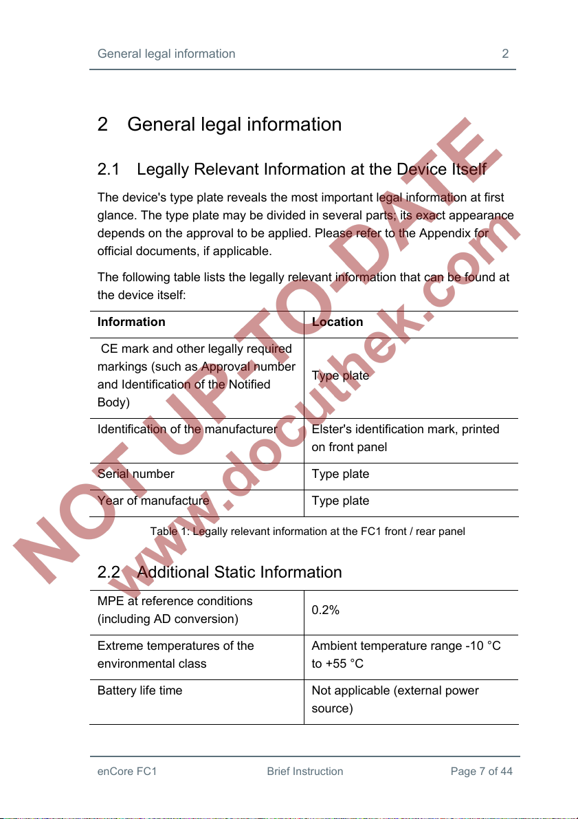
1
Table of contents
Other Elster Instromet Laboratory Equipment manuals
Popular Laboratory Equipment manuals by other brands

Fisher Scientific
Fisher Scientific Fisherbrand GT2 instruction manual

Fritsch
Fritsch PULVERISETTE 7 classic line operating instructions

ASL INTERCOM
ASL INTERCOM 130 instruction manual

Oxford Optronix
Oxford Optronix HypoxyLab user manual

IKA
IKA C-MAG HS 10 Service manual

VWR
VWR PerfectBlue Maxi S instruction manual