FISNAR F7000N User manual
F7000N Tip Alignment Device Guide Rev. A –May 20th 2015
Fisnar Inc. | 19C Chapin Rd. Ste. 307, Pine Brook, NJ 07058 | T: (973) 646-5044 | [email protected] |
www.fisnar.com
- Page 1 -
F7000N Tip Alignment Device
Guide

F7000N Tip Alignment Device Guide Rev. A –May 20th 2015
Fisnar Inc. | 19C Chapin Rd. Ste. 307, Pine Brook, NJ 07058 | T: (973) 646-5044 | [email protected] |
www.fisnar.com
- Page 2 -
Contents
i. Tip Alignment Device Overview........................................................................................................ 3
ii. Hardware .......................................................................................................................................... 4
iii. Hardware Installation ....................................................................................................................... 5
iv. Setting the Device ............................................................................................................................. 5
v. Device Movement............................................................................................................................. 8
vi. Tip Changing Examples ..................................................................................................................... 8
vii. Technical Drawing of Tip Alignment Device ................................................................................. 9
viii. Connecting an External Device ...................................................................................................10
ix. F7000N Input/ Output Schematic................................................................................................... 12

F7000N Tip Alignment Device Guide Rev. A –May 20th 2015
Fisnar Inc. | 19C Chapin Rd. Ste. 307, Pine Brook, NJ 07058 | T: (973) 646-5044 | [email protected] |
www.fisnar.com
- Page 3 -
i. Tip Alignment Device Overview
The Tip Alignment Device use sensors to check position of the dispensing tip and will correct position if
the tip is changed or damaged. The device is connected to the user Input port on the back of the robot.
The Sequence of Tip Alignment is
1) Set Base Tip Position (first time only)
2) Run Setup Tip Alignment.
3) Create dispensing program.
4) Run program
5) After tip change, run XYZ Search to correct for any offsets.
The Tip Alignment Device only affects the current program. So if a new program is created, Tip Search
Position and Tip Alignment for the new program must be completed.
Minimum Robot Software Required for Tip Alignment Device: Version 26.5

F7000N Tip Alignment Device Guide Rev. A –May 20th 2015
Fisnar Inc. | 19C Chapin Rd. Ste. 307, Pine Brook, NJ 07058 | T: (973) 646-5044 | [email protected] |
www.fisnar.com
- Page 4 -
ii. Hardware
Included in each Tip Alignment Device Package is the device itself and the work plate that it is attached
to.

F7000N Tip Alignment Device Guide Rev. A –May 20th 2015
Fisnar Inc. | 19C Chapin Rd. Ste. 307, Pine Brook, NJ 07058 | T: (973) 646-5044 | [email protected] |
www.fisnar.com
- Page 5 -
iii. Hardware Installation
Shown above is the device connection to the robot work plate as well as a way to secure it to the robot
side. During installation, please try and correctly level the device as any offsets can affect the tip
correcting functionality.
iv. Setting the Device
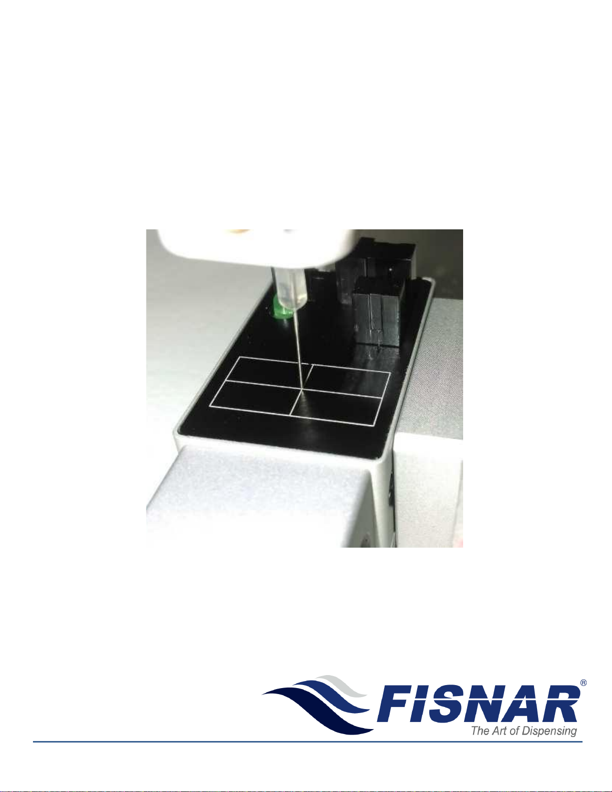
Step 1. Jog the dispensing tip to the middle of square
position as shown by the picture to the right.
In step 1, please try to move the tip as close to the surface
of the center as possible so that it could save searching
time.
Step 2:
Enter Setup Menu→Select “Tip Search Position” Function
on page 3/4.

F7000N Tip Alignment Device Guide Rev. A –May 20th 2015
Fisnar Inc. | 19C Chapin Rd. Ste. 307, Pine Brook, NJ 07058 | T: (973) 646-5044 | [email protected] |
www.fisnar.com
- Page 6 -
Step 3:
Enter Tip Search Position.
(1) Press [F1] on the Teach Pendant to record the
dispensing tips current position.
(2) Length input will adjust how far down in the Z
direction the tip will search from the starting position.
Step 4:
Enter Setup Menu→Select Tip Search on page 4/4.
Step 5:
Enter Tip Search Function and choose F2 Setup. The
device will run and will know the initial tip position and
could correct for offsets based on this location.
<F1> Base: Move to Tip Search Position previously set.
<F2> Setup: To get initial value of tip position.
<F3> XYZ Search: To adjust the offset value of Tip.
The Tip Alignment Device is now setup and can correct the position if dispensing tip is changed or
damaged.
If the dispensing tip is changed, follow the steps below to correct for any XYZ offsets.
Correcting for XYZ Offsets in Teach Mode
Step 1:
Enter Tip Search on page 4/4 of Setup Menu and select F3.
XYZ Search. The tip will now search for its initial position and
correct for any offsets. This is the Teach Mode correction
option. To correct for offsets in Run Mode, proceed to step 3
below.
Step 2:
If Tip has offset, the screen will show the X, Y, Z offset values.
Click enter on each offset to accept its value. To offset the
program, select 1 and click enter again.
Run the program to ensure the offsets have been correctly
adjusted for.
F7000N Tip Alignment Device Guide Rev. A –May 20th 2015
Fisnar Inc. | 19C Chapin Rd. Ste. 307, Pine Brook, NJ 07058 | T: (973) 646-5044 | [email protected] |
www.fisnar.com
- Page 7 -
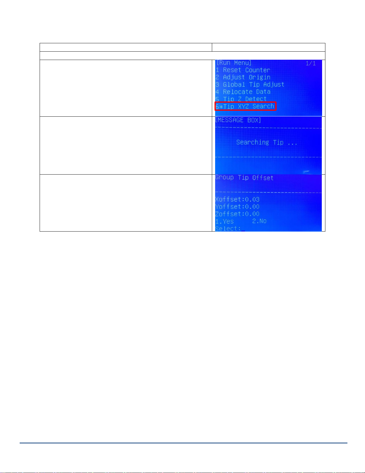
Correcting for XYZ Offsets in Run Mode
Step 1:
Change the robot to Run Mode using the switch on the front
panel.
Press <F1> to enter Run Menu and choose Tip XYZ Search.
Step 2:
After choosing Tip XYZ Search, Tip will search on Tip Detect
Position.
Step 3:
If Tip has offset, the screen will show the X, Y, Z offset values.
Click enters on each offset to accept its value. To offset the
program, select 1 and click enter again.
Run the program to ensure the offsets have been correctly
adjusted for.

F7000N Tip Alignment Device Guide Rev. A –May 20th 2015
Fisnar Inc. | 19C Chapin Rd. Ste. 307, Pine Brook, NJ 07058 | T: (973) 646-5044 | [email protected] |
www.fisnar.com
- Page 8 -
v. Device Movement
As the tip moves, it is triggering the sensors and its position is being recorded. If the Tip Alignment fails,
make sure the tip is triggering the sensor as it moves in the X, Y and Z direction. This can be easily done
by adjusting the starting position of the tip in the Tip Search Position command as well as the Length it is
searching in the Z direction.
The above images show the movements and positions the Tip Alignment Device makes when it is
correcting for offsets. Home Position, Tip Starting Position and the Tip Search Pattern are all shown
above.
vi. Tip Changing Examples
1). Program 0 and program 1 are using an 18 Gauge tip with the same Setup Position.
If the tip is changed to another 18 Gauge tip,
To use program 0 => load program 0 =>run XYZ Search.
To use program 1 => load program 1 =>run XYZ Search.
Home Position
Tip Starting Position
Tip Search Pattern

F7000N Tip Alignment Device Guide Rev. A –May 20th 2015
Fisnar Inc. | 19C Chapin Rd. Ste. 307, Pine Brook, NJ 07058 | T: (973) 646-5044 | [email protected] |
www.fisnar.com
- Page 9 -
2). Program 0 and program 1 are using an 18 Gauge tip with the same Setup Position.
If the tip is changed to a 20 Gauge tip, as long as the tip is the same length,
To use program 0 => load program 0 => run XYZ Search.
To use program 1 => load program 1 => run XYZ Search.
3). Program 0 and program 1 are using an 18 Gauge tip with the same Setup Position.
If the tip is changed to a longer 16 Gauge tip, Base Tip Position as well as Setup alignment must be
redone to change the searching characteristics. Once Setup is completed, run XYZ Search.
To use program 0 => load program 0 => New Base Tip Position => Setup Tip Initial Position =>run XYZ
Search.
To use program 0 => load program 0 => New Base Tip Position => Setup Tip Initial Position =>run XYZ
Search.
vii. Technical Drawing of Tip Alignment Device

F7000N Tip Alignment Device Guide Rev. A –May 20th 2015
Fisnar Inc. | 19C Chapin Rd. Ste. 307, Pine Brook, NJ 07058 | T: (973) 646-5044 | [email protected] |
www.fisnar.com
- Page 10 -
viii. Connecting an External Device
To allow the Tip Alignment Tool to be better integrated into more complex systems, an external
device such as a Push Button can be utilized to trigger the Alignment device without the use of
the standard Teach Pendant. This feature is only available in robot RUN mode.
Step 1:
Return to the Setup Menu and
select Tip Search Ext. Trigger on
page 4/4.
Step 2:
Set Enable (1/0) to 1. This will allow
an input to be used to trigger the
Tip Alignment Device.
Enter the corresponding Input Pin
that will be used.

F7000N Tip Alignment Device Guide Rev. A –May 20th 2015
Fisnar Inc. | 19C Chapin Rd. Ste. 307, Pine Brook, NJ 07058 | T: (973) 646-5044 | [email protected] |
www.fisnar.com
- Page 11 -
Please follow the information below to properly connect an external device to the Tip Alignment Device.
Example. Connect the external device to pin 26 (Input 1) and any open pin from 34-50 (COM). In the Tip Search Ext.
Trigger function make sure the correct input is entered. Change the robot into RUN Mode and once the input signal
is closed, the Tip Alignment Device will run XYZ Search and correct for any offsets.
Connector Pin Locations
Notes:
To close an input signal, short the circuit between the input pin (26 –33) and a COM /
ground pin (ANY pin # 34 - pin 50).
Input signals are powered by the robot internal power supply: 5 volts, maximum 2.5 mA
When the input pin (pin 26 –33) is connected to a COM pin (pin #34 - #50), the value of
the input is 0.
For additional information please refer to the F7000N Robot User Manual.
Connector
Pin
Description
26
IN # 1
27
IN # 2
28
IN # 3
29
IN # 4
30
IN # 5
31
IN # 6
32
IN # 7
33
IN # 8
34
COM
35
COM
36
COM
37
COM
38
COM
39
COM
40
COM
41
COM
42
COM
43
COM
44
COM
45
COM
46
COM
47
COM
48
COM
49
COM
50
COM
F7000N Tip Alignment Device Guide Rev. A –May 20th 2015
Fisnar Inc. | 19C Chapin Rd. Ste. 307, Pine Brook, NJ 07058 | T: (973) 646-5044 | [email protected] |
www.fisnar.com
- Page 12 -
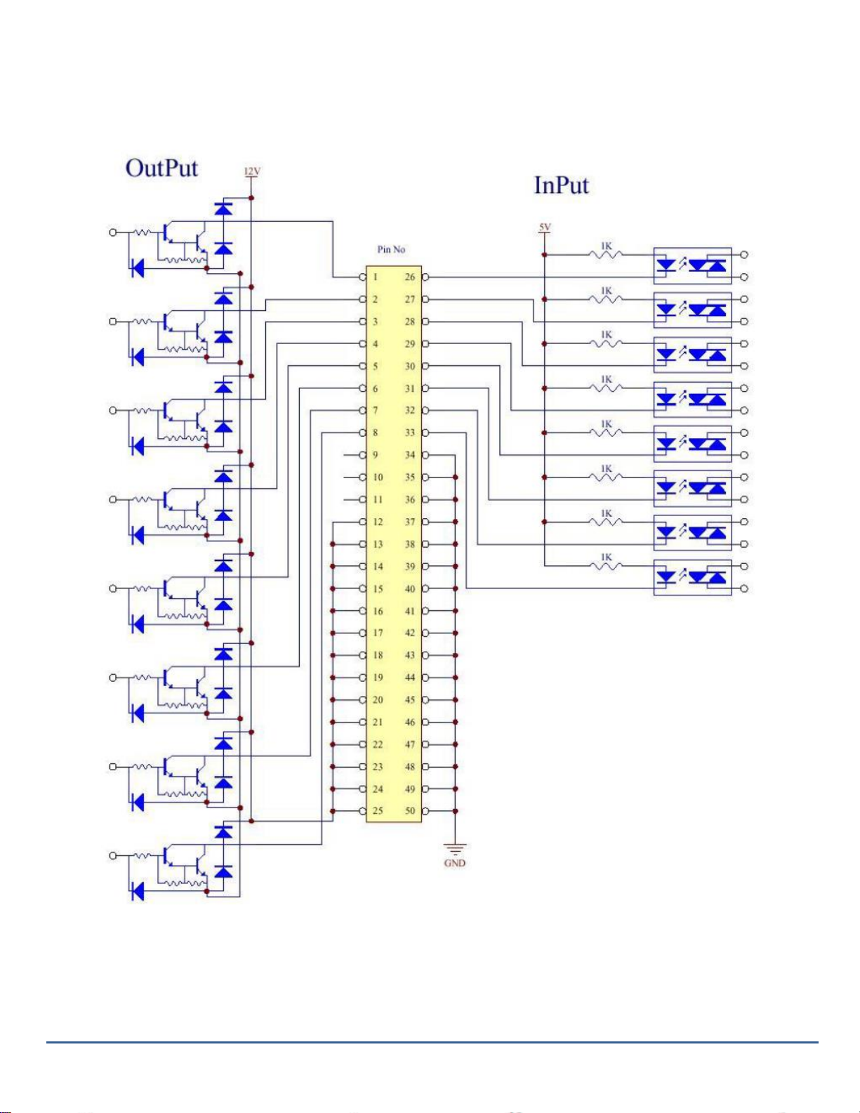
ix. F7000N Input/ Output Schematic

F7000N Tip Alignment Device Guide Rev. A –May 20th 2015
Fisnar Inc. | 19C Chapin Rd. Ste. 307, Pine Brook, NJ 07058 | T: (973) 646-5044 | [email protected] |
www.fisnar.com
- Page 13 -
Table of contents
Other FISNAR Laboratory Equipment manuals


Popular Laboratory Equipment manuals by other brands


Star Lab
Star Lab Ergo One user manual

J.P. SELECTA
J.P. SELECTA FRIGITERM TFT-10 instruction manual

Gema
Gema OptiFlow IG06-BN Operating instructions and spare parts list

PerkinElmer
PerkinElmer Lambda 650 Hardware guide

PerkinElmer
PerkinElmer RamanFlex 400 Series Getting started guide

Amanngirrbach
Amanngirrbach ceramill liquid instruction manual