Fitel S218R-Plus User manual
FTS-B553-04
S218R-Plus Hot Stripper
Operating Instructions
•Please read entire manual prior to usage.
•Please keep this manual with the S218R-Plus.
Issue 03
Apr. 2019

FTS-B553-04
1
Contents
Contents ...........................................................................................................1
1Safety Instructions.....................................................................................2
2Components..............................................................................................5
2.1 Standard Components............................................................................5
2.2 Optional Components.............................................................................5
3Specifications............................................................................................5
4Unit Description.........................................................................................6
5Preparation ...............................................................................................7
5.1 Battery setting ........................................................................................7
5.2 Charging the Battery...............................................................................8
6Operating Instruction.................................................................................9
7Adjusting temperature...............................................................................9
8Setting power save mode..........................................................................9
9Recharging Battery .................................................................................10
10 Confirming Battery Remaining.................................................................10
11 Maintenance ...........................................................................................10
12 Replacing the blade ................................................................................10
12.1 Replacing the lower blade ....................................................................10
12.2 Replacing the upper blade....................................................................11
12.3 Upper blade adjustment........................................................................11
13 Others.....................................................................................................12
13.1 The usage of the Adjusters (spacer).....................................................12
13.2 Mounting the Stand (Optional parts) for the unit ...................................13
13.3 Single fiber adapter (Optional parts) installation. ..................................13
13.4 Storage for the S944 Battery Pack .......................................................14
14 Holding period for spare parts.................................................................14
15 Contacts..................................................................................................14
FTS-B553-04
2
1 Safety Instructions
This manual contains the complete operating and maintenance instructions for S218R Hot Stripper.
Please review this manual carefully before operating the S218R Hot Stripper.
The following safety instructions must be observed whenever this product is operated, serviced or
repaired. Failure to comply with any of these instructions or with any precaution or warning contained
in this manual is in direct violation of the standards of the design, the manufacture and the intended
use of the instrument. FURUKAWA ELECTRIC CO., LTD. assumes no liability for the customer’s
failure to comply with these requirements.
Safety Instructions
!
WARNING
Failure to comply with any of the instructions, which
are indicated by this symbol, may cause serious
injury or death.
!
CAUTION
Failure to comply with any of the instructions, which
are indicated by this symbol, may cause serious
injury or damage to the AC/DC Power Supply and
other materials.
Please contact FURUKAWA ELECTRIC CO., LTD. with any questions relating to the description of
this manual.
In no case will FURUKAWA ELECTRIC CO., LTD. be liable to the buyer, for any consequential or
indirect damage which is caused by product failure, malfunction, or any other problem.
!
WARNING
•Avoid soaking the AC/DC Power Supply, Battery or Battery recharger with water. Doing so
may cause fire, electrical shock or malfunction.
•Do not use inappropriate input voltage. Doing so may cause fire, electrical shock or
malfunction.
•Do not use any AC/DC Power Supply other than the attached one. Do not use the attached
AC/DC Power Supply as a power supply other than for the S218R-Plus. Doing so may cause
fire or malfunction.
•Avoid direct skin contact with the heating portion. This may cause burn or injury.
•If smoke, abnormal sounds, extra high temperature or strange smells are observed, power off
and disconnect the S218R-Plus from the power source and contact FURUKAWA ELECTRIC
CO., LTD. or your local representative. Continuing to operate under these conditions may
cause fire, electrical shock or malfunction.
•Do not use a damaged power cord with the inner cable is exposed or is severed. Doing so
may cause fire or electrical shock.
•If water spilled into the S218R-Plus, power off and disconnect the S218R-Plus from AC outlet.
Continuing to operate under these conditions may cause fire or electrical shock.
•If the S218R-Plus is dropped and damaged, disconnect the power source. Continuing to
operate under these conditions may cause fire or electrical shock.
•Do not operate the S218R-Plus at temperatures less than 0ºC or above 40ºC. Do not expose
to high temperatures. Doing so may cause fire, electrical shock or malfunction.
•Do not short-circuit the DC plug. Doing so may cause fire or electrical shock or malfunction.
FTS-B553-04
3
The S944 Battery is made of Li-ion battery cells. Refer to following safety instructions on handling and
operating the Battery safety.
!
WARNING
•Do not dispose the Battery in fire, or leave the Battery near a high-temperature object. Doing
so may cause fire or explosion.
•Do not short-circuit the recharging connector or the output terminal for splicer. Doing so may
cause fire by generation of heat.
•Charge the S944 Battery by the S218R/S218R-Plus. If charging by other equipment that is
not suitable for charging S944, it may cause fire.
•Avoid soaking the Battery with water. Doing so may cause fire or electrical shock.
•Do not disassemble the Battery. Avoid damage by dropping or heavy shock. Doing so may
cause fire or electrical shock. If inner cells rupture and electrolytic solution leaks outside, it
may cause inflammation to your skin or eyes.
•Disposal of used Battery must be carried out according to disposal established by Law. For
instructions, contact Furukawa electric Co., Ltd. or your local representative.
!
CAUTION
•Do not disassemble the S218R-Plus. The S218R-Plus contains no user serviceable parts.
Warranty on this product will be invalidated if any part of the S218R-Plus is disassembled.
•Do not use in a humid, dirty or vibration site. Doing so may cause fire, electrical shock or
malfunction.
•Do not place the S218R-Plus on an unstable or inclined surface. The S218R-Plus may fall and
cause injury.
•Disconnect all cords when using DC cord and moving the S218R-Plus. Doing so may damage
the cords which may cause fire or electrical shock.
•Do not place the S218R-Plus around any heating instrument. Doing so may damage the cords
which may cause fire or electrical shock.
•Do not connect or disconnect cord with wet hands. Doing so may cause fire or electrical
shock.
•Do not pull the cord to disconnect. Doing so may damage the cord which may cause fire or
electrical shock. Hold the plug portion and disconnect the cord.
•Do not put heavy items on the cords. Doing so may damage the cords which may cause fire
or electrical shock.
•Use only the cord attached to the S218R-Plus. Connecting inappropriate cords or extending
the cords may cause them to heat up abnormally and may cause fire.
•Do not modify the cords and do not over-bend, over-twist or over-stretch the cords. Doing so
may cause fire or electrical shock.
•Ensure that the cords are disconnected, when storing the S218R-Plus.
FTS-B553-04
4
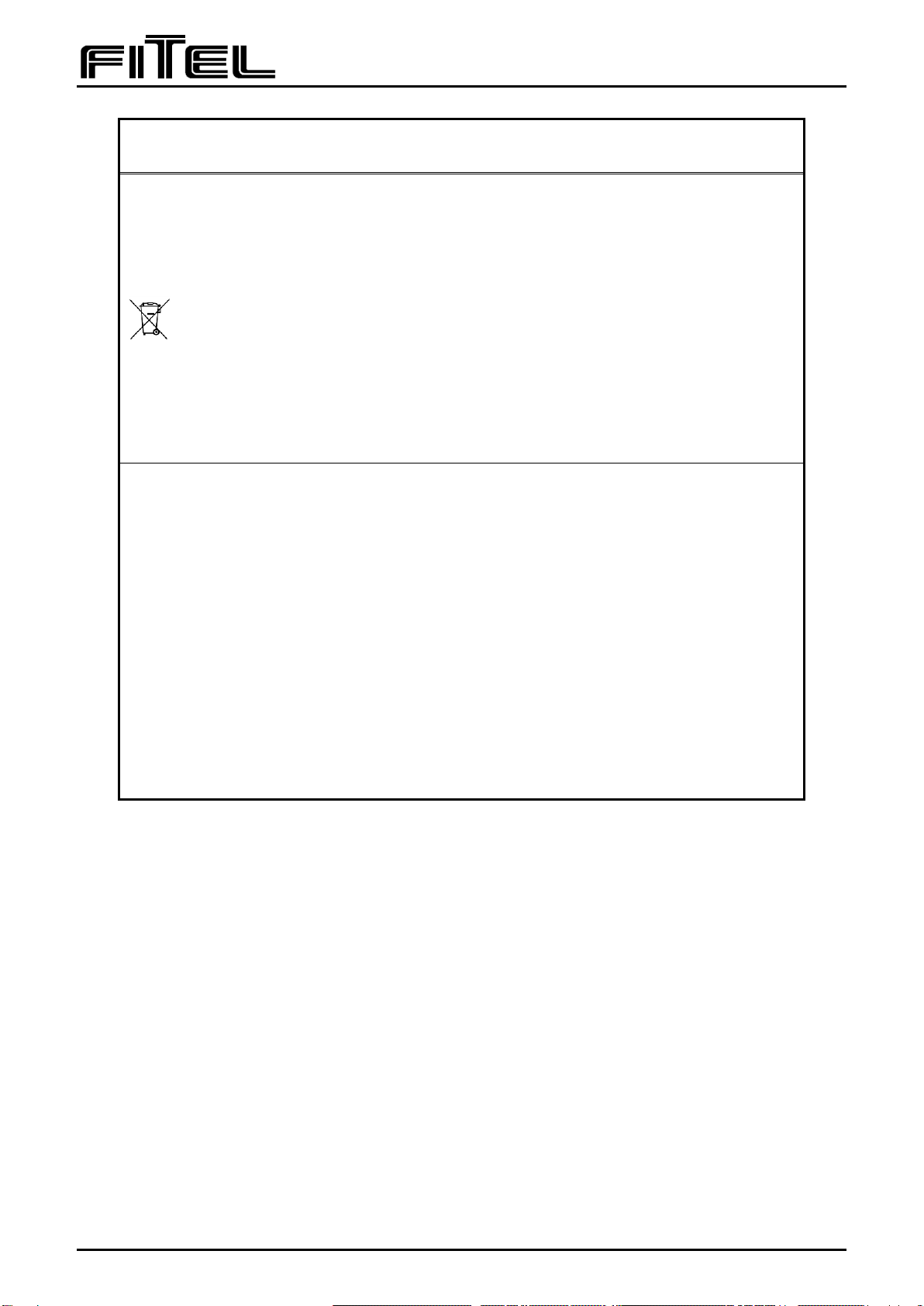
Notes
This symbol mark is for EU countries only.
This symbol mark is according to the directive 2006/66/EC Article 20 Information for
end-users and Annex II.
This symbol means that batteries and accumulators, at their end-of-life, should be
disposed of separately from your household waste.
If a chemical symbol is printed beneath the symbol shown above, this chemical symbol
means that the
battery or accumulator contains a heavy metal at a certain concentration. This will be
indicated as follows:
Hg: mercury (0.0005%), Cd: cadmium (0.002%), Pb: lead (0.004%)
In the European Union there are separate collection systems for used batteries and
accumulators.
Please, dispose of batteries and accumulators correctly at your local community waste
collection/recycling centre.
Please, help us to conserve the environment we live in!
This device complies with part 15 of the FCC Rules. Operation is subject to the following
two conditions: (1) This device may not cause harmful interference, and (2) this device
must accept any interference received, including interference that may cause undesired
operation.
FCC CAUTION
Changes or modifications not expressly approved by the party responsible for compliance
could void the user’s authority to operate the equipment.
Note: This equipment has been tested and found to comply with the limits for a Class A
digital device, pursuant to Part 15 of the FCC Rules. These limits are designed to provide
reasonable protection against harmful interference when the equipment is operated in a
commercial environment. This equipment generates, uses, and can radiate radio frequency
energy and, if not installed and used in accordance with the instruction manual, may cause
harmful interference to radio communications. Operation of this equipment in a residential
area is likely to cause harmful interference in which case the user will be required to
correct the interference at his own expense.
This Class A digital apparatus complies with CAN ICES-003(A).
Cet appareil numérique de la classe A est conforme à la norme NMB-003(A)..

FTS-B553-04
5
2 Components
2.1Standard Components
Name
Code
Quantity
Remarks
Main Body
S218R-Plus
1
Battery Pack
S944
1
Li-Ion Rechargeable Battery
AC adaptor
S952
1
AC→DC Converter
Allen key set
S218X-07
1
Tools used for replacing blade
Case
S218X-04
1
Protection Case
Strap
1
Cleaning brush
1
Operating Manual
FTS-B553
1
2.2Optional Components
Name
Code
Quantity
Remarks
Single Fiber Adapter
S218X-03
1
The adapter for stripping single fiber
Blade for S218R-Plus
S218X-88
1(set)
See manual in 11 Replacing the blade
Battery Pack
S944
1
Li-Ion Rechargeable Battery
AC adaptor
S952
1
AC→DC Converter
Adjuster
S218X-22
1
It is used for adjusting removing length of
fiber.
Stand
S218X-23
1
Unit frame supporter.
3 Specifications
Description
Minimum
Typical
Maximum
units
Fiber cladding diameter
125
µm
Single fiber coating range
250
400
µm
Applicable fiber ribbons
2
12
-
Ribbon thickness
250
400
µm
Rollable ribbon thickness
200
250
µm
Electrical
Input terminals from AC supply
85
264
VAC
Power consumption
10
Watt
Dimension (W x D x H)
Main body (S218R-01)
S944 Battery Pack
S952 AC adaptor
48 x 125 x 41
39.5 x 55.8 x 20.9
62 x 99 x 26
mm
mm
mm
Weight
Main body (S218R-01)
S944 Battery Pack
S952 AC adaptor
180
80
270
g
g
g
Environmental
Operating temperature
Storage temperature
Humidity (Non condensing)
0
-40
40
60
90
°C
°C
%RH

FTS-B553-04
6
4 Unit Description
Holder clamp
Heater lid
Heater
Fiber ribbon
Min. line
(25mm)
Max. line
(35mm)
(LED)
Fiber holder
Holder clamp lid
Power Switch
Temperature Trimmer
Mode switch
Battery cover
Screw for the Battery cover
Rear side
Charge status LED
DC jack
Front side
Indication lamp
Blade
Top side (with the Fiber holder)
Bottom side (without Battery cover)
Contact
Blade
-
+
Polarity of DC jack

FTS-B553-04
7
5 Preparation
5.1Battery setting
Mount the S944 Battery Pack into the S218R before using it.
1)Loosen the screw of the Battery cover by using
an Phillips-head screwdriver.
2)Remove the Battery cover by pushing it to the
direction as shown at right.
3)Set the Battery Pack in the Main body to fit both
contacts.
4)Put the Battery cover back to the unit, then tighten
the screw.
Contact
S944 Battery pack
1)
2)
Remove the Battery cover
Contact
Set S944 Battery Pack
Screw the Battery Cover

FTS-B553-04
8
5.2Charging the Battery
1)Let S944 battery Pack be remained in S218R Hot Stripper.
2)Connect S952 AC adaptor to AC power outlet (85-264V, 50/60Hz) using AC power cord.
3)Connect S218R Main body to S952 AC adaptor using DC plug cable.
4)The orange charge LED will be illuminated and the battery will start to be charged.
It will take approximately 150 minutes to fully charge the Battery. When the Battery is fully charged,
the Charge status LED will turn off automatically.
S944 battery can be charged while the unit is being used, however, in such case, charging rate or
speed is tenth of the rate when the unit power is off.
If charging errors occur, the orange Charge status LED will be blinking.
!
Warning
If errors occur during charging process, please swiftly remove the
S944 Battery Pack from Main body, then contact your local
representative for assistant.
It is dangerous to continuously operate the unit under these
conditions, which may cause fire or electrical shock.
Charge status LED
DC jack
Front side
DC plug connected to S218R
FTS-B553-04
9
6 Operating Instruction
1) Connect to a power source with appropriate wiring (DC/DC converter only) and press power switch.
The Indication Lamp (LED) lights red to indicate power is being supplied to the S218R-Plus.
2) The LED color will change from red to green approximately 15 seconds later to indicate that the
S218R-Pkus is warmed up and ready to use.
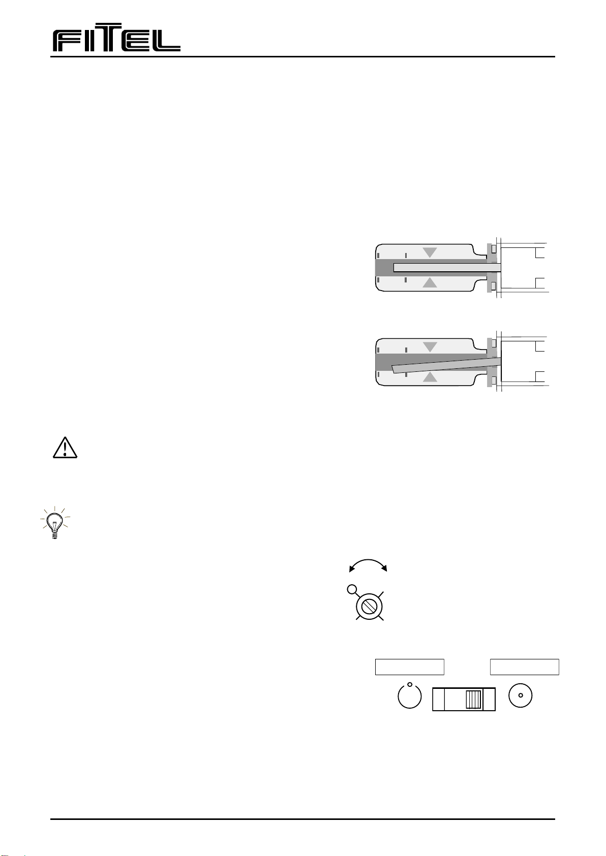
3) Hold the fiber with a fiber holder, with approximately 30mm (25 –35mm) of fiber end protruding from
the holder. Open the Holder clamp lid and the Heater lid, and place the fiber holder firmly in the Holder
clamp.
4) Ensure that the fiber rests in the heating area and the fiber
end is within Min. and Max. line of the Heater. Refer to the
drawing.
5) Close the Heater’s lid first, and then the Holder clamp lid.
6) Firmly grasp the Heater lid and the Holder clamp’s lid, and
wait until flashing of the indication LED stops.
Then, pull the holder clamp away from the Heater slowly.
(In case of the rollable-ribbon, pull more slowly)
7) Open the Holder clamp lid and the Heater lid and remove the
fiber holder.
8) Remove coating material refuse from the Heater and clean the heating area.
CAUTION : Do not touch the Heater.
9) When finishing to working of S218R-plus, press power switch again.
If not used the S218R-Plus will auto power off after 10 minutes. (Auto Power OFF)
7 Adjusting temperature
The temperature can be changed by rotating
temperature trimmer. (Refer to right drawing.)
Each scale shows 20 degree C step.
8 Setting power save mode
Save mode saves consumption of electrical power.
The mode is set to Normal mode at shipping.
The mode can be changed by setting mode switch to “SAVE”
position.
In the save mode, S218R-Plus cuts heater power and reduces the power consumption to a few mA during
the waiting time.
So it will take more time to raise the heater temperature enough for use after leaving in this mode for a
few minutes.
Proper Placement
Improper Placement
MODE
NORM
SAVE
Save mode
Normal mode
L
H
TEMP
100℃
120℃
80℃
140℃
FTS-B553-04
10
9 Recharging Battery
Attach S944 battery to the S218R-Plus and charge it using S952 AC adapter.
10 Confirming Battery Remaining
During using S218R with S944 battery, continuing to press the power switch for more than 2 seconds will
cause the S218R to show the battery power remaining with indication lamp. (Green/Red LED)
Each state of LED shows the condition of the battery and remaining power as per following table.
Remaining (%)
100
───
90
───
70
───
20
───
State of LED
Green
Green Blinking
Red Blinking
Red
If remaining power becomes less than 10%, the LED will blink even during using.
11 Maintenance
As a routine maintenance procedure, please clean the blade and heater area by using the brush or
air-blow gun periodically.
If there are some dusts or residue remaining in the blade and heater area, stripping process may not be
smooth . As a result, the operation may fail.
12 Replacing the blade
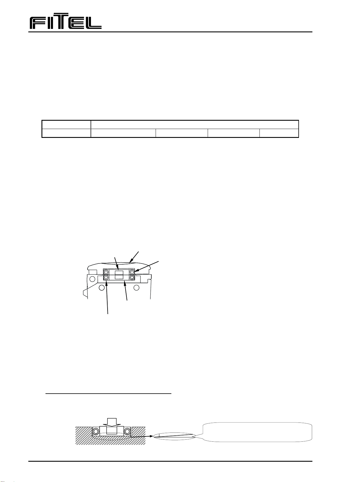
12.1 Replacing the lower blade
1) Remove two lower blade set screws, and take off the lower blade.
2) Set the new lower blade temporarily with the set screw tightened slightly.
Blade can be adjusted manually with light touch behind body.
3) Pushing down the lower blade to the bottom frame and fix it by means of tighten the set screw while
pushing the blade downward. Use torque wrench and tighten the screw with 1.2Kg・cm.
**Take care not to over-tighten the set screw.
4) After fixing, make sure of that there is no clearance between main frame and blade.
*Blade position cannot be adjusted if the set screw is over-tightened at fixation as number 2).
2 of Upper blade set screw (2-M2×1.5mmL)
2 of Lower blade set screw(2-M2×1.5mmL)
2 of Upper blade adjusting screw (0.9mm)
Upper blade
Lower blade
Fix the blade by tightening the set screw while pushing the blade downward.
There is no clearance between blade
bottom and main frame
FTS-B553-04
11
12.2 Replacing the upper blade
1) Loosen two upper blade adjusting screw with attached 0.9mm hex wrench.
Do not remove the screw, only loosen it.
2) Remove two upper blade set screws, and take off the upper blade.
3) Set the new lower blade tentatively with the set screw tightened slightly.
Blade can be adjusted manually with light touch behind body.
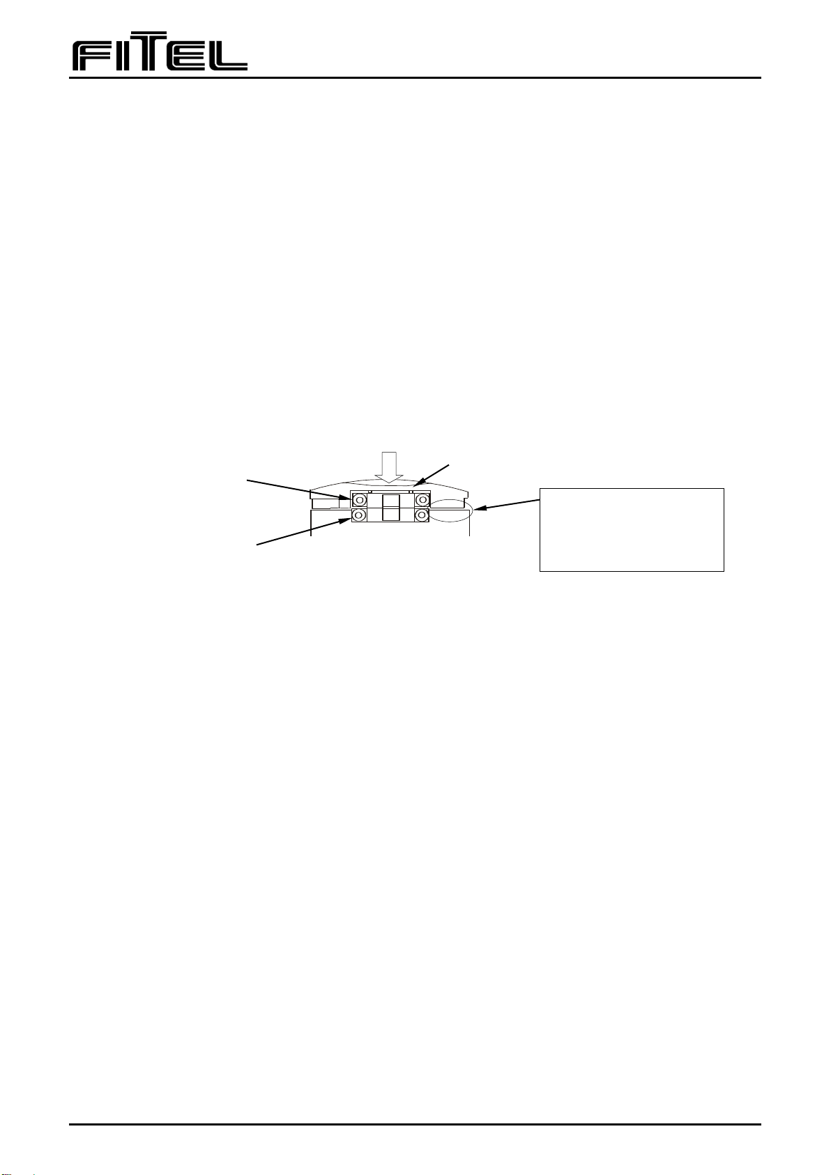
12.3 Upper blade adjustment
1) On the above condition, close the lid and tighten the two upper blade adjustment screws gradually
while pressing firmly on the PUSH portion of the lid. Tighten both sides screw alternately until the
full length of upper blade tip to touches lower blade tip.
The clearance between lid and body is approximately 0.1mm
Refer to the next page illustration.
2) Set the upper blade by tightening the set screw while pressing firmly on the PUSH portion of the lid.
Use the torque wrench and tighten the screw with 1.2Kg・cm.
*Same blade shape as upper blade and lower blade.
*Both blades should be replaced at the same time.
Upper blade set screw
(2-M2×1.5mm)
Lower blade set screw
(2-M2×1.5mm)
Upper blade adjustment screw
Adjust the upper blade while pressing PUSH marked position.
Target clearance
Adjust it in about 0.1 mm
clearance (Almost one piece
of paper).
FTS-B553-04
12
13 Others
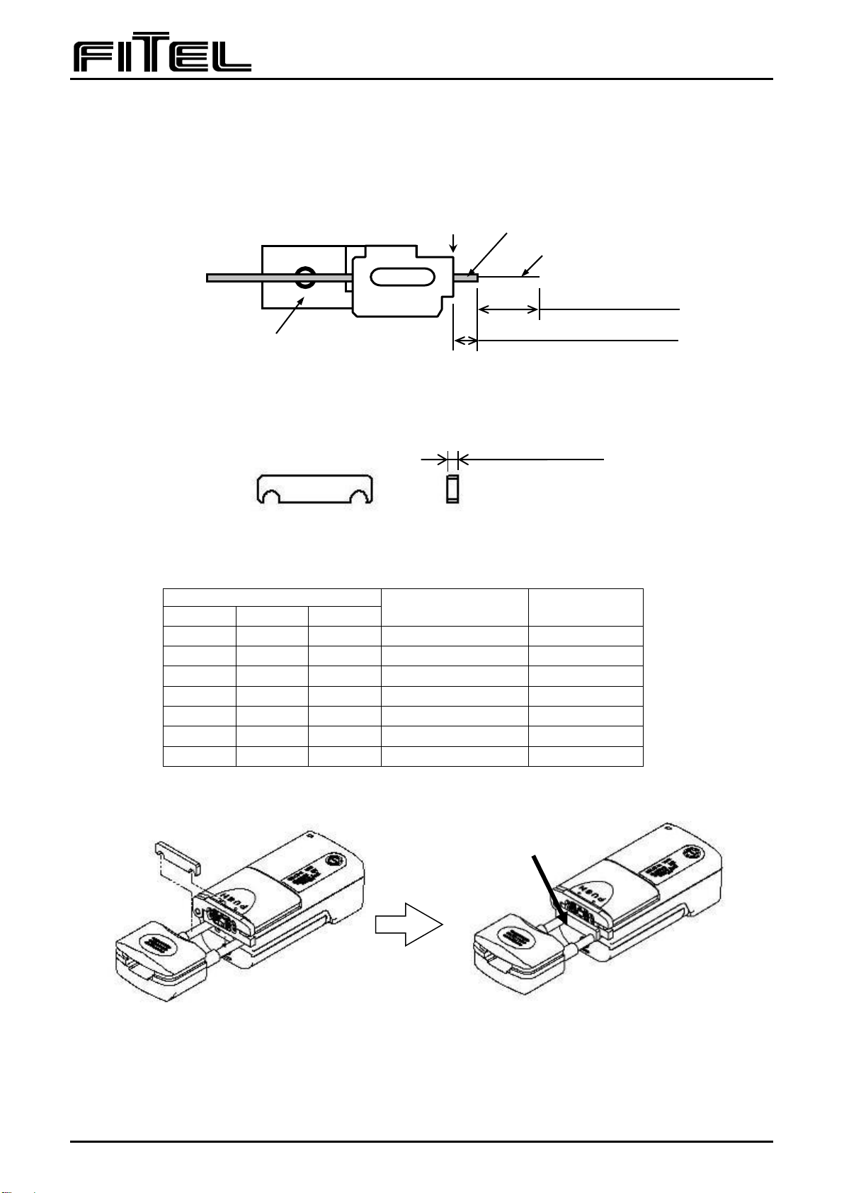
13.1 The usage of the Adjusters (spacer)
The adjusters is used when changing cleave length.
The adjuster has three kinds of thickness: 1mm, 2mm and 3mm.
Following is a guide table showing how to use the adjuster and its combination to make right stripping
length.
adjuster
Fiber coating length
(X)
Cleave length
(Y)
1mm
2mm
3mm
×
×
×
3mm
10mm
○
×
×
4mm
9mm
×
○
×
5mm
8mm
×
×
○
6mm
7mm
○
×
○
7mm
6mm
×
○
○
8mm
5mm
○
○
○
9mm
4mm
The sketches below show hot to put adjuster on to the unit.
Cleave length (Y)
Fiber coating
Fiber Clad
Fiber holder
Head of fiber holder
Fiber coating length (X)
1mm,2mm,3mm

FTS-B553-04
13
13.2 Mounting the Stand (Optional parts) for the unit
1) Remove the Battery cover.
2) Put the stand to the unit, then tighten the screw.
13.3 Single fiber adapter (Optional parts) installation.
(Applicable single fiber:Φ0.25mm~Φ0.4mm)
1) Set the single fiber upper adapter to surface of lid with set screw.
Refer to the illustration as below. (4-M2×6mmL screw)
2) Set the single fiber lower adapter to upper surface of body with set screw.
Refer to the illustration as below. (2-M2×8mmL screw)
Single fiber adapter lower set screw
2 - M2×8mmL
Single fiber adapter upper set screw
4 - M2×6mmL
Single fiber upper adapter
Single fiber lower adapter
Remove the Battery cover
Screw the stand
FTS-B553-04
14
13.4 Storage for the S944 Battery Pack
If S944 Battery Pack needs to be stored for more than 1 month without being used, please store it
using the following procedure.
1) Remove the S944 Battery Pack from S218R-Plus Main body, then move that to proper storage
area.
2) Maintain the storage environment under following conditions, temperature: -20°C to +20°C, and
humidity: 15 to 95 %RH without condensing.
3) Charge the Battery approximately 30 minutes every 6 months.
(Caution: If the Battery is over discharge, it may be unusable.)
14 Holding period for spare parts
We will have and hold the spare parts for repair and replacement at least 6 years after these products
are discontinued for production. During the period, we will repair this product.
Beyond the period, we may be able to repair this product depending on the problems, please contact
Furukawa electric Co., LTD or your local sales representative for further assistant.
15 Contacts
For sales and service information,
contact FURUKAWA ELECTRIC CO.,LTD.
or your local representative.
2-3 Marunouchi 2-chome, Chiyoda-ku, Tokyo, 100-8322 Japan
Global Sales & Marketing
Furukawa Electric Co., Ltd.
TEL:+81-3-3286-3253 FAX:+81-3-3286-3978

Table of contents
Other Fitel Tools manuals

Popular Tools manuals by other brands


FRIATEC
FRIATEC FWSG 63 operating instructions

Sioux Tools
Sioux Tools 8020ES Instructions-parts list

Husky
Husky 32215 Assembly, Installation, Operation and Maintenance Instructions

Wedge Clamp Systems Inc.
Wedge Clamp Systems Inc. CHAINLESS ANCHORING SYSTEM user manual

Wolfcraft
Wolfcraft 4650000 manual

Bosch
Bosch PTK 14 EDT Original instructions


