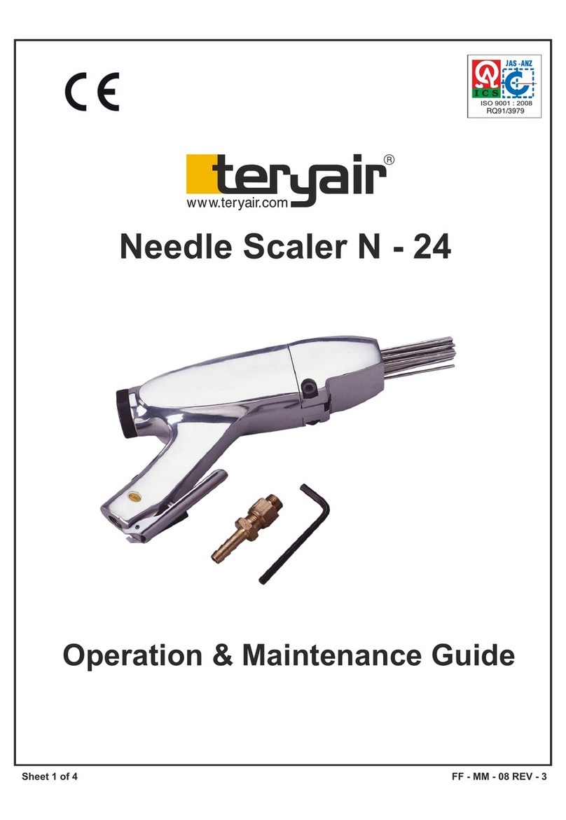
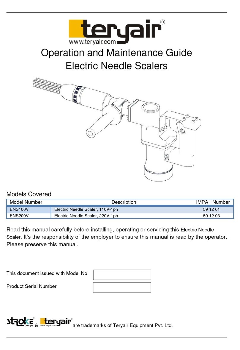
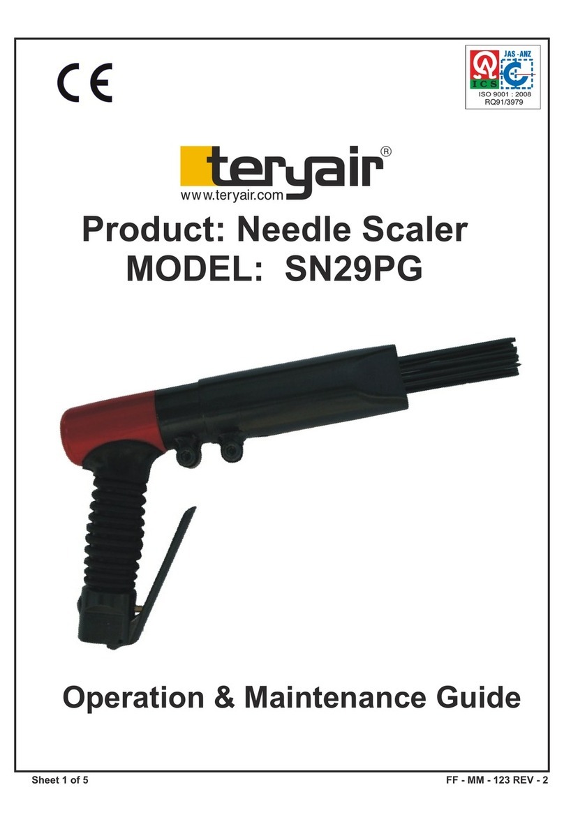
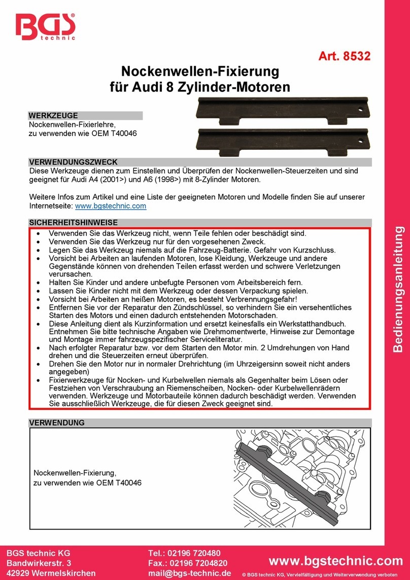
Teryair SN24ST Instruction Manual

Models Descriptions IMPA Code
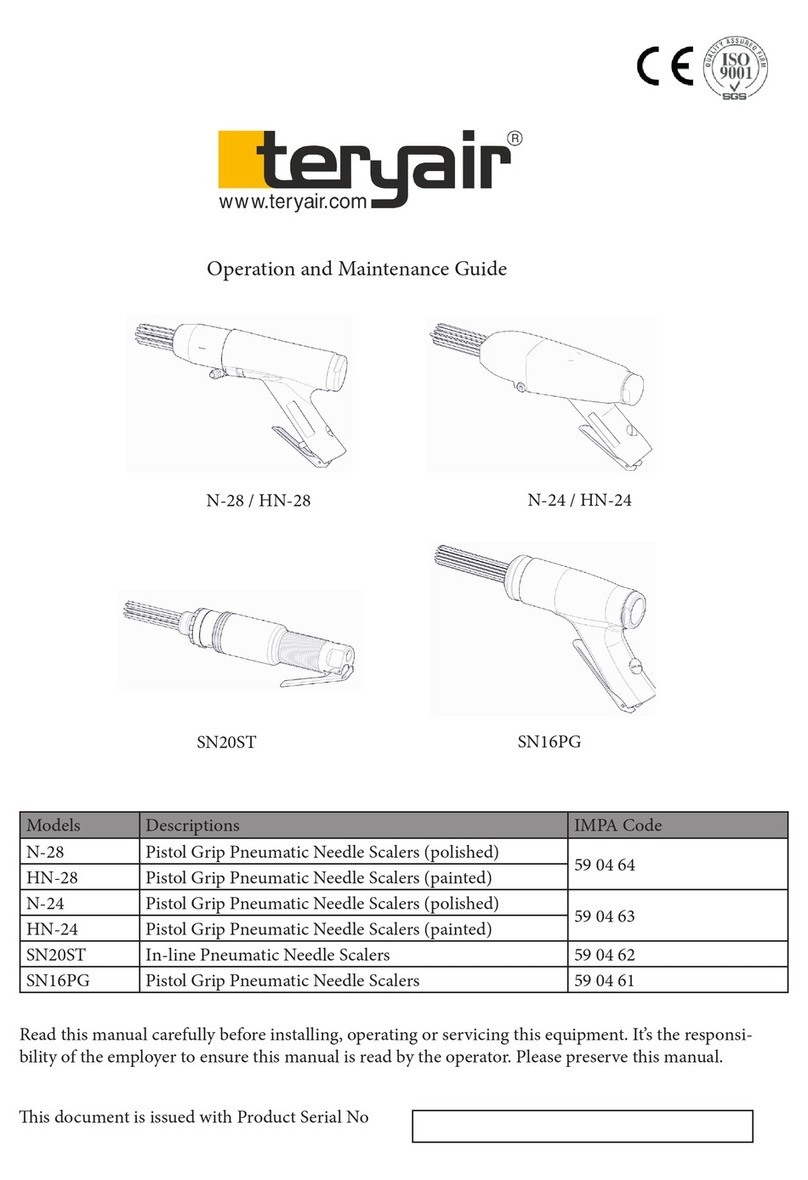
SN24ST In-line Pneumatic Needle Scalers 59 04 81
SN24PG Pistol Grip Pneumatic Needle Scalers 59 04 82
SN29PG Pistol Grip Pneumatic Needle Scalers 59 04 83
SN39STVL In-line Pneumatic Needle Scalers 59 05 18
SN39PGVL Pistol Grip Pneumatic Needle Scalers 59 05 00
SN45PGVL Pistol Grip Pneumatic Needle Scalers 59 05 10
Read this manual carefully before installing, operating or servicing this equipment. It’s the responsi-
bility of the employer to ensure this manual is read by the operator. Please preserve this manual.
is document is issued with Product Serial No
Operation and Maintenance Guide
SN24ST
SN24PG SN29PG
SN39STVL
SN39PGVL SN45PGVL

FF-MM-300-REV - 00
Page 2
Operation and Maintenance Guide Pneumatic Needle Scalers
Table of Contents
3 Introducon
3 Technical Data
3 SafetyInstrucons
4 OperangInstrucons
5 SuggestedLubricants
5 DiassemblyandRe-assemblyforSN24ST
6 ExplodedViewforSN24ST
7 BillofMaterialsforSN24ST
8 DiassemblyandRe-assemblyforSN24PG
9 BillofMaterialsforSN24PG
10 ExplodedViewforSN24PG
11 DiassemblyandRe-assemblyforSN29PG
12 ExplodedViewforSN29PG
13 BillofMaterialsforSN29PG
14 DiassemblyandRe-assemblyforS39PGVL
15 BillofMaterialsforSN39PGVL
16 ExplodedViewforSN39PGVL
17 DiassemblyandRe-assemblyforS39STVL
18 BillofMaterialsforSN39STVL
19 ExplodedViewforSN39STVL
20 DiassemblyandRe-assemblyforSN45PGVL
21 BillofMaterialsforSN45PGVL
22 ExplodedViewforSN45PGVL
23 TestCercateOfMaterials,Performance
24 EuDeclaraonOfConformity
25 WarrantyCercate

FF-MM-300-REV - 00
Page 3
Operation and Maintenance Guide Pneumatic Needle Scalers
Introduction
Teryair needle guns are rugged tools. ey are designed to be easy to use and maintain. ey are
ideal for removing layers of paint, corrosion and chemical coatings etc. from metal and non
metal surfaces. ese tools work well on irregular surfaces and in crevices and corners. e
needles are heat treated and are quickly replaceable.
Technical Data
Models
IMPA
Number
equiva-
lent
Maximum
operating
pressure
Air
Consumption
(No Load)
Blows
per
min
Sound
Power
Level
(Load)
Vibra-
tion
Level
Mass
(Weight)
Thread
Size
of Air
Inlet
Needles
CFM m3/
min (BPM) LwA b(A) m/s2 Kg
SN24ST 59 04 81
6kg/cm2
(90 psi)
5.5 0.16 3000 113.3 9.3 2.6 1/4" 3mm x
19 Nos.
SN24PG 59 04 82 5.5 0.16 3000 113.3 12.6 2.6 1/4" 3mm x
19 Nos.
SN29PG 59 04 83 8 0.23 2200 114.5 18.9 3.7 1/4" 3mm x
28 Nos.
SN39STVL 59 05 18 4 0.11 2400 90.7 2.56 2.4 1/4" 3mm x
19 Nos.
SN39PGVL 59 05 00 4 0.11 2400 90.7 2.75 2.7 1/4" 3mm x
19 Nos.
SN45PGVL 59 05 10 5.5 0.16 3000 109.5 2.3 3.5 1/4" 3mm x
28 nos.
Warning
is manual must be read and the operating
instructions carefully followed.
Warning
Safety and protective clothing, eyewear, head-
gear, ear protection, gloves and footwear to be
worn during operation of this Pneumatic Needle
Scaler. Please see Table A at end of this section.
Warning
Operators under 18 not allowed to operate this
Pneumatic Needle Scaler. Operators must be
made familiar with the instructions in this
manual before attempting to operate the
Pneumatic Needle Scaler. Ensure that job site is
clear of by standers
Caution
Use only genuine Teryair or Teryair approved
accessories.
Intended Use
Needle scalers are used for surface prepara-
tion work involving the cleaning or removal
of paint, rust, dirt, or weld slag from metal &
non - metal surfaces. ese tools also work well
on irregular surfaces such as crevices & cor-
ners. e needles are heat - treated & quickly
replaceable. Needle scalers are used in marine,
oshore & petrochemical plants.
Safety Instructions
Following symbols are used through out this
manual.

FF-MM-300-REV - 00
Page 4
Operation and Maintenance Guide Pneumatic Needle Scalers
• Eye and faceand ear protection must be worn
at all times during operation of the
Pneumatic Needle Scaler. ere is a chance
of ying debris from the jobsite and the
quality of wear should be such to protect
against such ying debris such as akes of
the removed layer.
• Suitable gloves must be worn at all times
during operation.
• Safety Shoes with toe cap protection are a
must during operation.
• Scalers are rugged dependable tools designed
to give you years of satisfactory service.
Follow the instructions mentioned here to
enhance life and performance of your scalers.
Daily Before Operating
Disconnect and pour in 1 to 2 ounces of
recommended oil into the Pneumatic Needle
Scaler and reconnect hose aer blowing out any
accumulated dirt in the hose line before
connection
Lubrication Requirements
Always install a line lubricator on the air line as
close to the Pneumatic Needle Scaler as possible.
A Filter Regulator Lubricator unit (FRL)is
strongly recommended. Keep the lubricator bowl
topped up with recommended grade of oil and
check that the oil is reaching the Pneumatic Nee-
dle Scaler. Running the Pneumatic Needle Scaler
without lubrication is likely to cause damage to
the components causing premature replacement.
Operating Instructions
Warning
is Pneumatic Needle Scaler is not designed
for use in an explosive environment.
Caution
Completely turn o the Pneumatic Needle
Scaler and disconnect air supply line before
attempting any service. Read Assembly and
Disassembly instructions.
Warning
Take care not to exceed the maximum 6 bar
(90 psi) supply air pressure. Use a lter and
regulator and lubricator as close to the Pneu-
matic Needle Scaler inlet as operation will
allow ensuring a clean and regulated and
lubricated air ow.
Caution
Do not exert excessive pressure against the
work surface. Keep hoses in good condition.
Check hoses for signs of wear, cracks & bulges
and ensure that they are secure. Accidental
disconnection while hose is pressurized makes
the hose whip and can be a safety hazard.
Caution
• Please check the hose connection prior to
starting Needle Scaler.
• Be aware that these Pneumatic Needle
Scalers can create dust & ying debris.
• Keep hands & clothing away from moving
parts.
• Store these Pneumatic Needle Scalers in
secure & dry environment.
• Do not allow the Pneumatic Needle Scaler
to run unattended.
• Do not modify this Pneumatic Needle
Scaler in any way as this will invalidate the
warranty and could lead to serious injury.
• Do not allow the Pneumatic Needle Scaler
to run continuously whilst not in contact
with the surface being prepared.
• Do not hold the exposed needles whilst
the Pneumatic Needle Scaler is in use
this could cause vibration damage to the
hands.
• Do not drag this Pneumatic Needle Scaler
by air hose.
Warning
Do not use the Pneumatic Needle Scaler in
potentially explosive environments.

FF-MM-300-REV - 00
Page 5
Operation and Maintenance Guide Pneumatic Needle Scalers
Suggested Lubricants
Brand Above 27C / 80F 5C to 27C / 41F to 80F Below 5C / 80F
Shell Toona R 72 Toona R 41 Toona R 27
Mobil Almo 529 Almo 527 Almo 525
Esso -- Arox EP.65 Arox EP.45
Caltex Rando Oil 100 Rando Oil 100 Rando Oil 46
Cp -- -- Airolene Tool OiI
Texaco Regal Oil F (R&O) Regal Oil PE(P&E) Regal Oil PE(R&O)
Daltron Silkolene 881 Silkolene 548/T Silkolene 733
Burmah Castrol Castrol RD Oil 3 Castrol RD Oil Light Megna SPX
Duckham Garnet 7 Garnet 6 Zero Fio 5
Sternol Merlin 87 Merlin 71 Merlin 54
Petrona Purifoc 53 Purifoc 46 Purifoc 32
Chevron Vistac Oil 18X Vistac Oil 19X Vistac Oil 9X
Indoil Servo Spyn -22 -- --
Air Supply
e Scalers work best at 6.2 bar (90 psi) air pres-
sure. e air should be clean, dry and lubricated.
Install a FRL unit as close as operation will
permit.
Hoses
Daily before operation check the hoses, especially the
high pressure hoses for damage or leaks
Use genuine Teryair spares and if possible mention the
serial number of the Pneumatic Needle Scaler when
ordering spares. Use genuine Teryair spares and if pos-
sible mention the serial number of the Pneumatic
Needle Scaler when ordering spares.
a. Shut o the air supply and allow residual
Pressure to bleed o.
b. Unscrew Allen Bolt (19) from Straight
Front Tube (16). Now remove Straight
Front Tube (16).
c. Unscrew similar Allen Bolt (19) from Inter-
mediate Tube (17). Now remove Interme-
diate Tube (17), Anvil (14), Needle Holder
(15) with Needles (20), and Compression
Spring (18) and replace it with new ones. (If
found damaged/worn-out)
d. Unscrew Valve Body (5) from Main Body
(1). Now remove Piston (3), O-ring (2), and
Sleeve Grip (4) from Main Body (1).
Diassembly and Re-assembly for SN24ST
e. Unscrew Valve Cap (6) with O-ring (7) from
Valve Body (5). Now remove Valve Spring
(8), Valve Stem (9), and O-ring (10) from
Valve Body (5) and replace them with new
ones. (If found damaged/worn-out).
f. Remove O-ring (7) from Valve Cap (6) and
replace it with the new one.
g. Remove Roll Pin (12) from Valve Body (5).
Now remove rottle Lever (11) from Valve
Body (5).
h. Coat parts with the recommended light oil
before re-assembling. Now follow the above
steps in a reverse manner to reassemble the
Needle Scaler.

FF-MM-300-REV - 00
Page 6
Operation and Maintenance Guide Pneumatic Needle Scalers
6
7
1
2
3
14
4
5
8
9
10
12
13
11
15
16
17
19
18
20
Exploded View for SN24ST

FF-MM-300-REV - 00
Page 7
Operation and Maintenance Guide Pneumatic Needle Scalers
Bill of Materials for SN24ST
Illustration
Number Part Number Description SN24ST
1 112 21 01 MAIN BODY 1
2 112 40 11 O' RING FOR MAIN BODY 1
3 112 21 02 PISTON 1
4 112 40 12 SLEEVE GRIP 1
5 112 21 07 VALVE BODY 1
6 100 21 06 VALVE CAP 1
7 100 40 15 O' RING - VALVE CAP 1
8 100 51 14 VALVE SPRING 1
9 100 25 11 VALVE STEM 1
10 124 40 01 O' RING - VALVE SEAT 1
11 100 30 12 THROTTLE LEVER 1
12 100 50 19 ROLL PIN (Ø3.17 x 25/26) 1
13 100 40 18 PLASTIC PLUG 1
14 112 21 03 ANVIL 1
15 112 21 04 NEEDLE HOLDER (Ø3) 1
16 112 32 13 STRAIGHT FRONT TUBE 1
17 112 32 14 INTERMEDIATE TUBE 1
18 112 51 15 COMPRESSION SPRING 1
19 200 90 68 CAP HEAD SCREW (M8X30) 2
20 022 90 04BL NEEDLE (Ø3 X 180) 19
Optional Accessories
Part No Description Qty
112 21 16 NEEDLE HOLDER (Ø2 OPTIONAL) 1
022 90 08BL NEEDLE (Ø2 X 180) 51

FF-MM-300-REV - 00
Page 8
Operation and Maintenance Guide Pneumatic Needle Scalers
Diassembly and Re-assembly for SN24PG
a. Shut o air supply and allow residual Pres-
sure to bleed o.
b. Unscrew Allen Bolt (21) from Straight
Front Tube (18) & remove.
c. Unscrew similar Allen Bolt (21) from In-
termediate Tube (19) & remove Anvil (16),
Needle Holder (17) with Needles (22) and
Compression Spring (20) from Intermedi-
ate Tube (19) and replace it with new ones.
(If found damaged/worn-out)
d. Unscrew Cylinder (1) from Cover Assem-
bly (6), Now remove Piston (4), O-ring
(3),& O-ring (2) from Cylinder (1) and
replace it with new ones (If found dam-
aged/worn-out).
e. Unscrew Valve Body (7) from Cover Assem-
bly (6) & remove rubber handle grip (5).
f. Unscrew Valve Cap (8) with O-ring (9) on
Valve Body (7). Now remove Valve Spring
(10) and Valve Stem (11) with O-ring (12)
from Valve Body (7) and replace with new
ones. (If found damaged/worn-out)
g. Remove O-ring (9) on Valve Cap (8) and
replace with new one.
h. Remove Roll Pin (14) on valve body (7) &
remove throttle Lever (13).
i. Coat parts with the recommended light oil
before re-assembling. Now follow the above
steps in reverse manner to reassemble the
Needle Scaler.

FF-MM-300-REV - 00
Page 9
Operation and Maintenance Guide Pneumatic Needle Scalers
Bill of Materials for SN24PG
Illustration
Number Part Number Description SN24PG
1 110 21 02 CYLINDER 1
2 110 40 03 “O” RING FOR CYLINDER 1
3 110 40 04 “O” RING FOR CYLINDER 1
4 112 21 02 PISTON 1
5 100 40 17 RUBBER HANDLE GRIP 1
6 110 97 06 COVER ASSY 1
7 100 21 07 VALVE BODY 1
8 100 21 06 VALVE CAP 1
9 100 40 15 “O” RING – VALVE CAP 1
10 100 51 14 VALVE SPRING 1
11 100 25 11 VALVE STEM 1
12 124 40 01 “O” RING – VALVE SEAT 1
13 100 30 12 THROTTLE LEVER 1
14 100 50 19 ROLL PIN 1
15 100 40 18 PLASTIC PLUG 1
16 112 21 03 ANVIL 1
17 112 21 04 NEEDLE HOLDER (Ø3) 1
18 112 32 13 STRAIGHT FRONT TUBE 1
19 112 32 14 INTERMEDIATE TUBE 1
20 112 51 15 COMPRESSION SPRING 1
21 200 90 68 CAP HEAD SCREW (M8X30) 2
22 022 90 04BL NEEDLE (3 X 180MM) 19
Optional Accessories
Part No Description Qty
022 90 08 NEEDLE (2 X 180 MM) 51
100 21 23 NEEDLE HOLDER (Ø2 ) 1

FF-MM-300-REV - 00
Page 10
Operation and Maintenance Guide Pneumatic Needle Scalers
Exploded View for SN24PG
21
18
19
20
17
22
16
6
4
2
3
1
5
13
8
9
10
11
12
7
15
14

FF-MM-300-REV - 00
Page 11
Operation and Maintenance Guide Pneumatic Needle Scalers
Diassembly and Re-assembly for SN29PG
a. Shut o the air supply and allow residual
Pressure to bleed o.
b. Unscrew Allen Bolt (11) from Straight
Front Tube (6). Now remove Straight
Front Tube (6).
c. Unscrew similar Allen Bolt (11) from In-
termediate Tube (7). Now unscrew Inter-
mediate Tube (7) from Cylinder (1).
d. Remove Anvil (8), Needle Holder (9) with
Needles (10), and Compression Spring (5)
from Intermediate Tube (7) and replace it
with new ones. (If found damaged/worn-
out)
e. Unscrew Cylinder (2) from Cover Assem-
bly (1), Now remove O-ring (4), O-ring
(20), and Piston (3) from Cylinder (2) and
replace it with new ones.
f. Unscrew Valve Body (19) from Cover Assem-
bly (1).
g. Unscrew Valve Cap (13) with O-ring (15)
from Valve Body (19). Now remove Valve
Spring (14) and Valve Stem (12) with O-ring
(18) from Valve Body (19) and replace them
with new ones. (If found damaged/worn-out)
h. Remove O-ring (15) from Valve Cap (13) and
replace it with the new one.
i. Remove Roll Pin (17) from valve body (19).
Now remove rottle Lever (16) from valve
body (19).
j. Coat parts with the recommended light oil
before re-assembling. Now follow the above
steps in a reverse manner to reassemble the
Needle Scaler.

FF-MM-300-REV - 00
Page 12
Operation and Maintenance Guide Pneumatic Needle Scalers
Exploded View for SN29PG
13
20
19
18
12
15
14
17
22
21
4
3
2
8
10
9
5
7
11
6
1
16

FF-MM-300-REV - 00
Page 13
Operation and Maintenance Guide Pneumatic Needle Scalers
Bill of Materials for SN29PG
Illustration
Number Part Number Description SN29PG
1 100 97 16 COVER ASSEMBLY 1
2 100 21 02 CYLINDER 1
3 100 21 03 PISTON 1
4 100 40 12 O'RING FOR CYLINDER 1
5 100 51 08 COMPRESSION SPRING 1
6 100 24 09 STRAIGHT FRONT TUBE 1
7 100 24 10 INTERMEDIATE TUBE 1
8 100 21 04 ANVIL 1
9 100 21 05 NEEDLE HOLDER(Ø3) 1
10 022 90 04BL NEEDLE (Ø3 X 180) 28
11 200 90 68 CAP HEAD SCREW 2
12 100 25 11 VALVE STEM 1
13 100 25 06 VALVE CAP 1
14 100 51 14 VALVE SPRING 1
15 100 40 15 O' RING - VALVE CAP 1
16 100 30 12 THROTTLE LEVER 1
17 100 50 19 ROLL PIN 1
18 124 40 01 O' RING - VALVE SEAT 1
19 100 21 07 VALVE BODY 1
20 100 40 18 PLASTIC PLUG 1
21 100 40 13 O'RING FOR CYLINDER 1
22 100 40 17 RUBBER HANDLE GRIP 1
Optional Accessories
Part No Description Qty
100 21 22 NEEDLE HOLDER(Ø2) 1
100 21 23 NEEDLE HOLDER(Ø4) 1
022 90 08 NEEDLE (Ø2 X 180) 65
022 90 06 NEEDLE (Ø4 X 180) 14

FF-MM-300-REV - 00
Page 14
Operation and Maintenance Guide Pneumatic Needle Scalers
Diassembly and Re-assembly for S39PGVL
a. Shut o air supply and allow residual Pres-
sure to bleed o.
b. Unscrew Front tube (18) from Interme-
diate Tube (12). Now remove Insert for
Front Tube (16) and Front Spring (20)
from Front Tube (18).
c. Remove O-ring (17), Needle Holder (14)
with Needles (15) and Piston (10), Piston
Cushion (13) from Intermediate Tube
(12). Now remove Piston Ring (11) and
Valve Pin (9) from Piston (10) and replace
it with new ones. (If found damaged/
worn-out)
d. Unscrew Intermediate Tube (12) from
Cover Assembly (1).
e. Remove O-ring (4) from Guide Plate (2).
Now remove Ball Retaining O-ring (7) and
Ball (8) from Cylinder (6) and replace it
with new ones. (If found damaged/worn-
out)
f. Unscrew Valve Body (21) from Cover As-
sembly (1).
g. Remove Rubber Grip (19) from Cover As-
sembly (1) and replace with new ones. (If
found damaged/worn-out)
h. Unscrew Valve Cap (22) with O-ring (23)
from Valve Body (21). Now remove Valve
Spring (24), Valve Stem (25) and O-ring
(26) and replace with new ones. (If found
damaged/worn-out)
i. Remove O-ring (23) from Valve Cap (22)
and replace with new one.
j. Remove Roll Pin (28) from Valve body (21
& remove rottle Lever (27and replace
with new ones. (If found damaged/worn-
out).
k. Coat parts with the recommended light oil
before re-assembling. Now follow the above
steps in reverse manner to reassemble the
Needle Scaler.

FF-MM-300-REV - 00
Page 15
Operation and Maintenance Guide Pneumatic Needle Scalers
Bill of Materials for SN39PGVL
Illustration
Number Part Number Description SN39PGVL
1 136 97 01 COVER ASSEMBLY 1
2 136 21 02 GUIDE PLATE 1
3 136 40 09 GUIDE PLATE SEAL 1
4 100 40 12 O' RING FOR GUIDE PLATE 1
5 136 40 13 CYLINDER STEM REACTION RING 1
6 136 21 03 CYLINDER 1
7 022 90 30 BALL RETAINING 'O' RING 1
8 148 09 11 BALL 1
9 148 50 21 VALVE PIN 1
10 136 21 04 PISTON 1
11 136 36 08 PISTON RING 1
12 136 24 06 INTERMEDIATE TUBE 1
13 136 40 10 PISTON CUSHION 1
14 136 21 05 NEEDLE HOLDER (3MM) 1
15 022 90 04HTBL NEEDLE (Ø3 X 180) 19
16 136 40 12 INSERT FOR FRONT TUBE 1
17 100 40 13 O' RING FOR FRONT TUBE LOCKING 1
18 136 24 07 FRONT TUBE 1
19 100 40 17 RUBBER HANDLE GRIP 1
20 136 51 14 FRONT SPRING 1
21 100 21 07 VALVE BODY 1
22 100 21 06 VALVE CAP 1
23 100 40 15 VALVE CAP 'O' RING 1
24 100 51 14 VALVE SPRING 1
25 100 25 11 VALVE STEM 1
26 100 40 16 VALVE SEAT 'O' RING 1
27 100 30 12 THROTTLE LEVER 1
28 100 50 19 ROLL PIN 1
29 100 40 18 PLASTIC PLUG 1
Optional Accessories
Part No Description Qty
136 21 15 NEEDLE HOLDER (2MM) 1
022 90 08 NEEDLE (Ø2 X 180 ) 48

FF-MM-300-REV - 00
Page 16
Operation and Maintenance Guide Pneumatic Needle Scalers
Exploded View for SN39PGVL
1
19
22
18
16
12
13
20
14
15
10
9
11
6
875423
17
23
24
27
25
26
21
29
28

FF-MM-300-REV - 00
Page 17
Operation and Maintenance Guide Pneumatic Needle Scalers
Diassembly and Re-assembly for S39STVL
a. Shut o air supply and allow residual Pres-
sure to bleed o.
b. Unscrew Front tube (24) from Intermedi-
ate Tube (21) & remove Insert (23), Front
Spring (22).
c. Remove O-ring (26), Needle Holder (15)
with Needles (16) and Piston (11), Piston
Cushion (13) from Intermediate Tube
(21). Now remove Piston Ring (12) and
Valve Pin (14) from Piston (11) and re-
place it with new ones. (If found damaged/
worn-out)
d. Unscrew Intermediate Tube (21) from
Cover Assembly (1).
e. Remove O-ring (27) from Guide Plate (4)
& remove Ball Retaining O-ring (6) and
Ball (3) from Cylinder (5) Replace parts
with new ones. (If found damaged/worn-
out).
f. Unscrew Valve Cap (19) with O-ring (9) from
Cover Assembly (1) & remove Valve Spring
(17), Valve Stem (8) and O-ring (18). Replace
parts with new ones. (If found damaged/worn-
out).
g. Remove O-ring (9) from Valve Cap (19) and
replace with new one.
h. Remove Roll Pin (25) from Cover Assembly (1)
& remove rottle Lever (27) from Cover As-
sembly (1) and replace with new ones. (If found
damaged/worn-out).
i. Coat parts with the recommended light oil be-
fore re-assembling. Now follow the above steps
in reverse manner to reassemble the Needle
Scaler.

FF-MM-300-REV - 00
Page 18
Operation and Maintenance Guide Pneumatic Needle Scalers
Bill of Materials for SN39STVL
Illustration
Number Part Number Description SN39STVL
1 144 21 01 COVER ASSEMBLY (IN LINE) 1
2 100 30 12 THROTTLE LEVER 1
3 148 09 11 BALL 1
4 136 21 02 GUIDE PLATE 1
5 136 21 03 CYLINDER 1
6 148 40 12 BALL RETAINING 'O' RING 1
7 136 40 09 GUIDE PLATE SEAL 1
8 100 25 11 VALVE STEM 1
9 100 40 15 O' RING - VALVE CAP 1
10 136 40 13 CYLINDER STEM REACTION RING 1
11 136 21 04 PISTON 1
12 136 36 08 PISTON RING 1
13 136 40 10 PISTON CUSHION 1
14 148 50 21 VALVE PIN 1
15 136 21 05 NEEDLE HOLDER (3MM) 1
16 022 90 04HTBL NEEDLE (Ø3 X 180) 19
17 100 51 14 VALVE SPRING 1
18 124 40 01 O' RING - VALVE SEAT 1
19 100 21 06 VALVE CAP 1
20 100 40 18 PLASTIC PLUG 1
21 136 21 06 INTERMEDIATE TUBE 1
22 136 51 14 FRONT SPRING 1
23 136 40 12 INSERT FOR FRONT TUBE 1
24 136 24 07 FRONT TUBE 1
25 100 50 19 ROLL PIN 1
26 100 40 13 O' RING FOR FRONT TUBE LOCKING 1
27 100 40 12 O' RING FOR GUIDE PLATE 1
Optional Accessories
Part No Description Qty
136 21 15 NEEDLE HOLDER (2MM ) 1
022 90 08 NEEDLE (Ø2 X 180) 48

FF-MM-300-REV - 00
Page 19
Operation and Maintenance Guide Pneumatic Needle Scalers
Exploded View for SN39STVL
24
23
26
21
22
15
16
11
12 14 13
5
10 364727
2
25
1
20
18
8
17
9
19

FF-MM-300-REV - 00
Page 20
Operation and Maintenance Guide Pneumatic Needle Scalers
Diassembly and Re-assembly for SN45PGVL
a. Shut o air supply and allow residual Pres-
sure to bleed o.
b. Unscrew Front tube (17) from Interme-
diate Tube (8) & remove Insert (16) and
Front Spring (15).
c. Remove O-ring (10), Needle Holder (13)
with Needles (14) and Piston (11), Piston
Cushion (7) from Intermediate Tube (8).
Now remove Piston Ring (12) and Valve
Pin (19) from Piston (11) and replace it
with new ones. (If found damaged/worn-
out)
d. Unscrew Intermediate Tube (8) from Cov-
er Assembly (20).
e. Remove O-ring (10) from Guide Plate (4)
& remove Ball Retaining O-ring (3) and
Ball (2) from Cylinder (6) to replace it
with new ones. (If found damaged/worn-
out)
f. Unscrew Valve Body (21) from Cover
Assembly (20).
g. Remove Rubber Grip (1) from Cover
Assembly (20) and replace with new
ones. (If found damaged/worn-out)
h. Unscrew Valve Cap (22) with O-ring
(23) from Valve Body (21) & remove
Valve Spring (24), Valve Stem (25) and
O-ring (26) to replace with new ones. (If
found damaged/worn-out)
i. Remove O-ring (23) from Valve Cap
(22) and replace with new one.
j. Remove Roll Pin (28) from Valve body
(21) & remove rottle Lever (27) to re-
place with new ones. (If found damaged/
worn-out).
k. Coat parts with the recommended light
oil before re-assembling. Now follow the
above steps in reverse manner to reas-
semble the Needle Scaler.
This manual suits for next models
11
Table of contents
Other Teryair Tools manuals
