FITOP CTS Series User manual


To
Our Customer;
We
appreciate your purchase of our products and look forward to a
lasting relationship.
You
are now the owner of a new
FITOP
Electric Chain Hoist.
We
believe that our hoist products have many advanced features that will
minimize your maintenance requirements and bring you many years of
trouble free service.
We
recommend that you read this manual thoroughly prior to
installation of your new hoist or trolley. This manual has been provided
to assist you in the proper installation and operate of your new host or
trolley and will provide you with important safety and operation tips.
The safe operation of your new hoist is your most important concern.
Proper operation of your hoist will increase its longevity and minimize
your maintenance requirements.
Please study this manual thoroughly before installing your new hoist or
trolley.
CONTENT
CONTENT
CONTENT
CONTENT
1. Attention! Before Installation ...............................
1
2. Caution! Before Operating .................................
2
3. Examination and Maintenance ..............................
5
4.Troubles hooting and m aintenance ...........................
7
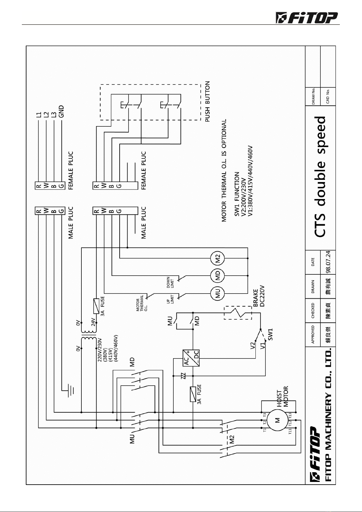
5.Circuit diagram ..........................................
9

- 1 -
1.
1.
1.
1. Attention!
Attention!
Attention!
Attention! Before
Before
Before
Before Installation:
Installation:
Installation:
Installation:
1.1
1.1
1.1
1.1 Check
Check
Check
Check Your
Your
Your
Your Shipment
Shipment
Shipment
Shipment for
for
for
for Damage:
Damage:
Damage:
Damage:
1.1.1 Check to see that the hoist or trolley (unit) h as bee n
delivered in good condition and that there are no v isibl e signs
of damage. Prior to shipment from the manufacturer e v ery
hoist and trolley is subjected to a strict quality control check.
However, unseen damage could occur during handling so it is
recommended that the customer perform the following tests.
1.1.2 Check the plug-in power cable to the hoist and/or trolley
with an Ohmmeter. The minimum resistance should be one
million Ohms as measured to ground.
1.1.3 Please check the plug-in push button and/or trolley motor
cable in the same manner.
1.2
1.2
1.2
1.2 Check
Check
Check
Check the
the
the
the Hoist
Hoist
Hoist
Hoist Load
Load
Load
Load Chain:
Chain:
Chain:
Chain:
1.2.1 Is the load chain twisted or damaged? Check to see that
the chain links that are 90 °to the lifting sprocket have the
We l ds facing ( away) out.
1.2.2 Is the load chain oiled? If not, please oil it.
1.2.3 See Picture 1 for proper chain bag installation.
1.3
1.3
1.3
1.3 Electrical
Electrical
Electrical
Electrical Hookup:
Hookup:
Hookup:
Hookup:
1.3.1 The plug-in power input cable is a four wire (R, S, T&E) “SO ”type cable equipped with a four-
conductor plug for your convenience. Connect the wires marked R, S and T the incoming power
source. If one of the three phases of the power source is connected to ground (Grounded Delta),
the wire marked S should be connect with the phase which is grounded.
1.3.2 The Green or E wire is the unit ground and must be securely connected to a clean-grounded
surface.
1.3.3 When installing a trolley care must be taken to see that the rail is properly grounded and the
contact surface (rail to wheel) is clean to minimize resistance.
1.4
1.4
1.4
1.4 After
After
After
After installation:
installation:
installation:
installation:
1.4.1 Check to see that the unit is phased properly. Depress the Up button, if the hook is lowered stop
immediately; disconnect the power and change phase, i.e., switch the R and T wires.
1.4.2 Test, does the hoist sound quite? If it is growling or sluggish stop immediately and disconnect the
incoming power! Check to see that the voltage is correct for this unit.
1.4.3
Test
the upper and lower limit with the hoist unloaded.
1.4.4 Instruct operators to perform these three testes at the beginning of each shift.
PICTURE 1

- 2 -
PICTURE 5PICTURE 4PICTURE 3
Hook Safety Patch
O
O
O
O X
X
X
X
PICTURE 7PICTURE 6
2.
2.
2.
2. Caution!
Caution!
Caution!
Caution! Before
Before
Before
Before Operating:
Operating:
Operating:
Operating:
2.1
2.1
2.1
2.1 Qualified
Qualified
Qualified
Qualified Operator:
Operator:
Operator:
Operator:
2.1.1 Only qualified personnel should be allowed to operate hoisting equipment.
2.1.2 Read this manual thoroughly (ref. Picture 2)
2.2
2.2
2.2
2.2 Correct
Correct
Correct
Correct Operation:
Operation:
Operation:
Operation:
2.2. 1 Never exceed the rated capacity of the hoist or trolley
2.2.2 It is required that you clearly mark the capacity of the hoist on the monorail or bridge beam
(ref. Picture 3) for the operator ' s reference.
2.2. 3 Use this and all hoisting equipment in a safe and proper manner. Improper or negligent use of this
equipment could result in bodily injury or death to the operator or surrounding personnel
(ref. Picture 4).
2.2.4 Do not remove the safety latch from the top or bottom hooks. The safety latch is designed to
secure the hook to the lifted load. It can prevent the load from slipping off the hook (ref. Picture 5).
Furthermore, local and national safety laws require all hoists to be equipped with safety latches.
2.2.5 Always center the hoist over the load to be lifted. Attempting to lift loads off center can result in
damage to the hoist or injury to the operator.
2.2.6 Before lifting a load examine it to insure that it is rigged properly and that it will not spill or topple
over causing damage or injury (ref. Picture 6).
2.2.7 Make sure the load to be lifted is free of any attachments such as chains, bindings or clamps.
While lifting the load (ref. Picture 7) take care that it does not snag or catch on stationary objects.
PICTURE 2

- 3 -
2.2.8 While operating two hoists in tandem, please note that the center of gravity must be equal.
(Ref.Picture 8). Never use three hoists simultaneously!
2.2.9 Never stand under the lifted load (ref. Picture 9)!
2.2.10 Never lift, support or otherwise transport people or suspend loads over people (ref. Picture 9)!
2.2.11 Caution! Always release the push button under the hoist. Do not release the button from a
distance, it could swing and injure someone (ref. Picture 10).
2.2.12 Frequently inspect all below hook lifting devises such as cable or chain slings for signs of
e xcessive wear, stretching or open hooks, replace any damaged slings immediately.
2.2.13 Do not pull the hoist by the push button cable (ref. Picture 11) instead push the lifted load.
2.2.14 Do not run the hoist into the end stops this could result in damage to the hoist and possible loss
of the load (ref. Picture 12).
2.2.15 While operating the push button, please push the buttons firmly excessive jogging (tapping) of
the push button causes high inrush currents and can result in motor overheating or premature
brake wear.
2.2.16 The Upper and lower limit switches are emergency safety stops and are not to be used as
automatic stop positions. Even though your hoist is equipped with an overload clutch do not
remove the limit switches (ref. Picture 13). If the limit switches do not function properly please
ask the maintenance department to repair or replace them immediately.
PICTURE 10PICTURE 9PICTURE 8
PICTURE 11 PICTURE 12 PICTURE 13

- 4 -
2.2.17 Your
FITOP
FITOP
FITOP
FITOP
hoist is furnished with grade #80 Super Alloy load chain. Corrosion will make the
load chain bind-up when passing over the load sprocket (ref. Picture 14). Keep the load chain
clean, free of rust and well oiled for proper operation and maximum life.
• The weld point of the chain link should be on the inside when it passes over the idler sprocket
(ref. Picture 15-A).
• With 2-fall hoist, care should be taken so as not to flip the hook 360 ° back through it and twist
the load chain (ref. Picture 1 5-B )
• Do not operate the hoist with twisted or damaged load chain.
2.2.18 Never side pull with your hoist, non-vertical lifts can damage your hoist limit switches, chain
guides and/or load chain (ref. Picture 16).
2.2.19
To
extend the service life of machine, please check the hoist periodically.
2.2.20 Please be aware of the position of the electric current switch. Shot down the switch if there ' s any
Emergency.
2.3
2.3
2.3
2.3 Safety
Safety
Safety
Safety Inspection
Inspection
Inspection
Inspection before
before
before
before Operation:
Operation:
Operation:
Operation:
To
To
To
To
insure
insure
insure
insure operator
operator
operator
operator safely
safely
safely
safely and
and
and
and extend
extend
extend
extend the
the
the
the service
service
service
service life
life
life
life of
of
of
of the
the
the
the hoist
hoist
hoist
hoist please
please
please
please perform
perform
perform
perform the
the
the
the
following
following
following
following safety
safety
safety
safety checks
checks
checks
checks listed
listed
listed
listed below.
below.
below.
below.
2.3.1 Check if the push button operates properly, Up is Up Down is down, etc.(ref. Picture 1 7 )
2.3.2 Check for proper operation of both the upper and lower limit switches with an unloaded (empty)
hook . (ref. Picture 1 8 )
2.3.3 Does the hook stop immediately when loaded? If not, check to determine whether the h o ok
drift(brake slip) is not more than 1/2 of 1% of the hoisting distance as traveled in one minute .
(ref. Picture 19)
2.3.4 Others Safety Checks: Listen for unusual noises such as squealing or grinding? Does the lower
hook swivel freely? Doe the hook show signs of overload, is the safety latch working? Is the load
chain twisted or damaged? Is the load chain lubricated? Are there any signs of excessive wear or
damage? Is the push button or cable damaged?
The
The
The
The regular
regular
regular
regular examinations
examinations
examinations
examinations can
can
can
can prevent
prevent
prevent
prevent accidents
accidents
accidents
accidents and
and
and
and prolong
prolong
prolong
prolong the
the
the
the life
life
life
life of
of
of
of your
your
your
your hoist.
hoist.
hoist.
hoist.
Same direction
Wrong direction
PICTURE 16A
PICTURE 17
PICTURE 15
PICTURE 18
B
PICTURE 19
PICTURE 14
Weld Point
Wrong direction

- 5 -
3.
3.
3.
3. Examination
Examination
Examination
Examination and
and
and
and Maintenance:
Maintenance:
Maintenance:
Maintenance:
3.1
3.1
3.1
3.1 Daily
Daily
Daily
Daily examination:
examination:
examination:
examination: Each
Each
Each
Each day
day
day
day perform
perform
perform
perform the
the
the
the following
following
following
following maintenance
maintenance
maintenance
maintenance checks
checks
checks
checks listed
listed
listed
listed below
below
below
below :
:
:
:
3.1.1 Is the up and down operation of the hoist correct?
3.1.2 Listen for any unusual noises?
3.1.3 Do the limit switches and the holding brake work correctly?
3.1.4 Does the hook rotate freely and is the latch working?
3.1.5 Is the load chain twisted or damaged?
3.1.6 Is the load chain clean, free of corrosion and well lubricated?
3.2
3.2
3.2
3.2 Monthly
Monthly
Monthly
Monthly examination:
examination:
examination:
examination:
3.2.1 Examination of load chain:
• Your FITOP electric chain hoist has been furnished with special calibrated grade #80 load chains
t hat a re available through FITOP authorized dealers only.
• The load chain must be replaced if it is stretched or worn beyond allowable, refer to diagram 20
f or proper chain specifications.(ref. Picture 20 )
• Do not use worn, damaged or stretched
load chain or attempt to repair it.
• Use the chain limit gauge (ref. Picture 21)
to test if the chain is within allowable limits,
if it is not it must be replaced immediately!
d .
Diameter
P.
Pitch
a .
Inside width
b .
Outside width
φ5.6 17.0 7.0 18.6
φ
7.1 20.2 8.9 23.2
φ
10.0 30.0 12.5 33.2
φ11.2 34.0 14.0 37.2
PICTURE 20
UNIT: mm Diagram: 20
PICTURE 2 1

- 6 -
3.2.2 Examination of the hoist holding brake is essential to the safe operation of your electric chain
hoist .
T
o check your brake for proper operation follow the instructions listed below (ref. Picture 22).
1Nut, Ny i stop type 4pcs
2
Nut, Ny i stop type 4pcs
3
Brake Coil Assembly
4Spring Closing
5
Feeler gap(Standard: 1~1.5mm)
6
Feeler gauge(1mm thick)
7Lock P l at e 1pcs
8
Nut Nyistop type 1pcs
• The method of adjust feeler gap :
(1)
To
open the brake end cover of hoist.
(2)
To
remove the feeler gauge ⑥f ro m the brake coil assembly ③.
(3) The feeler gauge
⑥
has been provided to measure the distance of feeler gap
⑤
. If the gap is larger
than 1.5mm, you need to adjust your brake.
(4)
To
adjust the nut ②which is on the brake coil assembly ③down to the appropriate seat .
(5) After adjusting, please to lock the nut
①
on the brake coil assembly
③
.
(6) Then put the feeler gauge ⑥into the feeler gap ⑤to adjust the gap around 1mm-1.5mm.
(7) After finish the above procedure, please put the feeler gauge ⑥back to the brake coil assembly ③.
(8) Closing the brake end cover of the hoist.
If there is slide situation after operating, please to adjust as picture 22 (Mark:
To
avoid
adjustment without authorization)
• The method of adjust load limiter :
(1)
To
open the brake end cover of hoist.
(2)
To
stretch the lock plate ⑦.
(3)
To
turn the nut
⑧
clockwise into the anchor stud then turning it counter clockwise so that will
increase the load about 1.25 times.
(4) Bending the lock plate ⑦to fix the nut ⑧.
(5) Closing the brake end cover of the hoist.
PICTURE 22

- 7 -
3.2.3 Examine the push button station (pendant):
• Is the push button case or cover broken or damaged in any way?
• Is the pendant cable cut or damaged?
• Does the pendant operate correctly?
• Any problems with the electrical operation such as intermittent contact?
• Is the plug clean and undamaged?
3.2.4 Examination of limit switches:
• Does the limit paddle move (rock) freely? If not check for damage or corrosion, possibly it needs
to be lubricated.
• Do the upper and lower limits operate correctly?
3.2.5 Examination of hoist hook . (ref. Picture 2 3 )
• Is the hoist hook bent or distorted? If so, it must be replaced. .
• If the hook saddle thickness (H) is reduced by 5 % of the hook thickness (ref Digraph 23) then the
hook must be replaced.
• If the shape of the width of edge changes (L), please change the hook immediately for safety
reason.
3.2.6 Examination of the chain container:
• Does the hoist hook or load chain catch on the container?
• Is the bag ripped or the frame bent or damaged?
• Any other object in the container except the chain?
3.2.7 Examination of the power cord and other electrical cables:
• Are any of the electrical cables pulled out?
• Are the cables damaged or cut?
• Are the plugs in good order and tight?
3.2.8 Examine all screws in insure a good tight connection.
4.
4.
4.
4. Troubles
Troubles
Troubles
Troubles hooting
hooting
hooting
hooting and
and
and
and maintenance:
maintenance:
maintenance:
maintenance:
4.1
4.1
4.1
4.1 Maintenance:
Maintenance:
Maintenance:
Maintenance:
4.1.1 Disconnect the power source and lock the box out prior to performing maintenance.
4.1.2 Do not leave any tools or parts on the trolley, hoist or rail.
PICTURE 23

- 8 -
4.2
4.2
4.2
4.2 Mechanism:
Mechanism:
Mechanism:
Mechanism:
Trouble Possible Cause Troubleshooting
Motor will
Not run.
1. Blown fuse or tripped circuit 1. Check your power source for blown(open)
breaker. fuses. With motorized trolley option check for
tripped circuit breaker in the trolley control box.
2. Motor has overheated. 2. Check the motor brake, is it releasing? Measure
the motor amperage, does it match the motor
name plate data? Note: Overloading or excessive
Jogging will cause high current draw, which in
turn will cause the motor to overheat.
3. Contactor malfunctions. 3. Replace the contactor.
4. Low Voltage. 4. Check the incoming voltage, is it correct?
5. Control circuit is off. 5. Check the control transformer output voltage is
the fuse blown (open)?
Examine for loose connections, broken switches
or damage to the cable or plug.
Motor
makes loud
growling or
buzzing noise
1. Wrong voltage. 1. Confirm that the voltage of your hoist matches
your power supply voltage.
2. Single phase condition. 2. Check your power source for blown (open)
fuses. Check the hoist contactor for loose wires
or burnt (open) contact point.
3. Motor has overheated. 3. Check the motor brake, is it releasing? Measure
the motor current draw, is it correct? Note:
Overloading or excessive jogging will cause high
current draw, which in turn will cause the motor
to overheat.
4. Damaged motor. 4. Check the motor windings, are they grounded?
Hoist
operates in
Only one
direction
1. Hoist Up motion only? The 1. Check the motor brake, is it releasing? Measure
motor O.L. has tripped(opened)
the motor current draw, is it correct? Note:
due to excessive overheating. Overloading or excessive jogging will cause high
current draw, which in tum will overheat the
motor
2.
Limit switch is tripped because
2. Side pulling will cause the limit paddle to trip,
side pulling. always center the hoist over the lifted load.
3. Limit paddle is bent or 3. Repair, lubricate or replace limit paddle.
corroded and sticking
4. Push button switch or cable is 4. Examine for loose connections, broken switches
broken. or damage to the cable or plug.
5. Contact point of magnetic 5. Install new magnetic contactor.
contactor burned (open)
Hoist brake
will not hold.
1. The distance between the 1. Adjust the brake according to the directions, air
brake magnet and armature Gap=1mm minimum to 1.5mm maximum.
Plate (air gap) is too large.
2. The brake is worn out. 2. W hen the lining wear is 50% the thickness of the
brake lining(3.5mm), the brake discs (pads)
must be replaced.
Remarks:
Remarks:
Remarks:
Remarks: Hoist
Hoist
Hoist
Hoist Motor
Motor
Motor
Motor has
has
has
has Class
Class
Class
Class H
H
H
H Insulation,
Insulation,
Insulation,
Insulation, Trolley
Trolley
Trolley
Trolley Motor
Motor
Motor
Motor has
has
has
has Class
Class
Class
Class E
E
E
E Insulation
Insulation
Insulation
Insulation

- 9 -
- 10 -

- 11 -
Table of contents
Popular Winch manuals by other brands


Harken
Harken 50.2 PTBBB Installation and maintenance manual

Greifzug
Greifzug Tirak T 1000 series Operation and installation manual

Comeup
Comeup Baby Winch CWS-300 manual

Harken
Harken Performa Winch 60.2 STP Installation and maintenance manual

Ingersoll-Rand
Ingersoll-Rand Force 5i Series Product Maintenance Information

Solid
Solid SW-V4012 user guide