tirak™
G932.1 - 06/2010 EN-DE-FR-NL–III
DE
FR
NL
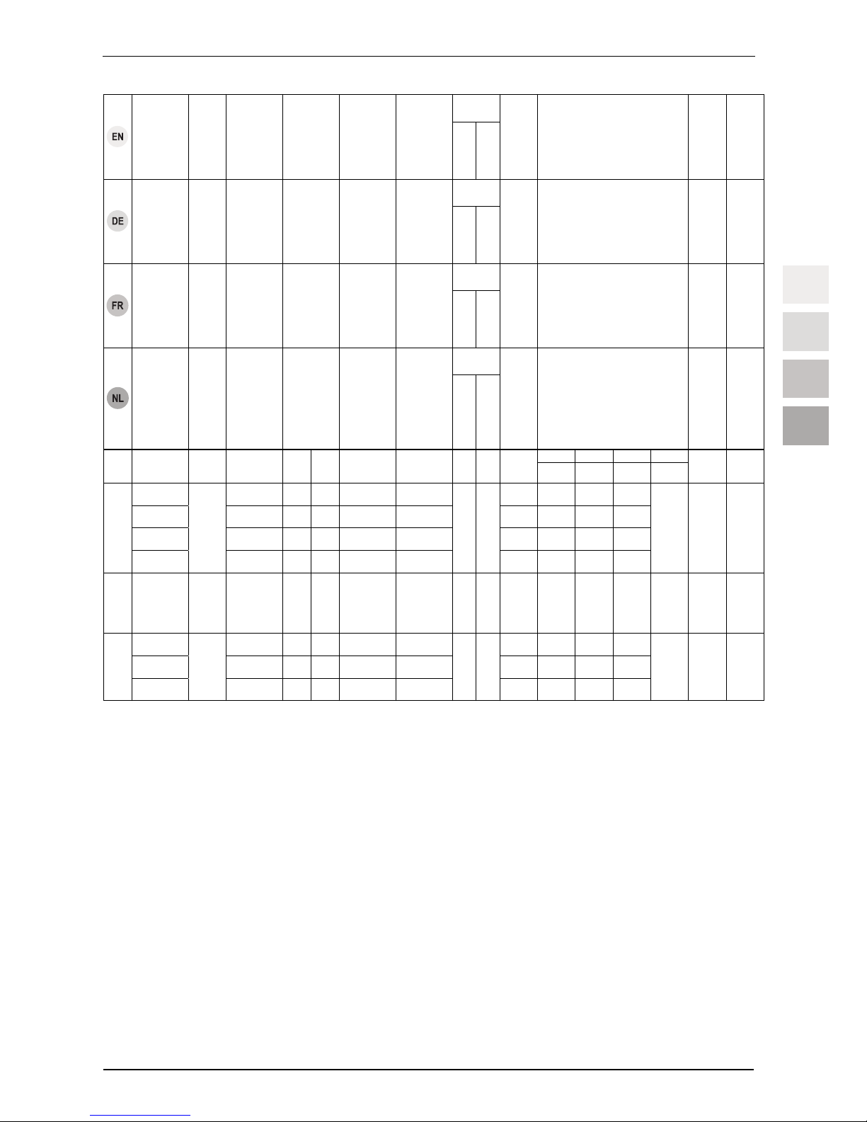
ENEN
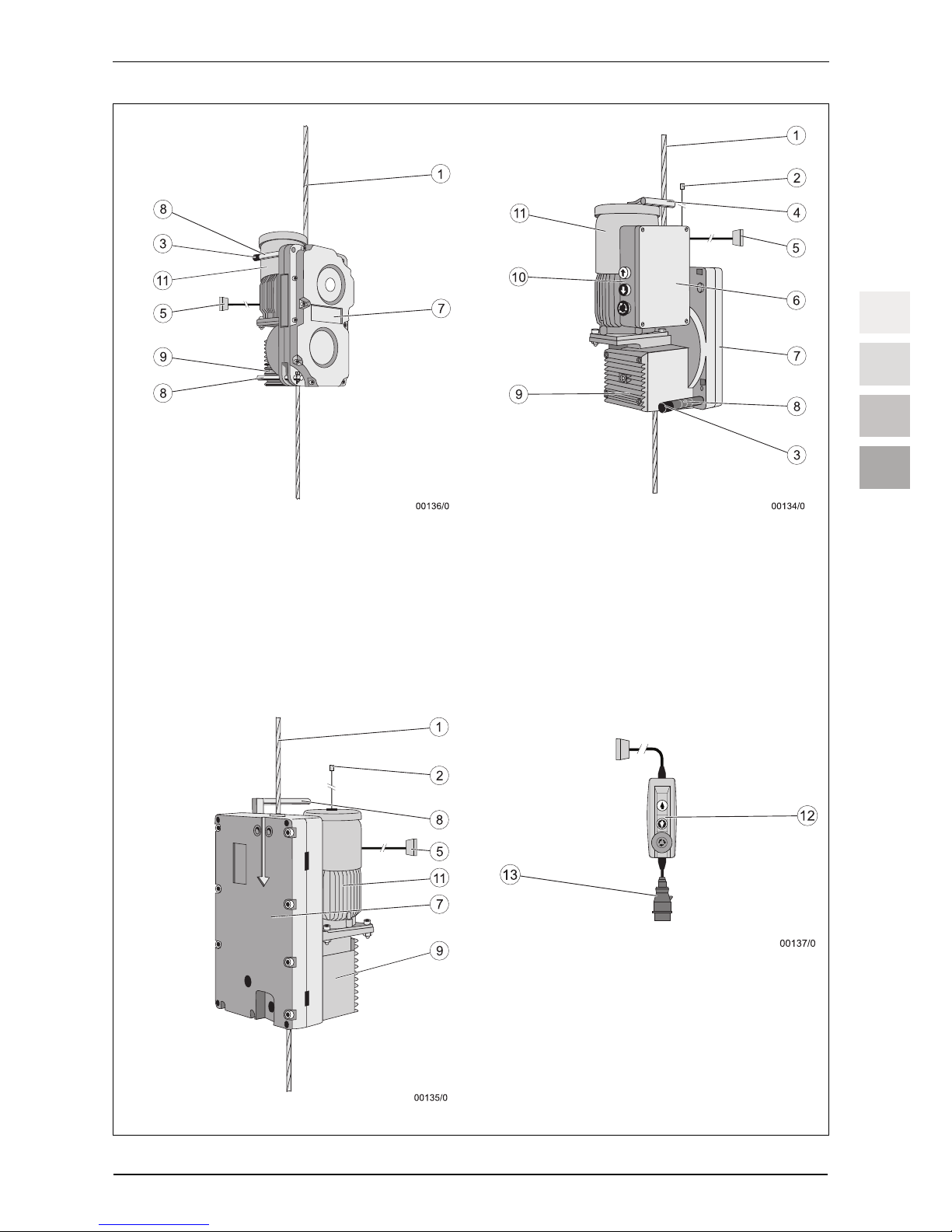
tirakTM
rope
Hoist
Load-carrying
capacity4)
Wire rope speed6)
Connection
Power
Nominal
current
Diameter
Minimum
breaking load5)
Weight
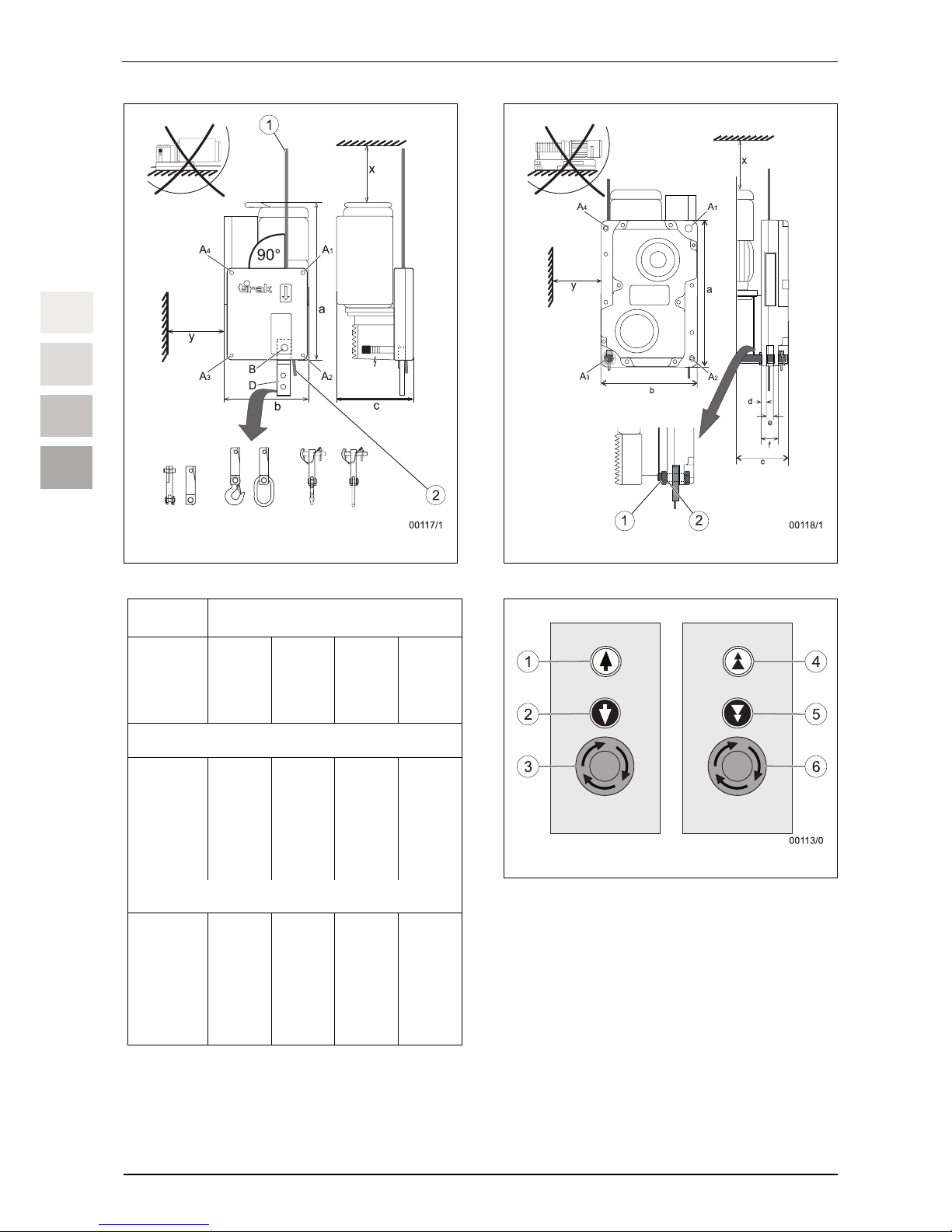
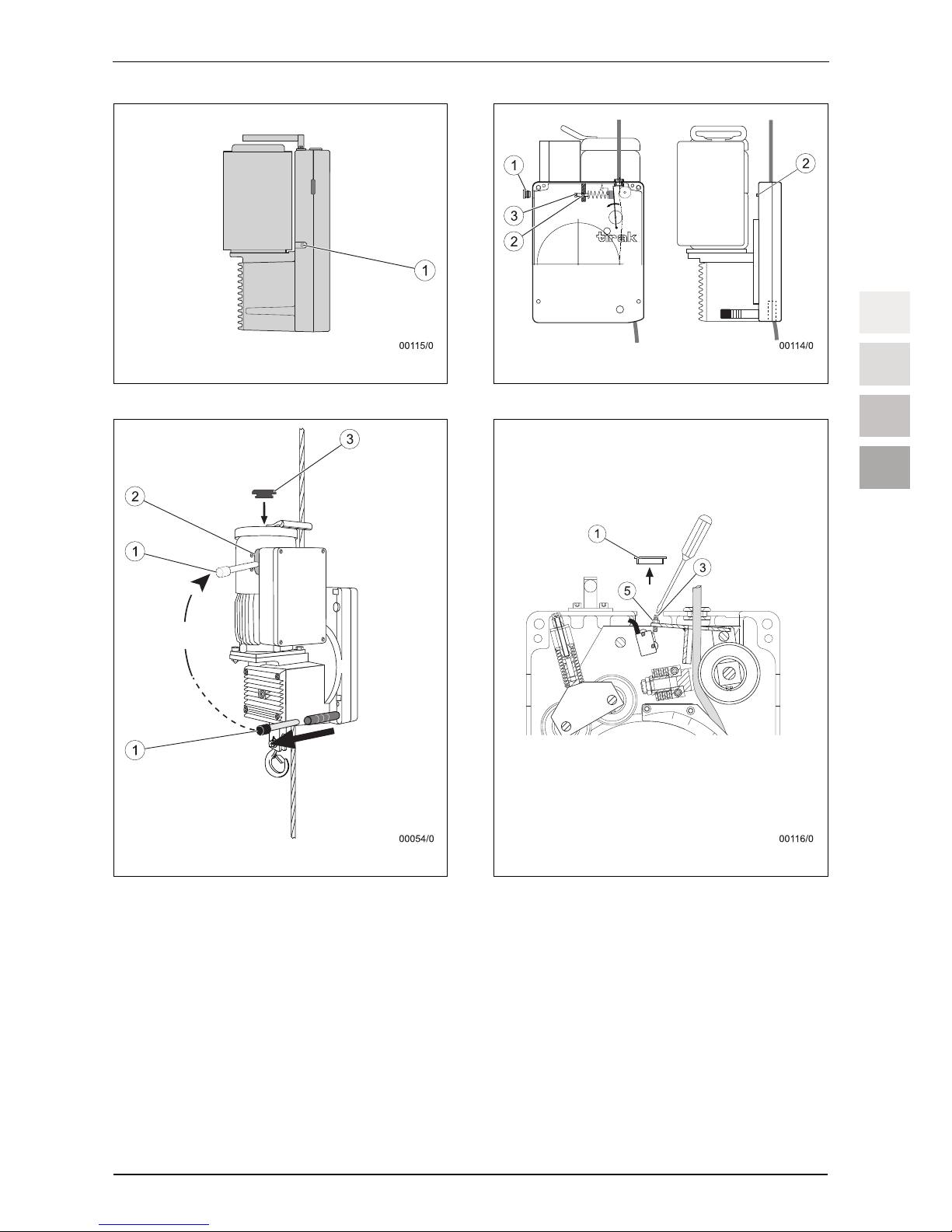
Dimensions / unit size
(see Fig. 2 and 3)
Temperature
range3)
Noise2)
tirakTM
Seil
Winde
Tragfähigkeit4)
Seilgeschwind-
igkeit6)
Anschluss
Leistung
Nennstrom
Durchmesser
Mindest-
bruchkraft5)
Gewicht
Abmessungen /
Einbaumaße
(siehe Abb. 2 und 3)
Temperatur-
bereich3)
Geräuschent-
wicklung2)
tirakTM
câble
Treuil
Capacité de
charge4)
Vitesse du câble6)
Branchement
Puissance
Courant
nominal
Diamètre
Effort de rupture
minimal5)
Poids
Dimensions /
Cotes de montage
(cf. Fig. 2 et 3)
Plage de tempé-
rature3)
Emission so-
nore2)
tirakTM
kabel
Lier
Draagvermogen4)
Kabelsnelheid6)
Aansluiting
Vermogen
Nominale stroom
Diameter
Min. breukkracht5)
Gewicht
Afmetingen/inbouwmaten
(zie Afb. 2 en 3)
Temperatuurbereik3)
Geluidsont-
wikkeling2)
Table/Tabelle/Tableau/Tabel 1
4) X-model series from 1000 kg load carrying capacity: with mechanical load limiting device; X-model series from
1000 kg load carrying capacity: mechanical or electric load limiting device can be supplied as an option. T
Model series: electric load limiting device can be supplied as an option.
X-Typenreihe ab 1000 kg Tragfähigkeit: mit mechanischer Hubkraftbegrenzung; X-Typenreihe bis 1000 kg
Tragfähigkeit: mechanische oder elektronische Hubkraftbegrenzung optional lieferbar. T-Typenreihen:
elektronische Hubkraftbegrenzung optional lieferbar.
Série X à partir d'une capacité de charge de 1000 kg : avec limitation mécanique de la force de levage; série X
jusqu'à une capacité de charge de 1000 kg : limitation mécanique ou électronique de la force de levage dispo-
nible en option. Séries T : limitation électronique de la force de levage disponible en option.
X-type serie vanaf 1000 kg draagvermogen: met mechanische hefkrachtbegrenzing; X-type serie tot 1000 kg
draagvermogen: mechanische of elektronische hefkrachtbegrenzing optioneel leverbaar. T-type series:
elektronische hefkrachtbegrenzing optioneel leverbaar.
1) expanded temperature range on request / erweiterter
Temperaturbereich auf Anfrage / extension de la plage de
température sur demande / uitgebreid temperatuurbereik op
aanvraag
2) at a distance of 1m / in 1 m Abstand / à 1m de distance / op 1 m
afstand
3) Depending on the ambient conditions (ambient temperature,
sunrays, etc.) as well as the possible thermal discharge (dirt, ac-
cumulated heat, etc.)
Abhängig von den Umgebungsbedingungen (Umgebungs-
temperatur, Sonneneinstrahlung, etc.) sowie der möglichen Wär-
meabfuhr (Schmutz, Stauwärme, etc.)
En fonction des conditions ambiantes (température ambiante,
rayonnement solaire etc.) et de l'éventuelle évacuation de la cha-
leur (saleté, accumulation de chaleur etc.)
Afhankelijk van de omgevingsvoorwaarden (omgevings-
temperatuur, zonbestraling, etc.) en van de mogelijke
warmteafleiding (vuil, warmteopstopping, etc.)
a b c x/y
kg m/min
230 V
50 Hz
400 V
50 Hz
kW A
mm
kN
kg mm mm mm mm °C dB
(A)
X 1020 9 – x 1,9 4,6 45 525 297 265
X 1023 9/18 – x 1,9/3,8 4,5/8,5 56 563 307 315
X 1025 4,5/9 – x 0,9/1,9 3,5/4,8 55 563 307 285
X 1020
X 1026
980
4,5/18 – x 0,9/3,8 4/9,6
9
48,1
71 605 332 315
∼250 / 250
-15
…
+70
70
X 1530
X 1530 1500 9 – x 2,8 7
10
73,6
49 522 297 285
∼250 / 250
-15
…
+70
70
X 3050 6 – x 3,8 9,9 105 669 400 372
X 3052 12 – x 7,5 17 117 681 403 372
X 3050
X 3053
3000
6/12 – x 3,8/7,5 9,9/19
14
147,2
156 786 428 442
∼250 / 250
-15
…
+70
78,5